| Table of Contents |
|---|
Overview
The power supply takes 9V as input and uses a power regulator to drop the voltage down to 5V. You can use this kit to portably power your client and projects, like a joystick or remote control car.
A 5V Power Supply that can be used to power the Q-Client Builder Base or Breadboard wirelessly.
|
|
|
|
Things used in this project
Hardware components
Picture | Name | Quantity | Price(As of 7/14/20) | Link |
|---|---|---|---|---|

| Radial LED (5mm) | 1 | $.05/LED (when purchased in a 100 pack)
| Included in Starter Kit Or you can purchase it here |

| Sliding Switch | 1 | ~$.26/Switch | Can be purchased here |

| 1000Ω Resistor | 1 | $.02/Resistor | Included in Starter Kit Or you can purchase it here |
| 220Ω Resistor | 1 | $.02/Resistor | Included in Starter Kit Or you can purchase it here |
| 330Ω Resistor | 1 | $.02/Resistor | Can be purchased here |

| 1uf Capacitor | 1 | ~$.03/Capacitor | Can be purchased here |
 | 100uf Polarized Capacitor | 1 | ~$.03/Capacitor | Can be purchased here |
| 10uf Polarized Capacitor | 1 | ~$.03/Capacitor | Can be purchased here |

| 1N4000 Diode | 2 | ~$.24/Diode | Can be purchased here |

| LM317MB | 1 | ~$.64/Regulator | Can be purchased here |
 | Q-Client Builder Base | 1 | $49 |
Tools Used
Picture | Name | Quantity | Price | Link |
|---|---|---|---|---|
 | Small flat-head screwdriver | 1 | ~$8.74 | Included in Starter Kit Or you can purchase it herepick from one on our Recommend Tools List |
Build Process
The idea
When building a lot of wireless projects you almost always have the need for a good power supply that can be used in different scenarios. This is why we built this 5V Power Supply Prototype.
Video

Build Process
Step 1: Gather and Assemble the Hardware Components
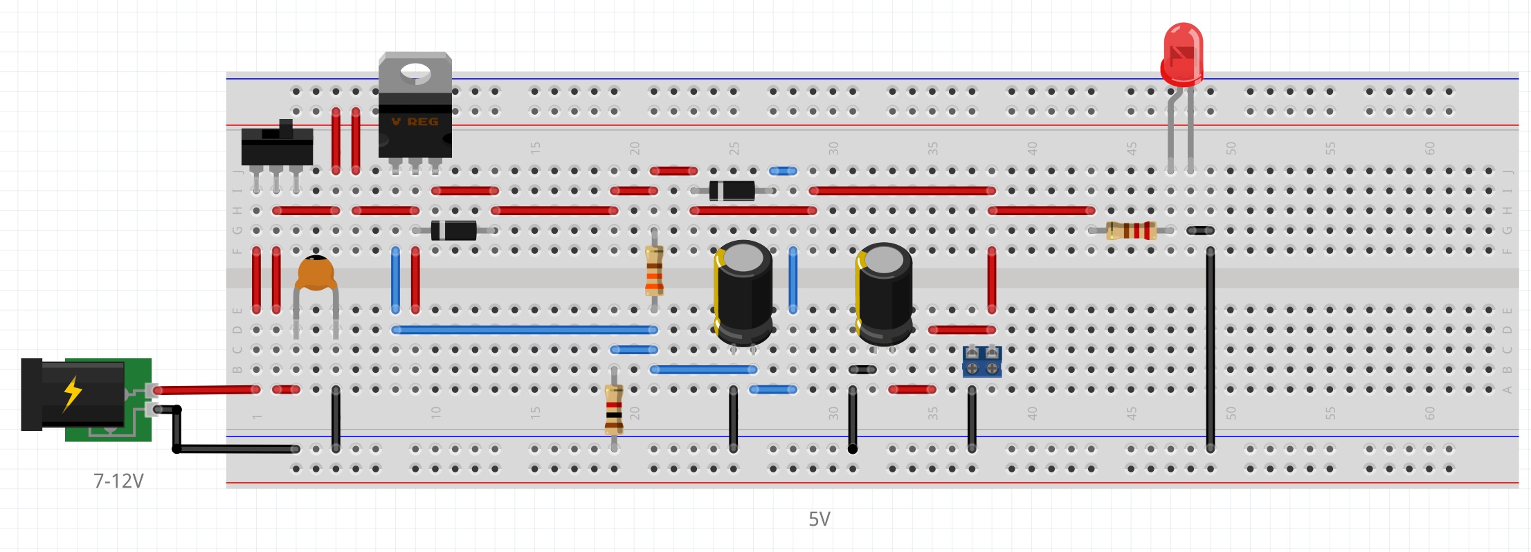
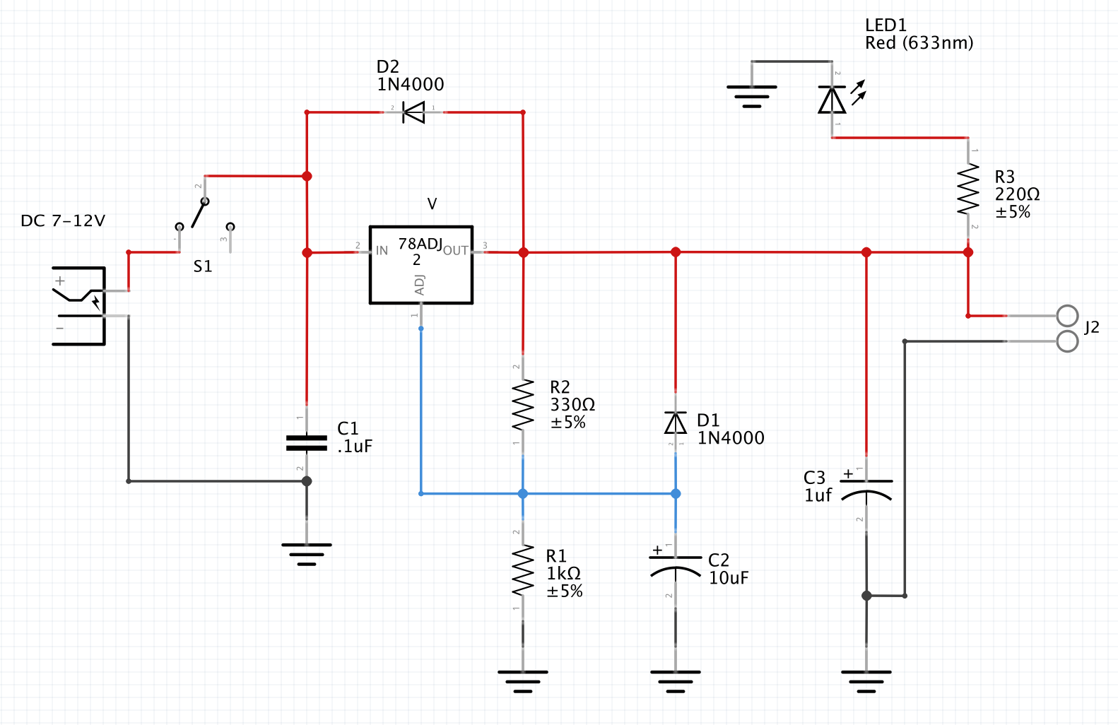
Gather all parts listed above in the parts list and assemble them according to the following schematic:

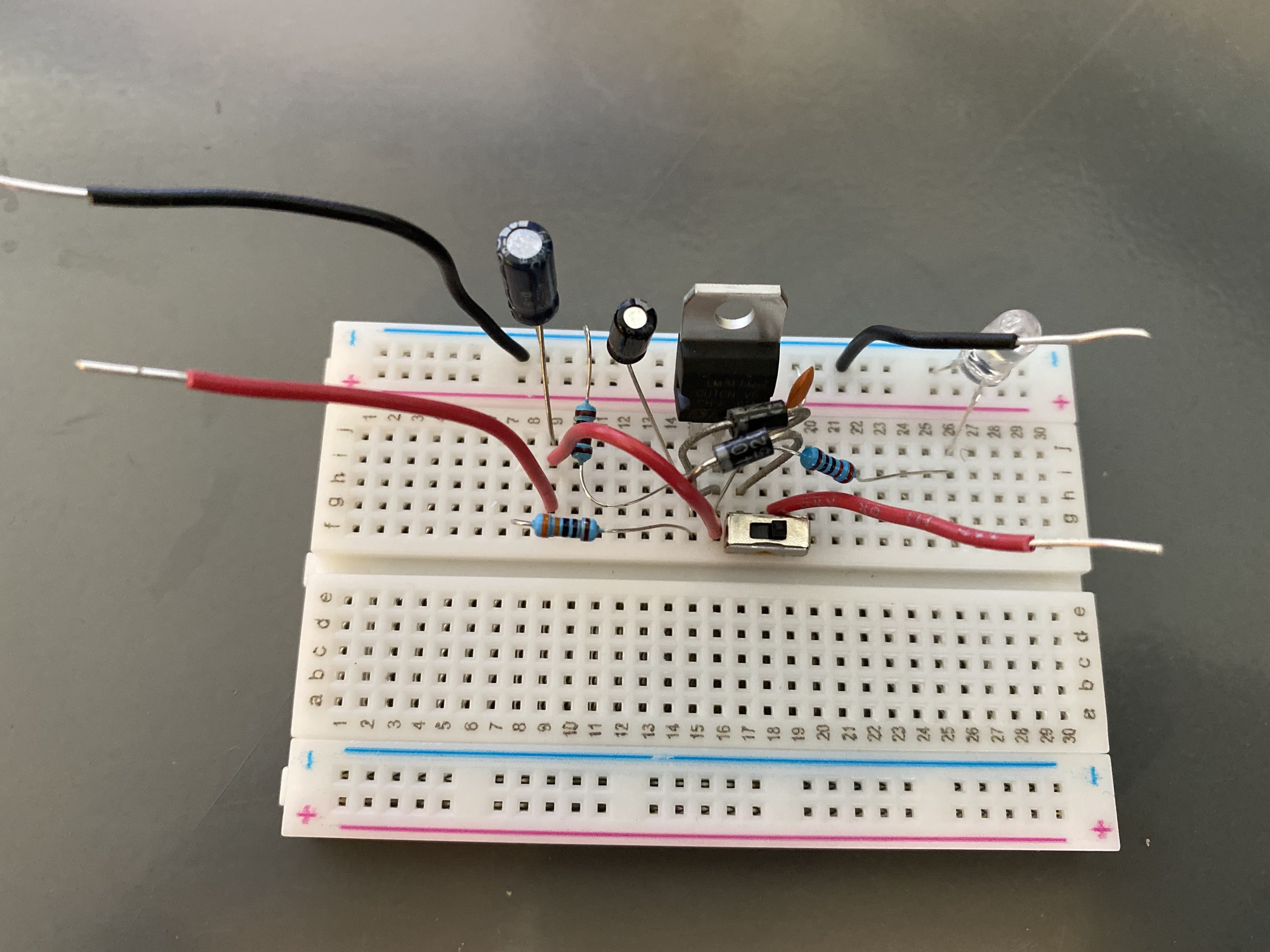
With our prototype build, we did not include a terminal block as it is not entirely necessary, however it does make connecting to the Builder Base to the power supply a bit simpler. In the photo below the input leads are on the right side, and the output leads are on the left.

Step 2: Using the Power Supply with the Builder Base
Once you have your circuit assembled correctly, you can now use it to power the builder base and other projects. To do this, take the Vcc and GND output leads from your power supply and connect them to the 5V and GND ports on your client respectively. You can now attach your 9V battery or other source of power to the input leads.
Once you flip the switch to the on position the LED in the circuit and the LED on your client should illuminate. If this occurs it means you have wired your circuit correctly.
Fritzing & Schematic
Gallery
Resources
Fritzing |
| ||||
|---|---|---|---|---|---|
Schematic | |