| Table of Contents |
|---|
Overview
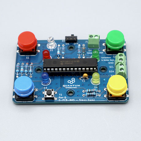
This is the Quantum version of the classic Simon Says game. It is an intermediate project in relation to hardware. The projects this PCB kit can be used for are the Simon Says Game and the Whack-a-mole game.
This DIY Kit page is currently optimized for revision G.
|
|
Required hardware
Components
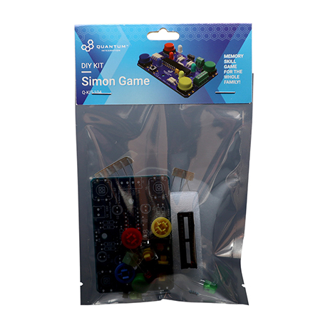
The full DIY Kit can be purchased here
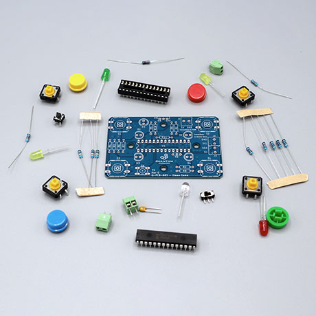
The components are part of the DIY Kit or can be sourced separately with help of the BOM:
| View file | ||
|---|---|---|
|
Picture | Name | Designator | Quantity |
|---|---|---|---|
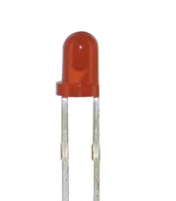 | Red Radial LED (5mm) | D1 | 1 |
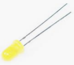 | Yellow Radial LED (5mm) | D4 | 1 |
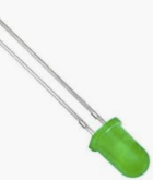 | Green Radial LED (5mm) | D2 | 1 |
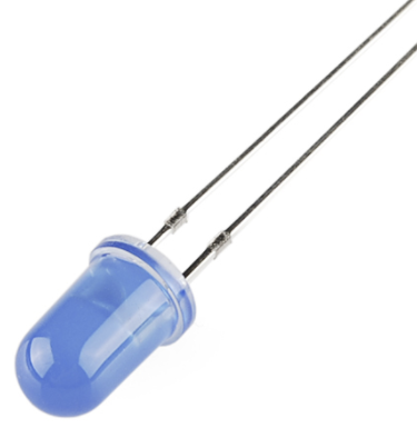 | Blue Radial LED (5mm) | D3 | 1 |
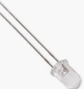 | White Radial LED (5mm) | D5 | 1 |
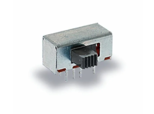
| Sliding Switch | S5 | 1 |
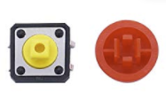 | Tactile button (12x12mm) with color cap (Red) | S1 | 1 |
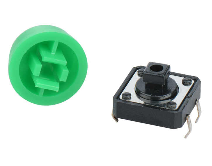 | Tactile button (12x12mm) with color cap (Green) | S2 | 1 |
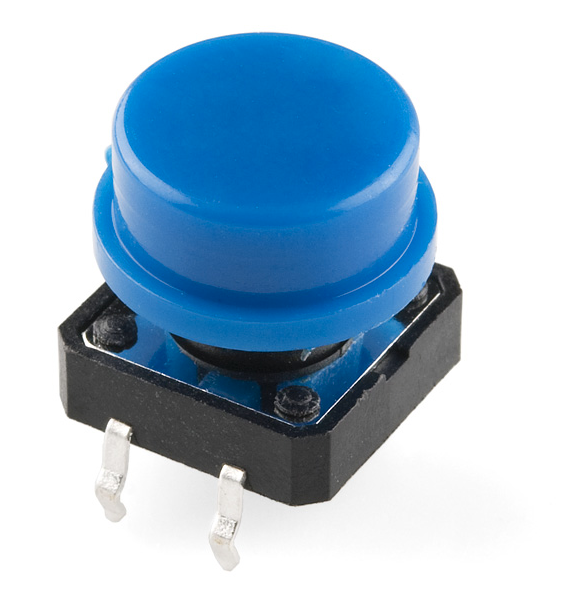 | Tactile button (12x12mm) with color cap (Blue) | S3 | 1 |
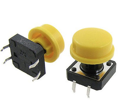 | Tactile button (12x12mm) with color cap (Yellow) | S4 | 1 |
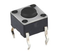 | Tactile Push Button | S6 | 1 |
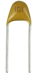 Reads: “104” | 100nf Capacitor | C1 | 1 |
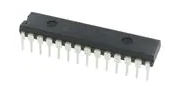 | MCP23017 Port Expander | U1 | 1 |
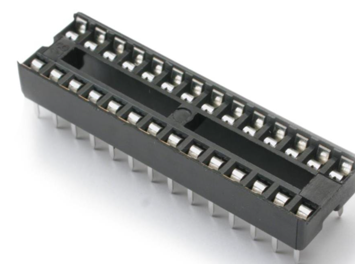 | 28 pin carrier | 1 | |
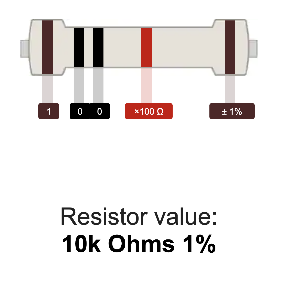 | 10kΩ Resistor | R4, R6, R8, R9, R10 | 5 |
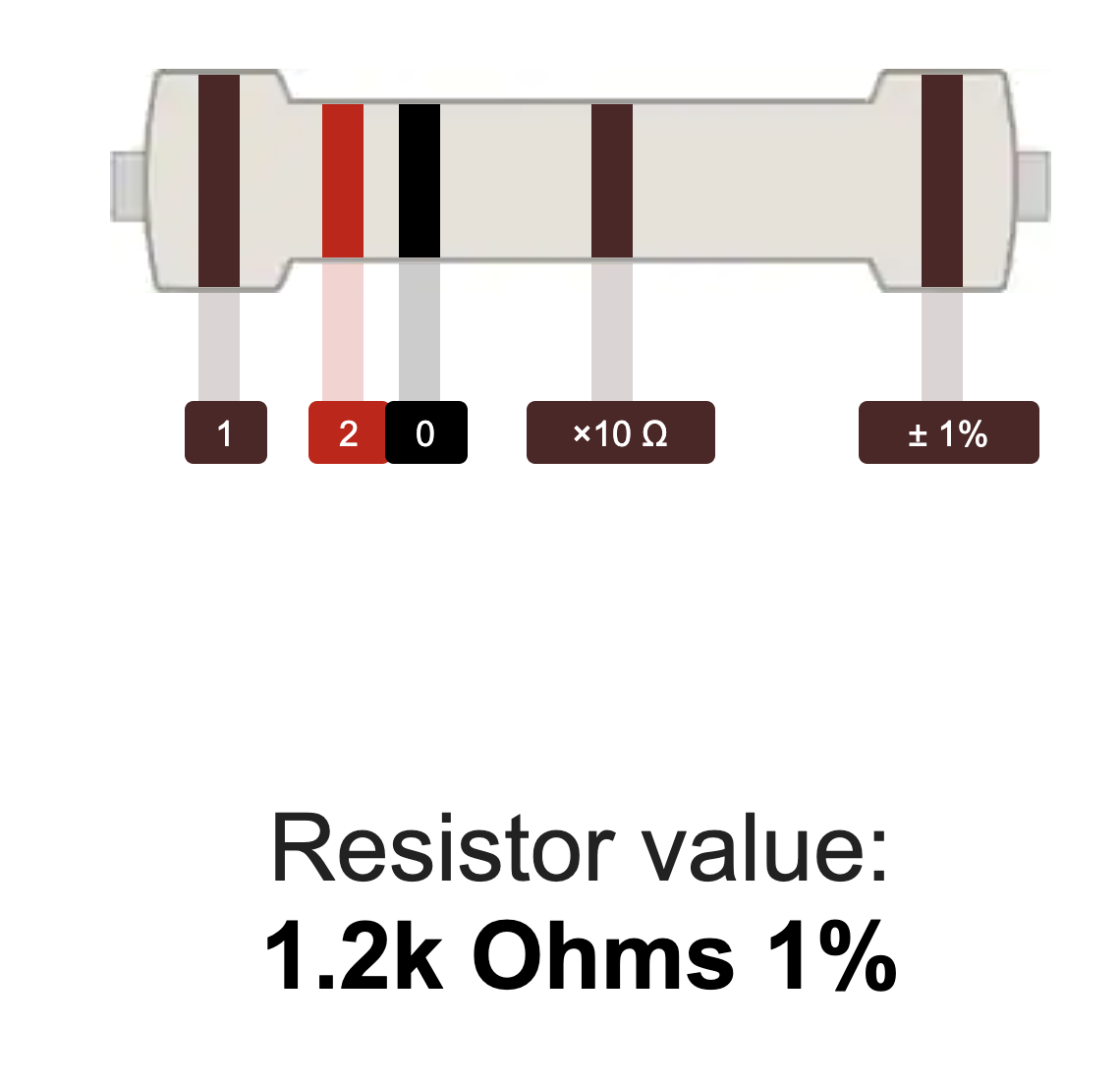 | 1.2kΩ Resistor | R2 | 1 |
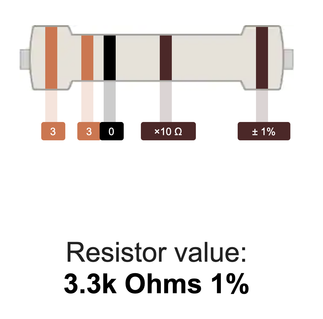 | 3.3kΩ Resistor | R1 | 1 |
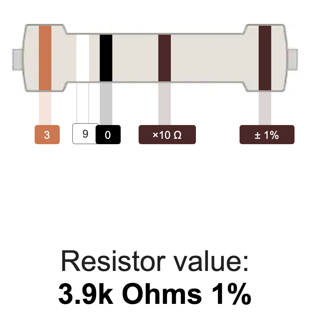 | 3.9kΩ Resistor | R3, R5, R11 | 3 |
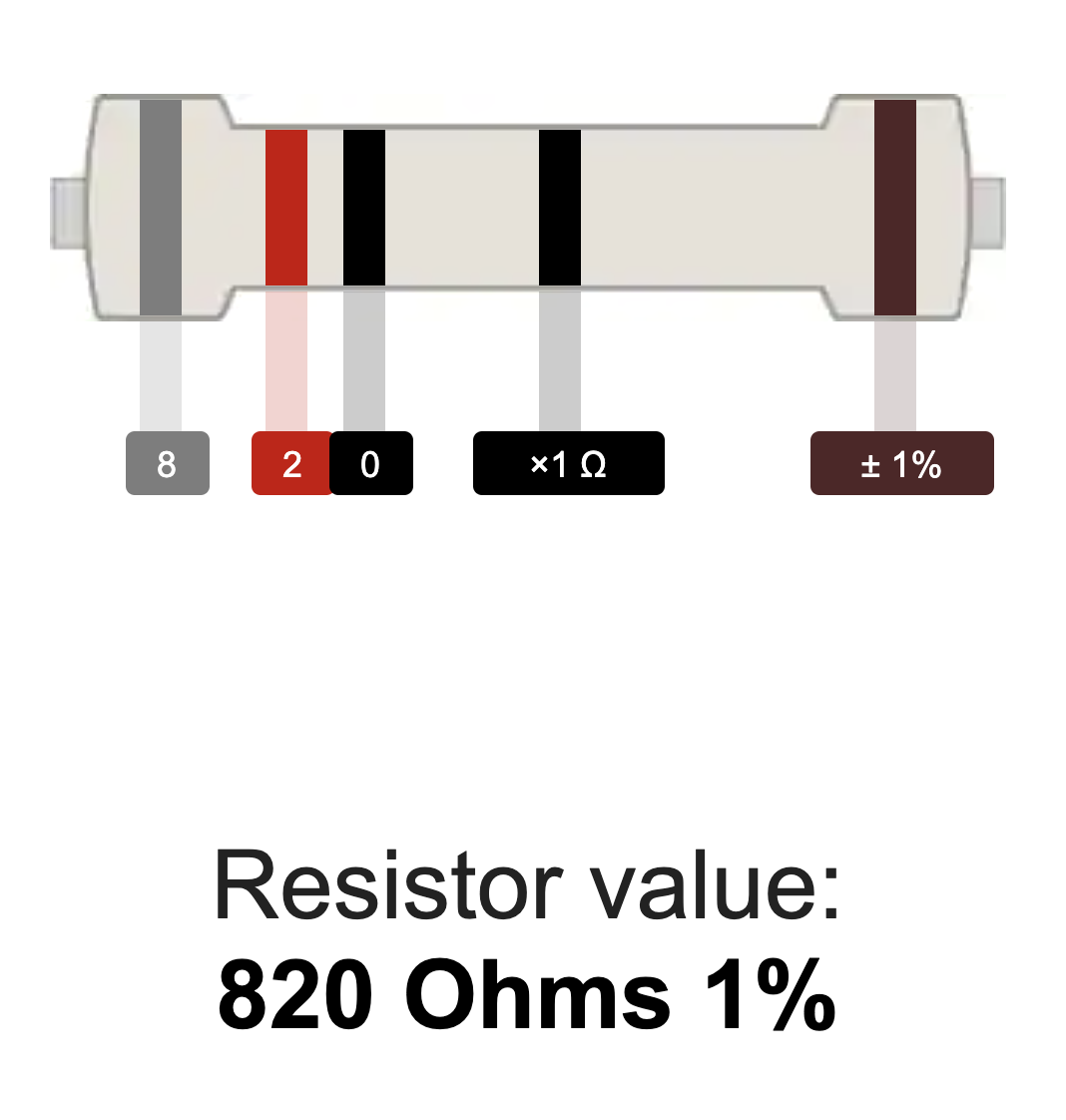 | 820Ω Resistor | R7 | 1 |
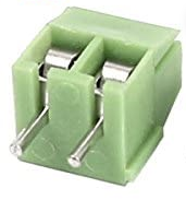 | 1x2 3.5mm Terminal Block | J1, J2, J3 | 3 |
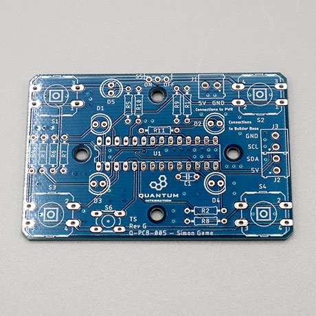
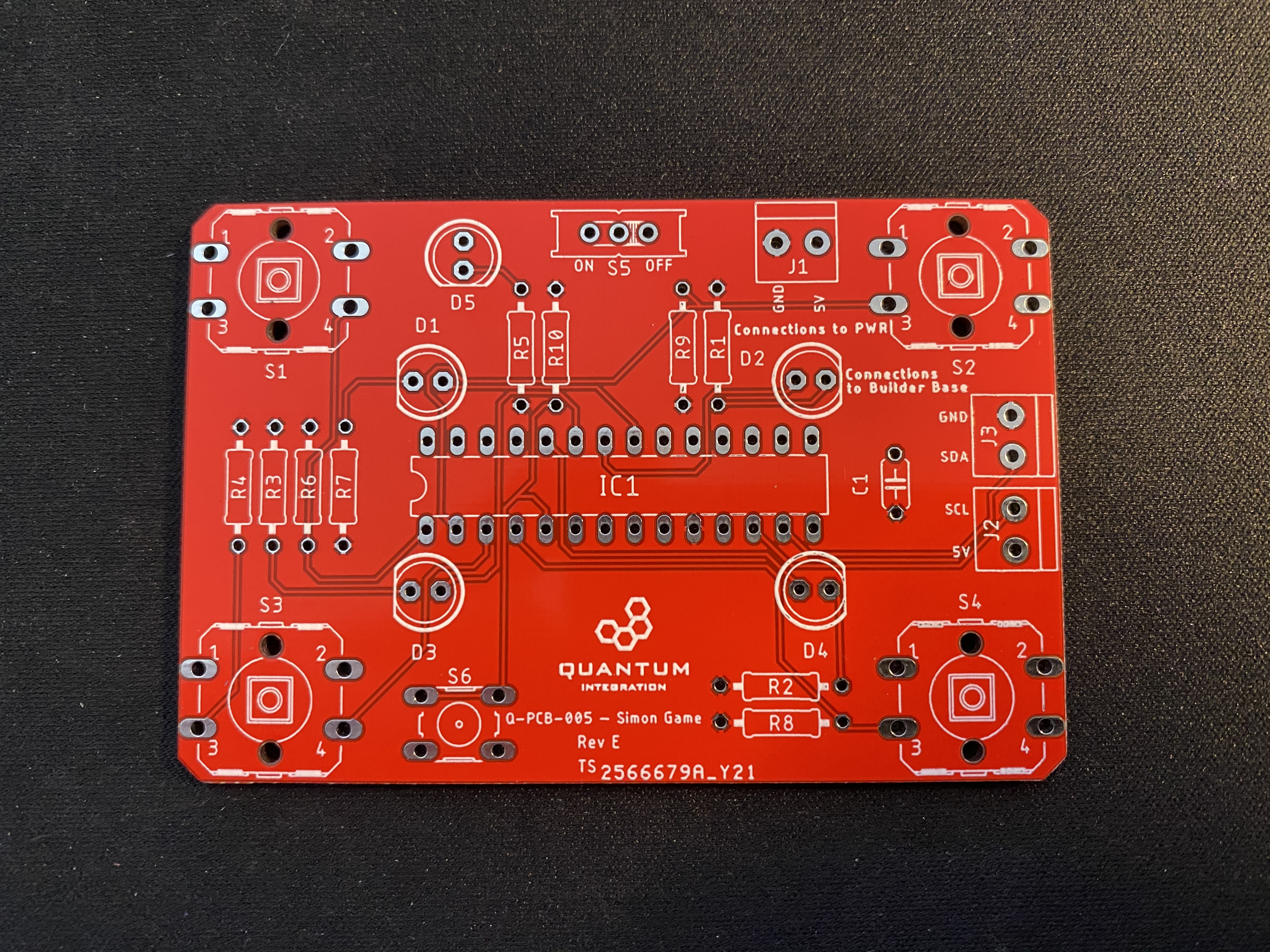 | Simon Says PCB | Q-PCB-005 | 1 |
Tools Used
Picture | Name | Quantity | Link |
|---|---|---|---|
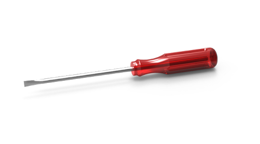 | Small flat-head screwdriver | 1 | Included in Starter Kit or you can pick from one on our Recommended Tools List |
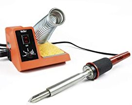 | Soldering Iron | 1 | You can pick from one on our Recommended Tools List |
 | Solder | 1 | You can pick from one on our Recommended Tools List |
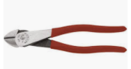 | Diagonal Cutters | 1 | You can pick from one on our Recommended Tools List |
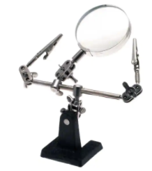 | Work Holder | 1 | You can pick from one on our Recommended Tools List |
Story
The Idea
We intended to reproduce a game that was fun to play and was highly educational to build. In this DIY Kit we explore how to use an MCP23017 port expander and to talk to multiple IO pins via a two wire bus.
The Video
| Widget Connector | ||||||||||
|---|---|---|---|---|---|---|---|---|---|---|
|
Build Process
Step 1: PCB Assembly and Soldering
Take a look at the required components above and determine their final position on the PCB. The following images should be a good reference:
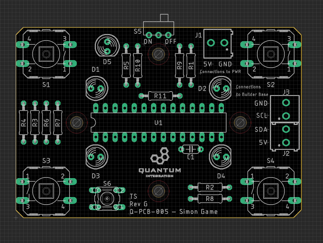
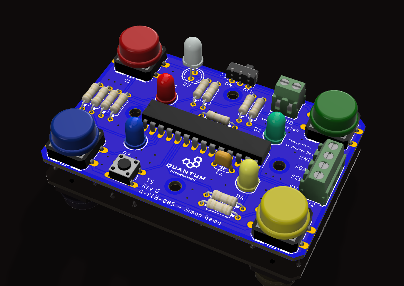
Place groups of components on the board and then solder them to the pads. It is recommended to start with components with the lowest profile, like for example resistor and them move up to components like buttons with higher profile.
To determine the values of the given resistors and to place them in the correct position, please refer to a resistor color code calculator like this one:
Using some form of work holder is advised. You can find a list of suitable work holders on our Recommended Tools List.
To help you placing the big chip for the IO expansion, we put a 28-pin carrier into the kit. This one can be soldered down and the chip can simply be plugged in on top of the carrier.
Step 2: Connecting to the Builder Base
To connect the IDY Kit to the Builder Base you will need four male to male jumper wires and your flathead screwdriver.
Please connect the Builder Base to connectors J2 and J3 of the DIY Kit. The labeling of the connectors is the same as on the Builder Base. The Builder Base can now get powered via USB and power the Kit as well, or get powered through the Kit. For that, J1 of the Kit has to be powered with 5V. A switch can interrupt the power in this configuration to save energy if for example a battery is used.
Projects
Simon Says
The project page can be found here Simon Game Project .
In this section we will explain how to make the DIY Kit compatible with the project.
First of all, we need to connect the PCB to the Builder Base. For that we simply connect the Builder Base to connectors J2 and J3 of the DIY Kit. The labeling of the connectors is the same as on the Builder Base. The Builder Base can now get powered via USB and power the Kit as well, or get powered through the Kit. For that, J1 of the Kit has to be powered with 5V. A switch can interrupt the power in this configuration to save energy if for example a battery is used.
Firmware and app are mostly the same! Please refer to the instructions in this section.
Just one difference occurs, the blue and green buttons are swapped in the firmware regarding the pins they connect to on the MCP23017. The complete table of button connections is referenced below:
Button | Driver | I2C Address | Channel | Pull up |
|---|---|---|---|---|
Red | MCP23017/8 | 0x27 | B0 | Disabled |
Green | MCP23017/8 | 0x27 | B1 | Disabled |
Blue | MCP23017/8 | 0x27 | B2 | Disabled |
Yellow | MCP23017/8 | 0x27 | B3 | Disabled |
Reset | MCP23017/8 | 0x27 | B4 | Disabled |
The correct firmware can be found here:
| View file | ||
|---|---|---|
|
Whack-A-Mole
The project page can be found here Whack a mole Project.
The whack-a-mole project uses the DIY Kit as one of its components! Head over to the project page to check it out.
Gallery
Resources
Current revision
Assembly files for the current revision of the DIY Kit (Rev G): | https://github.com/QuantumIntegration/Q-PCB-005-Simon-Game-Hardware-Files/tree/Rev_G |
|---|
Older revisions
- | - |
|---|