| Table of Contents |
|---|
Introduction
This Rotary Encoder driver can be used in conjunction with an incremental hardware rotary encoder. A rotary encoder, also called a shaft encoder, is an electro-mechanical device that converts the angular position or motion of a shaft or axle to analog or digital output signals.
Driver Parameters
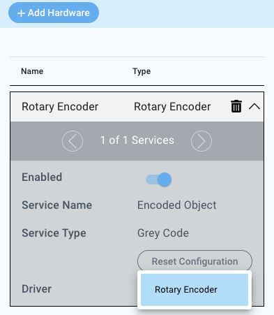
The Rotary Encoder has three parameters that need to be configured:
CLK Pin
This pin provides the clock line from the rotary encoder. Any pin is suitable.
DT Pin
This pin provides the data line from the rotary encoder. The signal occurs either before or after the clock signal determining the direction the rotary encoder is turned. Any pin is suitable.
BTN Pin
This is the pin that transfers the signal when the rotary encoder is pushed on top. Any pin is suitable.
Wiring
Example
The GP0, GP1 and GP2 pins of the Builder Base are connected to the Clock, Data and Switch pin of the rotary encoder. The GND and V+ pins of the rotary encoder are then connected to the GND and 3.3V ports on the Builder Base respectively.
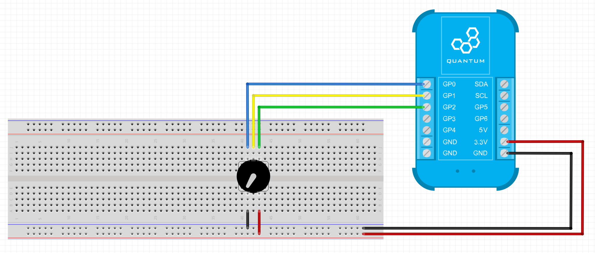
Breadboard
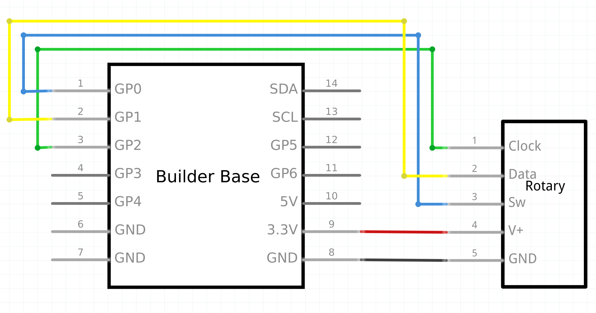
Schematic
Used Pins
Used Pins | Description |
|---|---|
GP0 (Can be any GP pin) | The clock line |
GP1 (Can be any GP pin) | The data line |
GP2 (Can be any GP pin) | The switch line |
3.3V | This pin provides the power |
GND | This pin provides the GND |
How to write an App
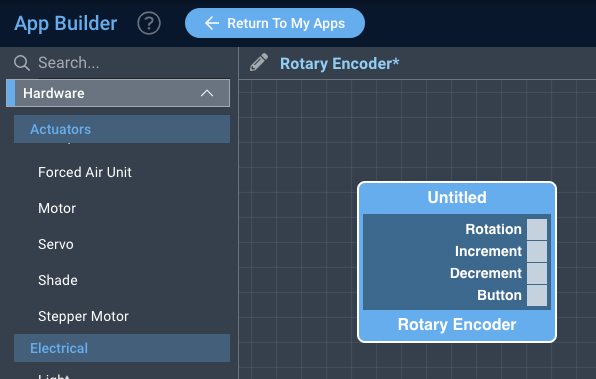
Navigate to the App Builder and create a new application. You can find the “Light” code object under the “Hardware” Tab in the object drop down menu on the left, or you can also use the search bar.
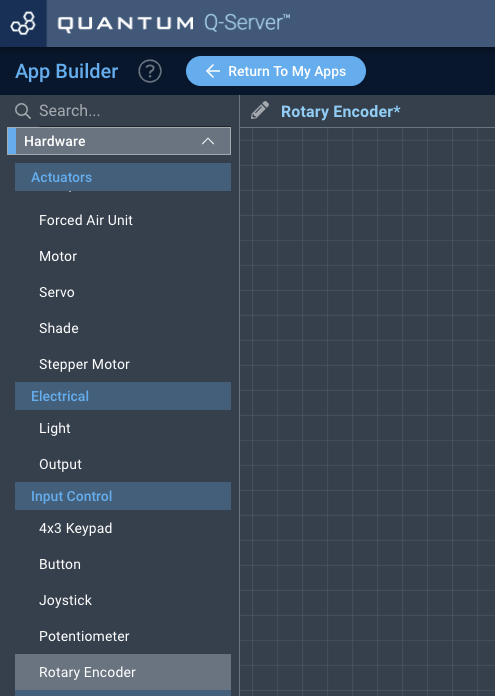
Drag the “Rotary Encoder” object onto the canvas.
Next, locate the debug and the
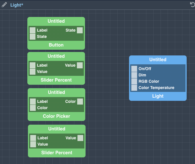
Finally, connect the button object to the on/off port, the slider percent object to the dim port, the color picker to the RGB color port, and the other slider percent object to the color temperature port.

How to create a firmware
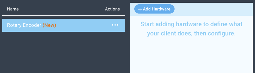
Navigate to the Firmware Builder and create a new firmware file.
Click the “+ Add Hardware” button which will open a modal window. Scroll down in the list to find the “Electrical” section and select the “Light” hardware option.
Give your device a name, and click “Add Hardware”
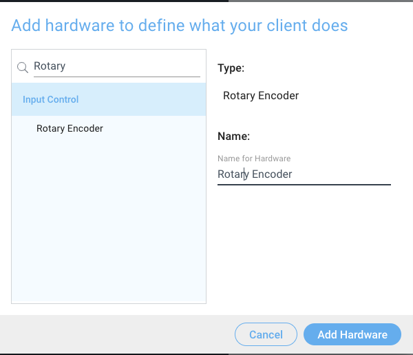
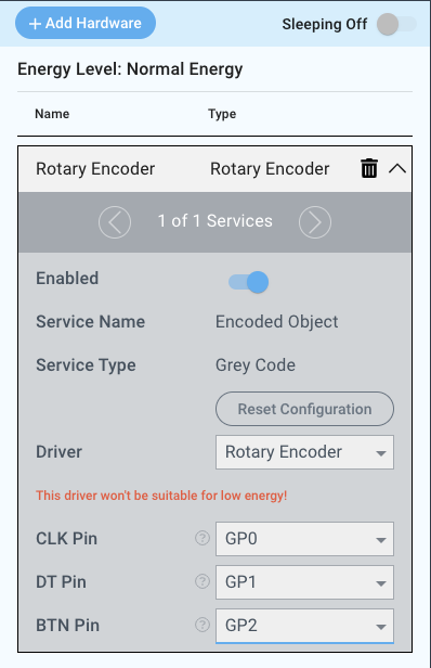
Next, select the “Rotary Encoder” driver under the driver dropdown menu.

For this example we select:
CLK Pin: GP0
DT Pin: GP1
BTN Pin: GP2
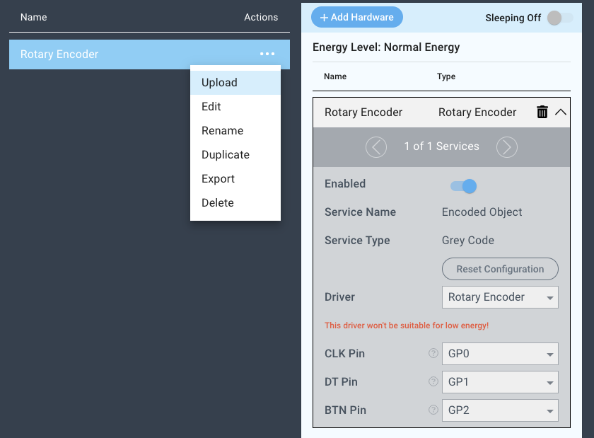
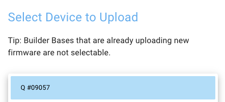
You may now save your firmware file and upload it to one of your clients.
Supported Hardware
Rotary Encoder
Downloads
Apps
| View file | ||
|---|---|---|
|
Firmware
| View file | ||
|---|---|---|
|
Assets