| Table of Contents |
|---|
Introduction
The GPIO driver for 7-Segment displays is used in conjunction with a generic 7 segment brick. The LEDs of the brick are directly driven by the GPIO pins of the Builder Base.
Driver Parameters
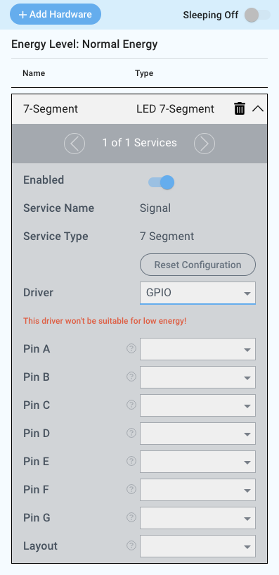
The GPIO driver for 7-Segment displays has eight parameters that need to be configured:
Pin A
The pin connected to the A segment.
Pin B
The pin connected to the B segment.
Pin C
The pin connected to the C segment.
Pin D
The pin connected to the D segment.
Pin E
The pin connected to the E segment.
Pin F
The pin connected to the F segment.
Pin G
The pin connected to the G segment.
Layout
This determines whether the common connection is to GND or 3.3V. Options are common anode (see: https://quantumintegrate.atlassian.net/wiki/spaces/QFR/pages/145752954/Use+the+GPIO+driver+for+7-Segment+displays#Common-Anode ) or common cathode (see: https://quantumintegrate.atlassian.net/wiki/spaces/QFR/pages/145752954/Use+the+GPIO+driver+for+7-Segment+displays#Common-Cathode ).
Wiring
The pinout for generic seven segment bricks can be seen below:
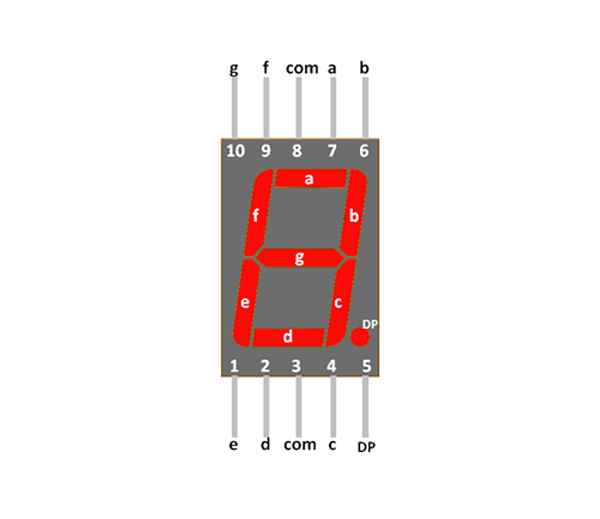
com can be either GND or 3.3V depending on the brick
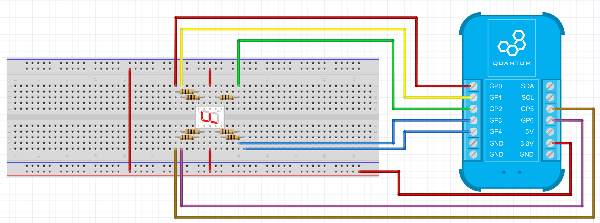
Common Anode
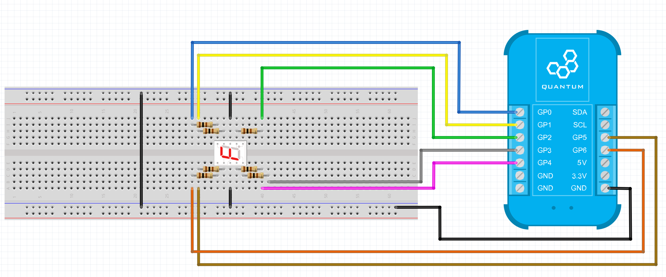
All 7 GPIO pins of the Builder Base are connected to the segments of the Builder Base through current limiting resistors. the common anode of the 7 segment brick is connected to the 3.3V pin.
Breadboard
Schematic
Used Pins
Used Pins | Description |
|---|---|
GP0 (can be any GP pin) | Pin connected to the A segment |
GP1 (can be any GP pin) | Pin connected to the B segment |
GP2 (can be any GP pin) | Pin connected to the C segment |
GP3 (can be any GP pin) | Pin connected to the D segment |
GP4 (can be any GP pin) | Pin connected to the E segment |
GP5 (can be any GP pin) | Pin connected to the G segment |
GP6 (can be any GP pin) | Pin connected to the F segment |
3.3V | This pin provides the common anode 3.3V |
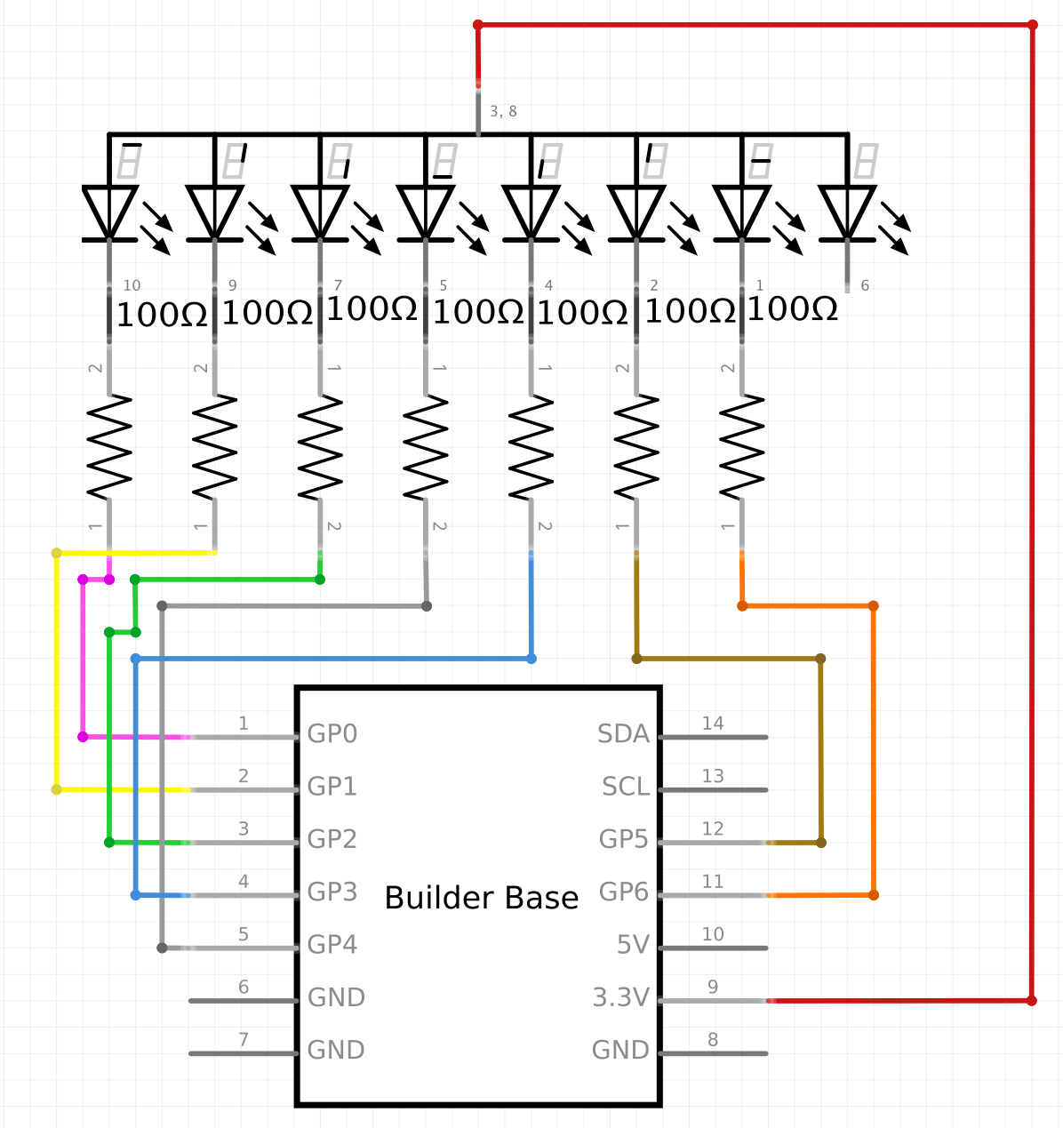
Common Cathode
All 7 GPIO pins of the Builder Base are connected to the segments of the Builder Base through current limiting resistors. The common cathode of the 7 segment brick is connected to the GND pin.
Breadboard
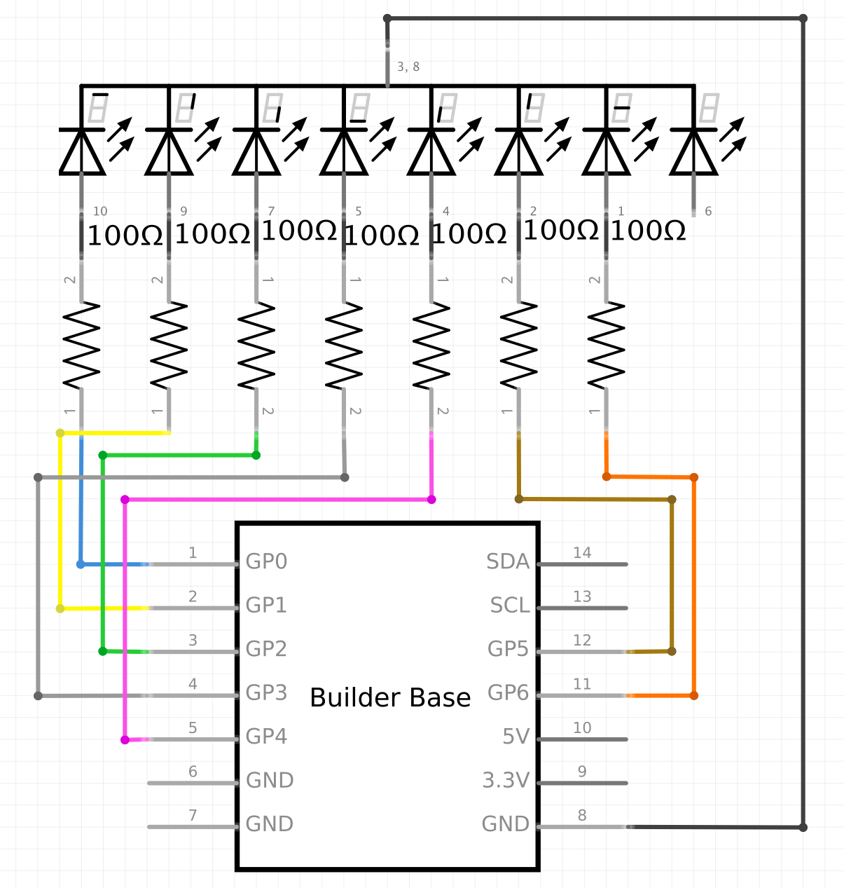
Schematic
Used Pins
Used Pins | Description |
|---|---|
GP0 (can be any GP pin) | Pin connected to the A segment |
GP1 (can be any GP pin) | Pin connected to the B segment |
GP2 (can be any GP pin) | Pin connected to the C segment |
GP3 (can be any GP pin) | Pin connected to the D segment |
GP4 (can be any GP pin) | Pin connected to the E segment |
GP5 (can be any GP pin) | Pin connected to the G segment |
GP6 (can be any GP pin) | Pin connected to the F segment |
GND | This pin provides the common cathode GND |
How to write an App
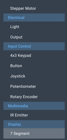
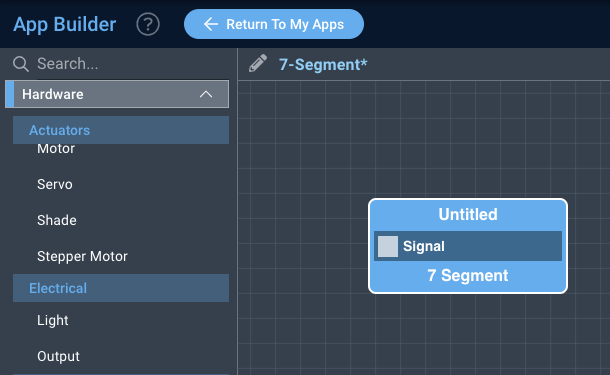
Navigate to the App Builder and create a new application. You can find the “7-Segment” code object under the “Hardware” Tab in the object drop down menu on the left, or you can also use the search bar.
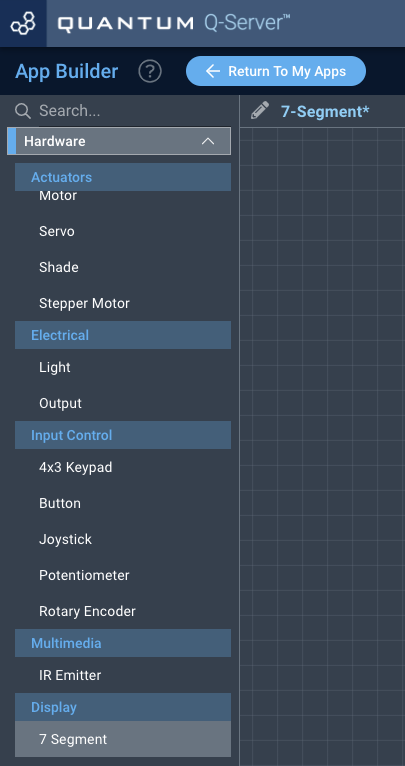
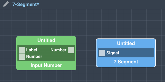
Drag the “7-Segment” object onto the canvas.
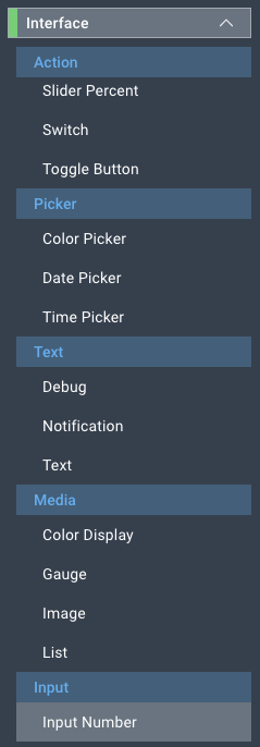
Next, located under the interface tab find the “Input Number” object and drag it onto the canvas.
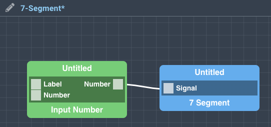
Finally, connect the number port from the “Input Number” object to the “Signal” port on the 7-Segment object, and save your application.
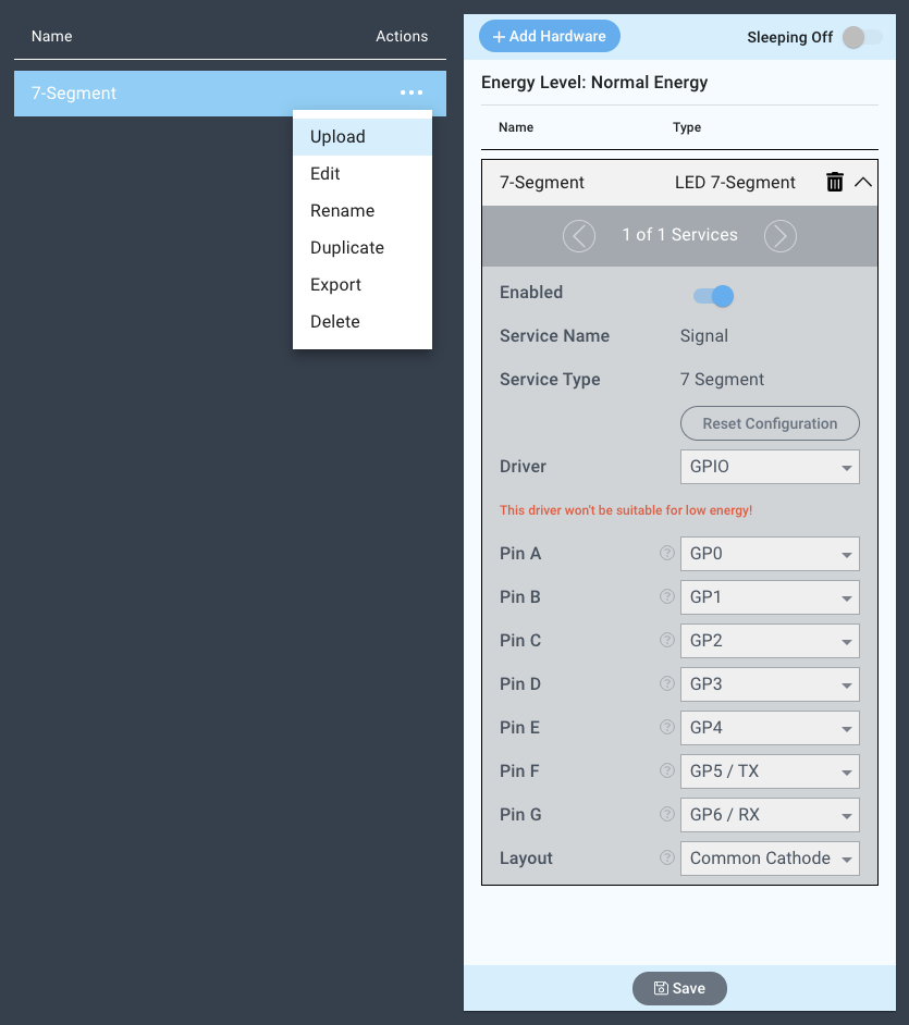
How to create a firmware
Navigate to the Firmware Builder and create a new firmware file.
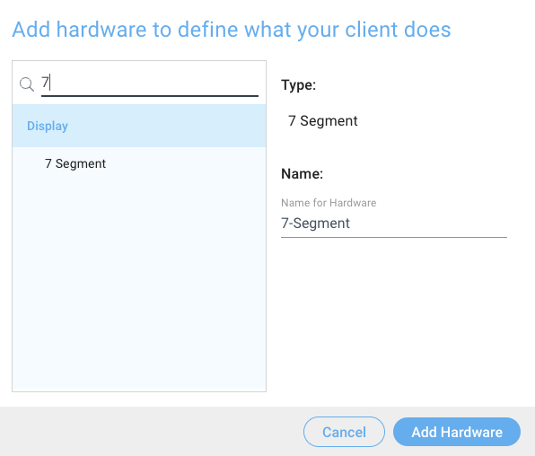
Click the “+ Add Hardware” button which will open a modal window. Scroll down in the list to find the “Display” section and select the “7-Segment” hardware option.
Give your device a name, and click “Add Hardware”

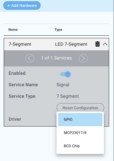
Next, select the “Dimmed” “GPIO” driver under the driver dropdown menu.
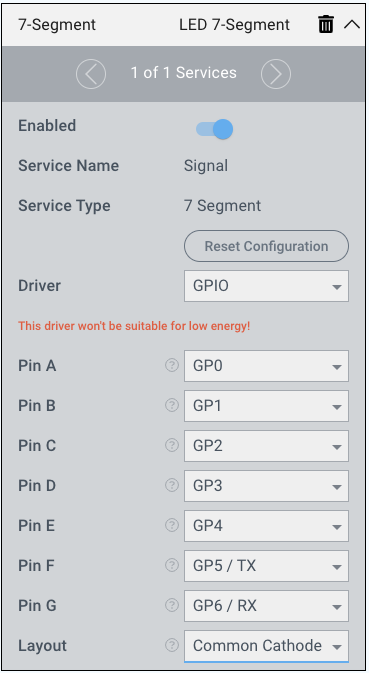
For this example we select:
Pin A: GP0
Pin B: GP1
Pin C: GP2
Pin D: GP3
Pin E: GP4
Pin F: GP5/TX
Pin G: GP6/RX
Layout: Common Cathode
You may now save your firmware file and upload it to one of your clients.
Supported Hardware
7-Segment Displays
Downloads
Apps
| View file | ||
|---|---|---|
|
Firmware
| View file | ||
|---|---|---|
|
Assets