
| Table of Contents |
|---|
Overview
This is the Quantum revision of the classic Simon Says game. It is an intermediate project in relation to hardware, but an advanced project in terms of programming. All firmware and program files needed for this project are available in the resources section below! We intended to reproduce a game that was fun to play and was highly educational to build. In this project we explore how to use an MCP23017 port expander, and build somewhat complex game logic using the Quantum Platform.
You can also build this project with one of our DIY Kits!
Check out the the Simon Game DIY Kit page to find out how.
|
|
|
|


Hardware Components
Picture | Name | Quantity | Link | ||
|---|---|---|---|---|---|
 | Red Radial LED (5mm) | 1 | Included in Component Kit Or you can purchase it here | ||
 | Yellow Radial LED (5mm) | 1 | Can be purchased here | ||
 | Green Radial LED (5mm) | 1 | Included in Component Kit Or you can purchase it here | ||
 | Blue Radial LED (5mm) | 1 | Included in Component Kit Or you can purchase it here | ||
 | White Radial LED (5mm) | 1 | Can be purchased here | ||
 | Tactile button (12x12mm) with color cap (Red)
| 5 | You can purchase here | ||
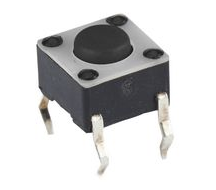 | Tactile Push Button | 5 | Included in Component Kit Or you can purchase it here | ||
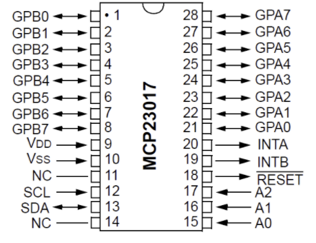
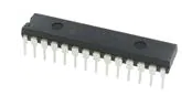 | MCP23017 Port Expander | 1 | Included in Component Kit Or you can purchase it here | ||
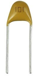 | 100nf Capacitor | 2 | Can be purchased here | ||
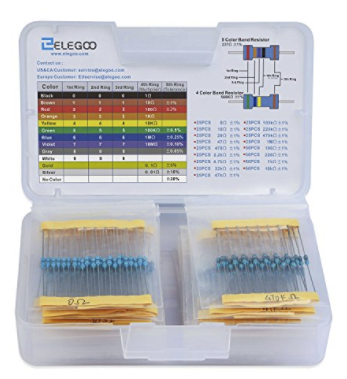 | 10kΩ Resistor | 5 | Included in Component Kit Or you can purchase it here | ||
| 220Ω Resistor | 1 | Included in Component Kit Or you can purchase it here | ||
| 150Ω Resistor | 3 | Can be purchased here | ||
| 120Ω Resistor | 1 | Can be purchased here | ||
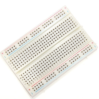 | Breadboard (Large) | 2 | Included in Component Kit Or you can purchase it here | ||
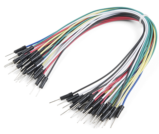 | Jumper Cables (MM) | ~45 | Included in Component Kit Or you can purchase it here | ||
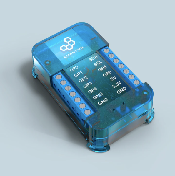 | Q-Client Builder Base | 1 |
Tools Used
Picture | Name | Quantity | Link |
|---|---|---|---|
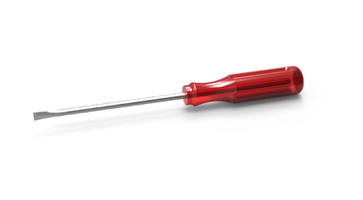
| Small flat-head screwdriver | 1 | Included in Component Kit Or you can pick from one on our Recommended Tools List |
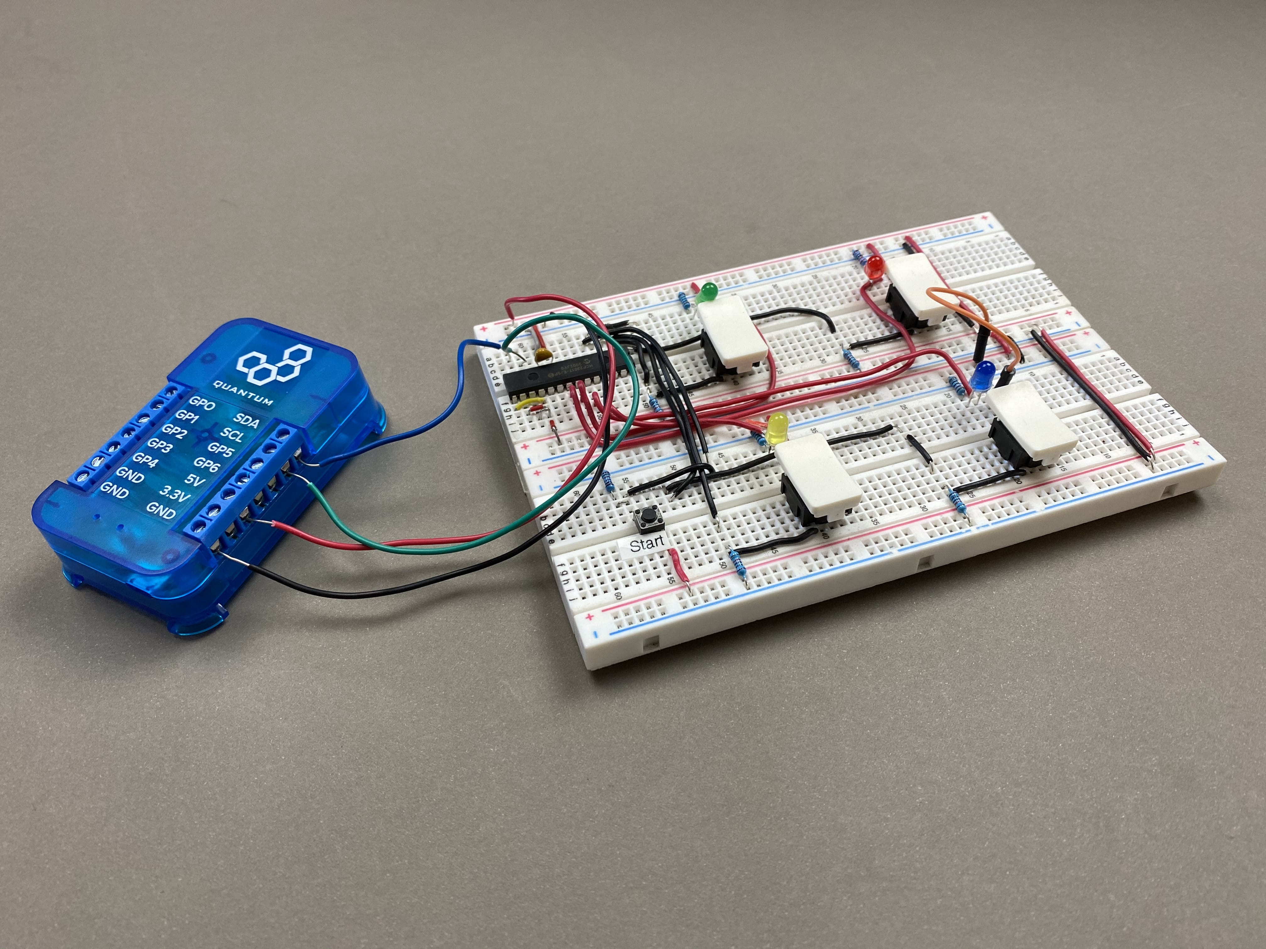
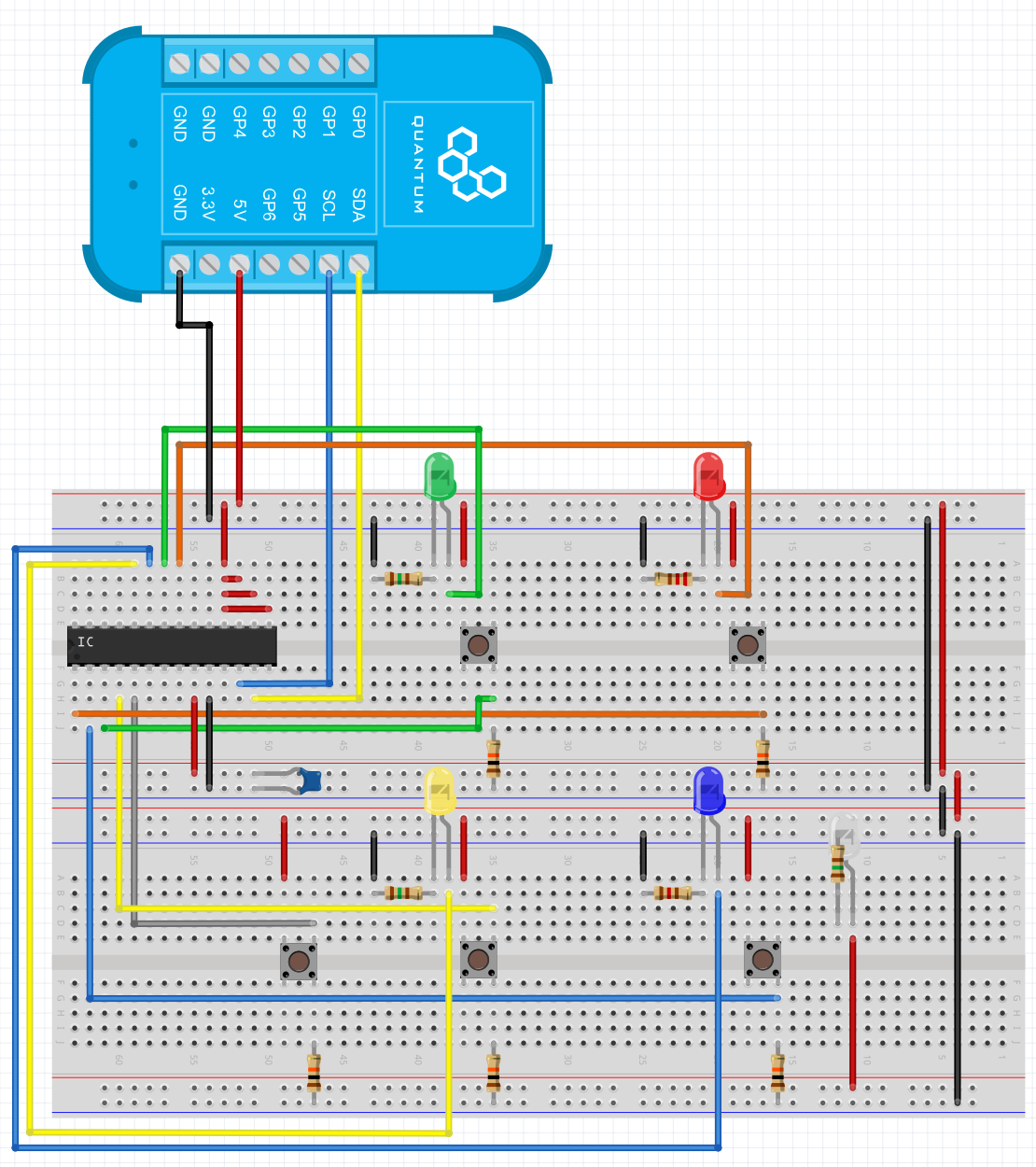
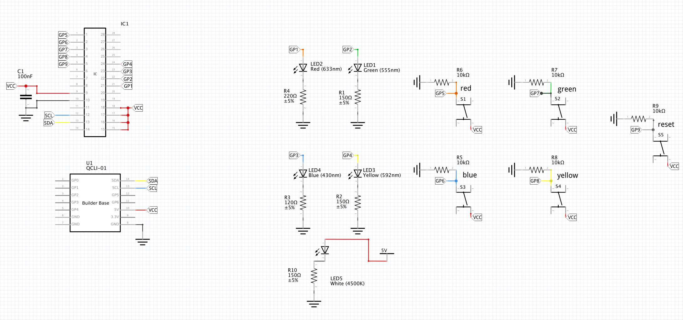
Assemble the Circuit
Gather both the client that you intend to build the Simon Says game with and all of the parts detailed in the parts list above.
We are using an MCP23017 port expander to expand the number of I/O ports on the Builder Base by sixteen, however we will only be using nine of these extra ports.
The port expander connects to the Builder Base through the SCL and SDA ports and communicates via I2C communication.


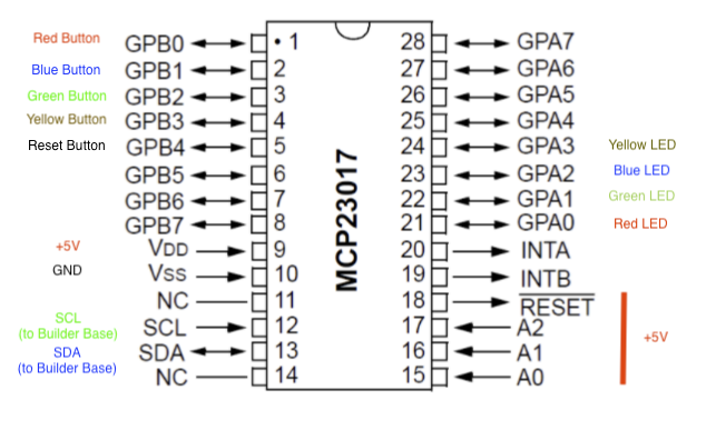
Hardware Component | GPA(x) | GPB(x) |
|---|---|---|
Red Button | - | B0 |
Blue Button | - | B1 |
Green Button | - | B2 |
Yellow Button | - | B3 |
Reset Button | - | B4 |
Red LED | A0 | - |
Green LED | A1 | - |
Blue LED | A2 | - |
Yellow LED | A3 | - |

Pair the Builder Base
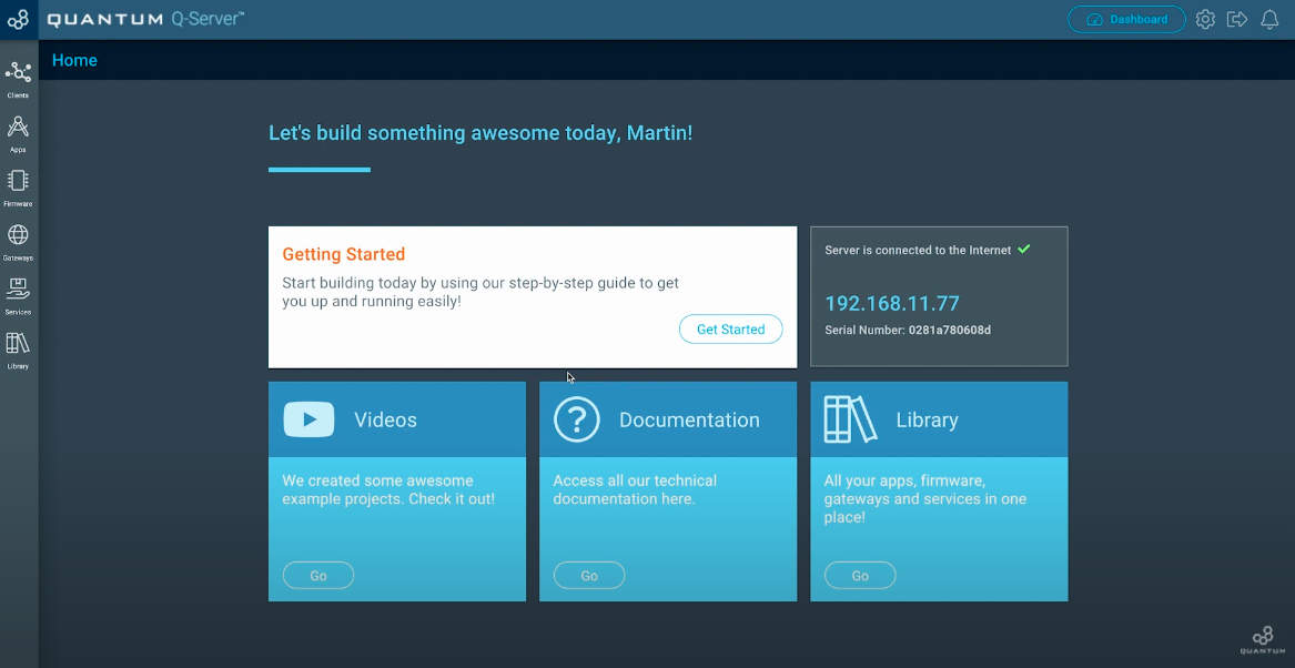
Now we want to pair the Builder Base with our Q-Server. In order to do so, go to the Homescreen of your Q-Server.
Next click on the lift side symbol labeled “Clients”. Switch to the “Unpaired” tab at the top middle of the screen.
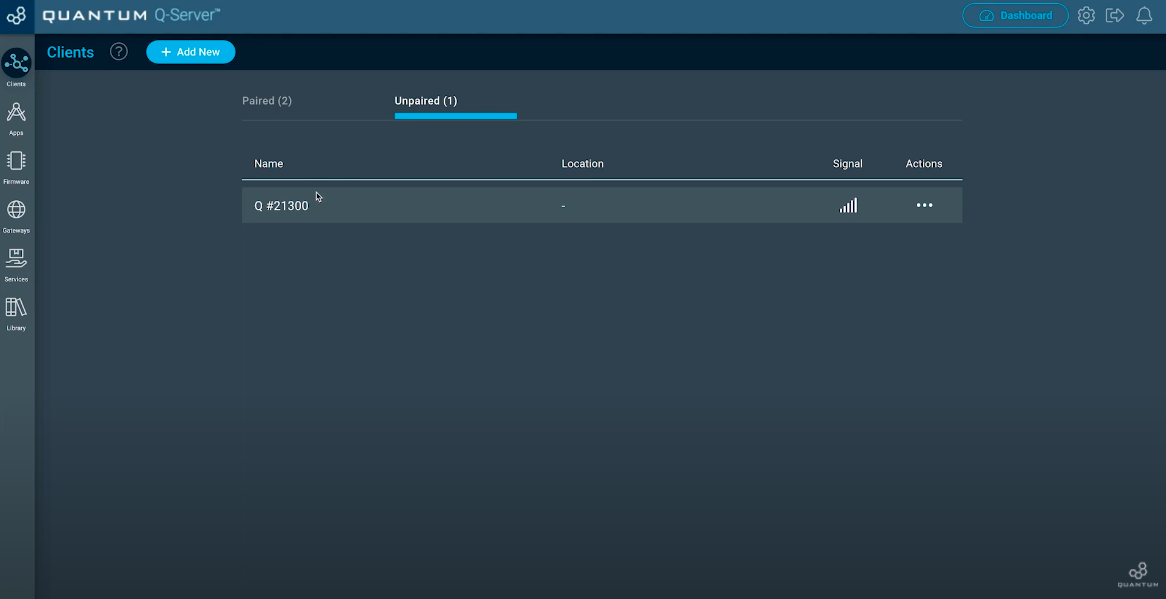
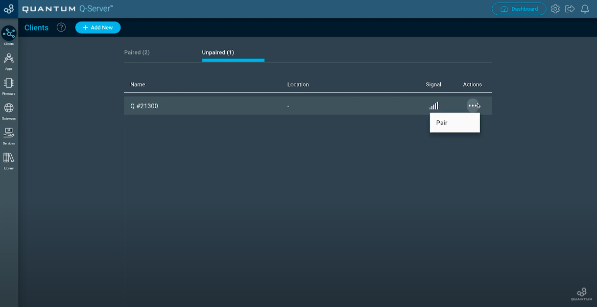
You should see your unpaired Builder Base. If not, check if you have plugged in the power supply for the Builder Base. Now move to the three dots below “Actions” and click “Pair”.
Once your Client is paired, click the “Setup” button.
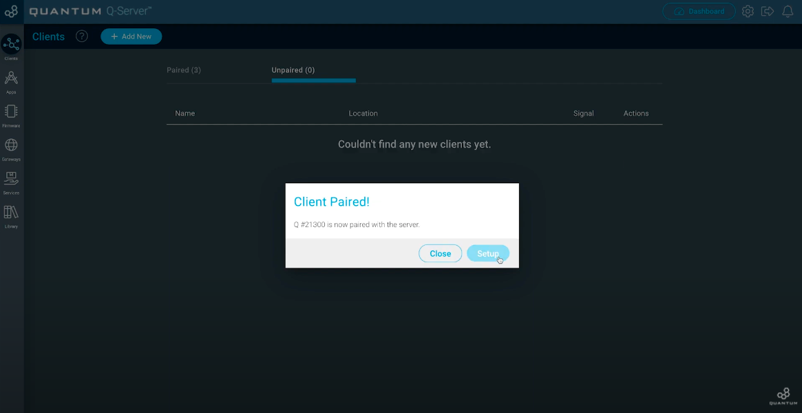
Now you can edit your Client. Give him a Name you want and also a location where you are going to use it. Hit “Save” when you finished.
Build the Firmware
| Tip |
|---|
Remember: All Apps and Firmware Files are available in the resources section at the bottom of the page! |
Here we will build two sets of firmware files: one for the Button and the other for the LED.
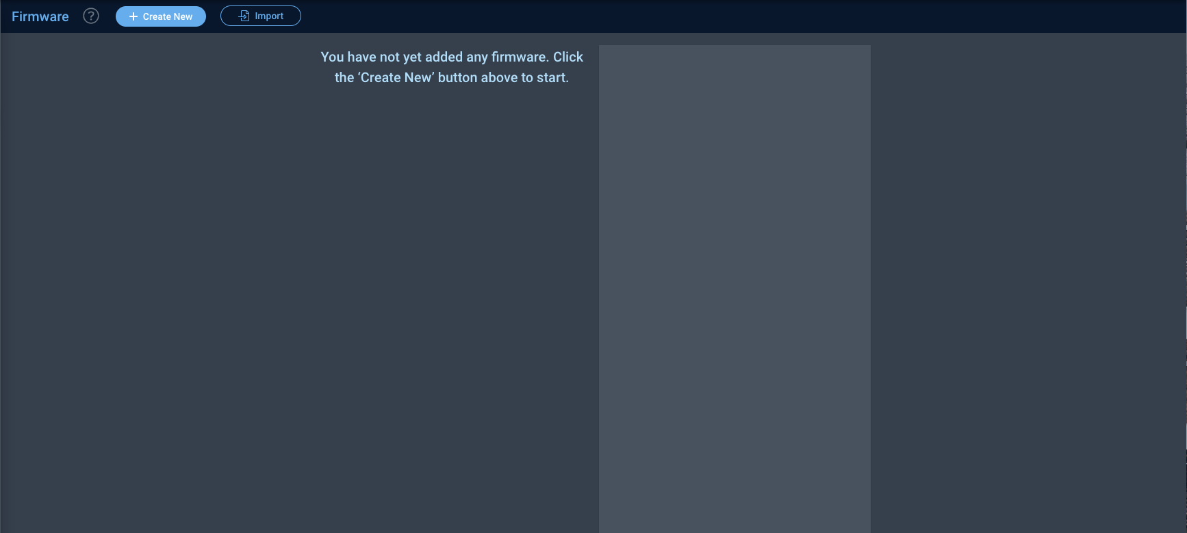
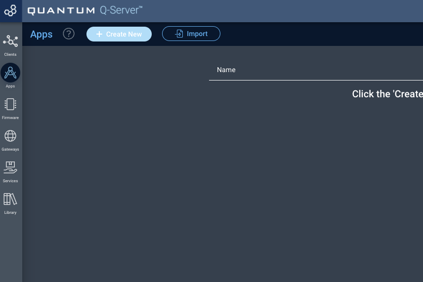
Using the toolbar located on the left hand side of the screen navigate to the firmware builder and then select “+ Create New” button to create a new firmware file.

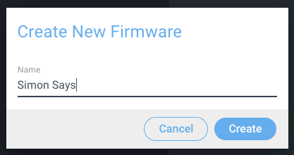
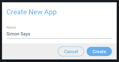
Next, name your firmware file “Simon Says” and hit “Create”.

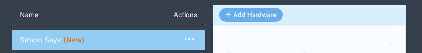
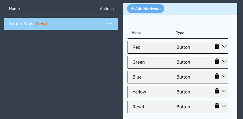
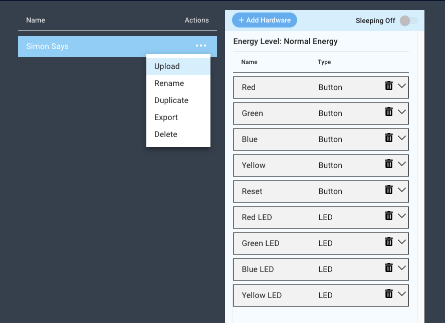
Now, click the “+ Add Hardware” button, and search for the device named “Button”.


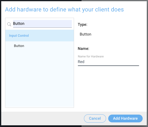
Name your device. We suggest naming this one “Red”. Add four more buttons by repeating these steps and name them: Blue, Yellow, Green, and Reset.

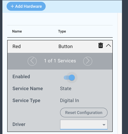
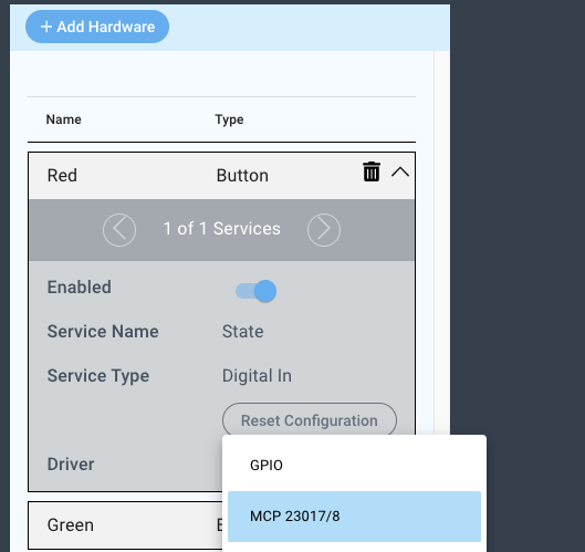
To configure the “Red” button, click on it in the device list and select the “MCP23017” driver from the driver dropdown menu.


Next, input:
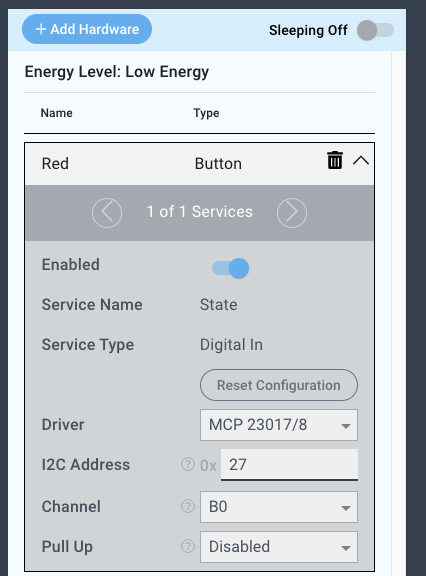
I2C: 0x27
Channel: B0
Pull Up: Disabled

Now, repeat these steps for the rest of the buttons. The only configuration that will change between them is the Channel selected for each. Here is a table for all of the button configurations:
Button | Driver | I2C Address | Channel | Pull up |
|---|---|---|---|---|
Red | MCP23017/8 | 0x27 | B0 | Disabled |
Blue | MCP23017/8 | 0x27 | B1 | Disabled |
Green | MCP23017/8 | 0x27 | B2 | Disabled |
Yellow | MCP23017/8 | 0x27 | B3 | Disabled |
Reset | MCP23017/8 | 0x27 | B4 | Disabled |
With the buttons configured, let’s now add the LEDs. Again, click the “+Add Hardware” button, search for the LED device, and give it a name. Name the LED “Red LED”, and select the “Add Hardware” button.


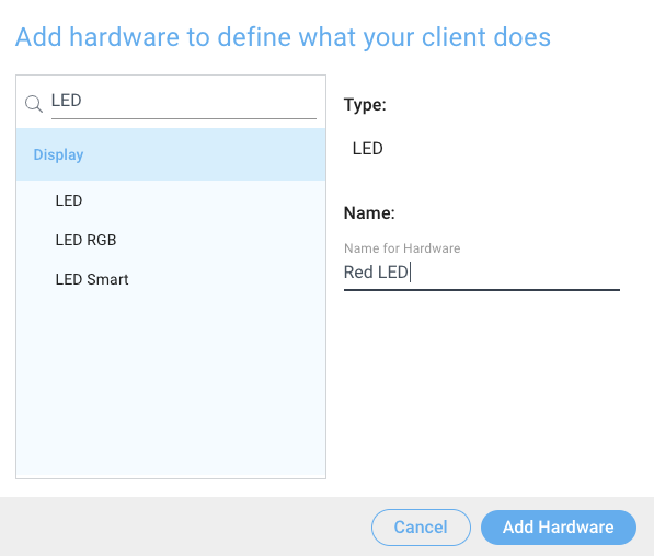
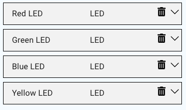
Add three more LEDs by repeating these steps and name them: Green LED, Blue LED, and Yellow LED.

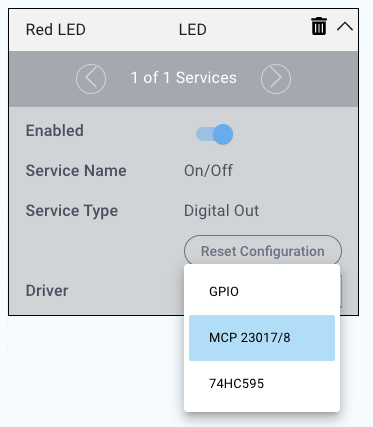
Click on the “Red LED” device and select the “MCP23017/8” driver under the driver dropdown menu.


For this driver we will select:
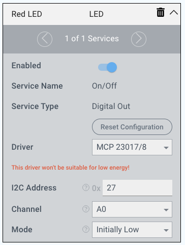
I2C Address: 0x27
Channel: A0
Mode: Initially low

Now, repeat these steps for the rest of the LEDs. The only configuration that will change between them is the channel selected for each. Here is a table for all of the LED configurations:
LED | Driver | I2C Address | Channel | Pull up |
|---|---|---|---|---|
Red LED | MCP23017/8 | 0x27 | A0 | Initially Low |
Green LED | MCP23017/8 | 0x27 | A1 | Initially Low |
Blue LED | MCP23017/8 | 0x27 | A2 | Initially Low |
Yellow LED | MCP23017/8 | 0x27 | A3 | Initially Low |
With the configurations set you can now save and upload your firmware.


Build the App
| Tip |
|---|
Remember: All Apps and Firmware Files are available in the resources section at the bottom of the page! |
For this project we will walk you through the objects used and the logic involved. You can choose to follow along, or you can download the app and import it onto your server.
Once there, click “+ Create New”.

Name your app, and hit “Create”.

You will be redirected to the canvas where you can build the app.

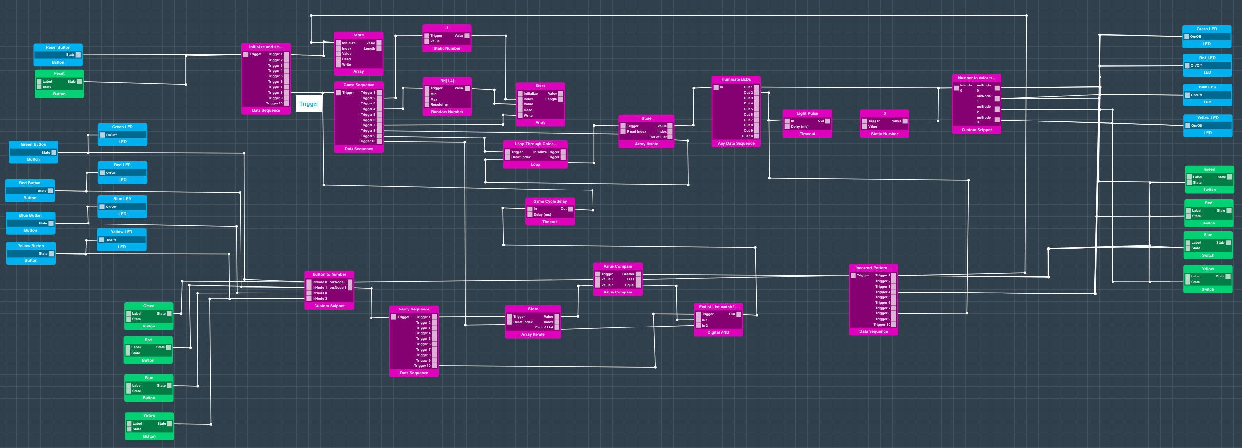
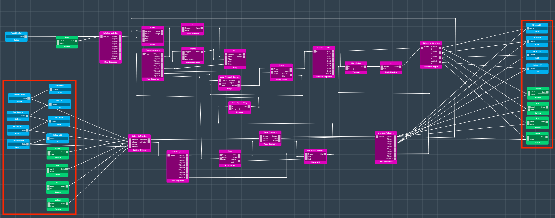
This first section consists of both a physical reset button and a dashboard button. Both perform the same function of initializing the “Store” array and triggering the game sequence.

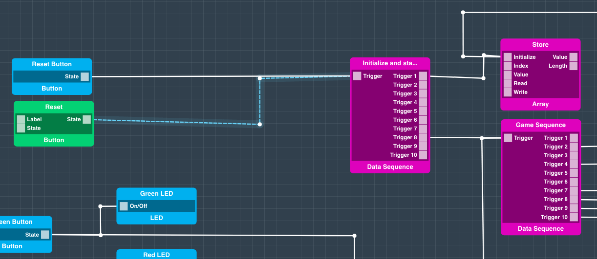
The Game sequence consists of indexing the “Store” Array to -1. This index will place the value input at the end of the array. The Random Number code object is then triggered. This picks a random number between 1 and 4. This value is then passed and written to the store array.

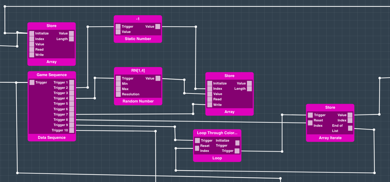
After the value is written to the array, you can see that from trigger port 8 the “Store” Array Iterate object’s Index is reset and then from trigger port 9 the Loop object is triggered. Upon triggering, the Loop triggers the Array iterate object to output the values of the Array. These values are then passed to the “Illuminate LEDs” Any Data Sequence object. Once the end of the array is reached, the index on the Loop is reset.

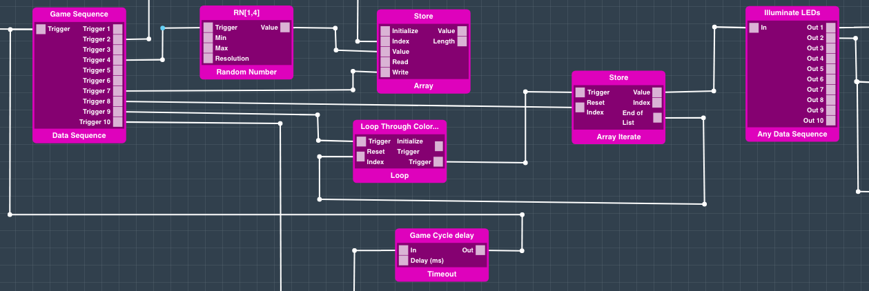
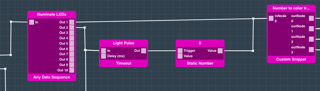
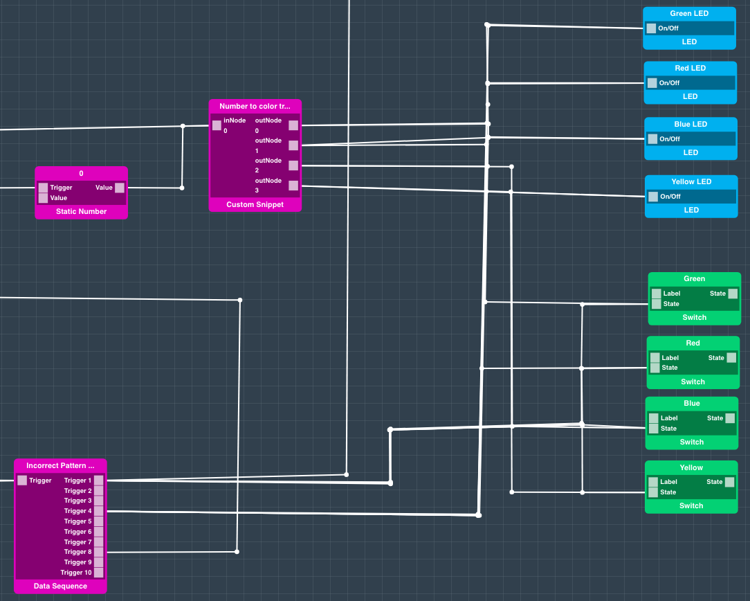
When the values are passed from the Array Iterate object to the Any Data Sequence object they are passed to a custom snippet named “Number to Color Translate”. The numbers that can be passed are 0-4. Each number corresponds to a different color. 1 is Green, 2 is Red, 3 is Blue, 4 is Yellow, and 0 outputs “false” from all output ports.

You can see the code here:
| Code Block | ||
|---|---|---|
| ||
switch(inPorts[0].value){
  case 0:{
    return [false,false,false,false];
  }; break;
  case 1:{
    return [true,false,false,false];
  }; break;
  case 2:{
    return [false,true,false,false];
  }; break;
  case 3:{
    return [false,false,true,false];
  }; break;
  case 4:{
    return [false,false,false,true];
  }; break;
  default: break;
} |
The number passed to the snippet dictates which output port will send out a trigger signal. Once this signal is passed it will trigger the LED and Button interface objects that are connected to it.
So, for example, if a 2 is passed to the custom snippet the second output port, and only the second output port, will send out a signal.
Also connected to the output ports on the sequence are a timeout and static number objects. The purpose of this is to shutoff the LEDs once they have been triggered. The timeout allows the LED to stay on for 500ms before a 0 is sent to the “Number to Color Translate object” which turns off all output ports.

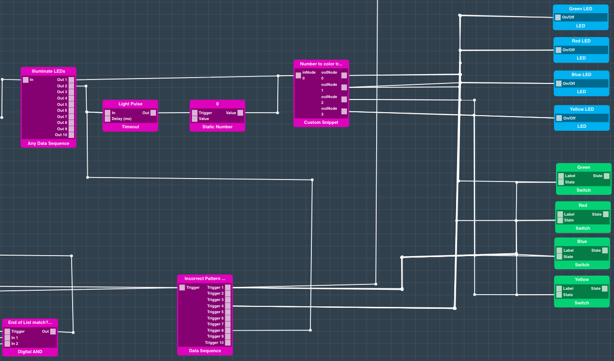
That’s how the colors for the game are selected and stored. Now we will show you how the logic determines if the right sequence of color inputs have been selected by the user.

| Info |
|---|
It is important to note that these LED objects are used twice in this application, but due to the mapping they all correspond to the same LEDs |
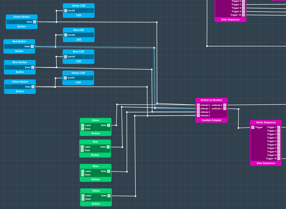
Here we have all of the button hardware components connected to the LEDs. We configured this so that every time the user presses a button the corresponding LED will be illuminated. So if the user presses the button that corresponds to the green LED, the green LED will illuminate for the interval that the button is depressed.
You can also see that the buttons are connected to a custom snippet. This is essentially the reverse of the other custom snippet used above. Each button is connected to an individual input port on the snippet. Depending upon which port the signal is received a number in the range of 1-4 is output by the snippet.
You can see the custom snippet code here:
| Code Block | ||
|---|---|---|
| ||
return [trigger+1, new Date()] |
What this code does is return the number of the output port ([0,3] + 1) (to make it 1 through 4) that the signal was received from, and a “new Date()” which acts as a trigger. The number is output through the first output port, and the trigger through the second.

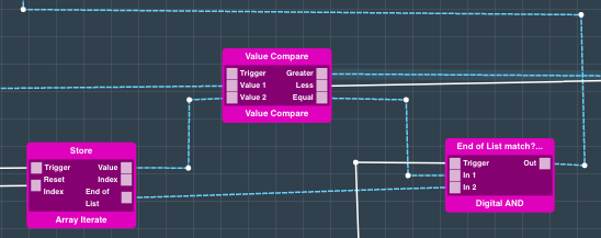
These outputs are then used to verify that the input given is correct. For every button pressed the “Verify Sequence” data sequence is triggered. This triggers the Array Iterate object for the “Store” Array, passing the first value to the Value Compare object. The Value from the “Button to Number” custom snippet is also passed to the same Value Compare object. If the values are equal, the Value Compare object will send a signal to the Digital AND object below.

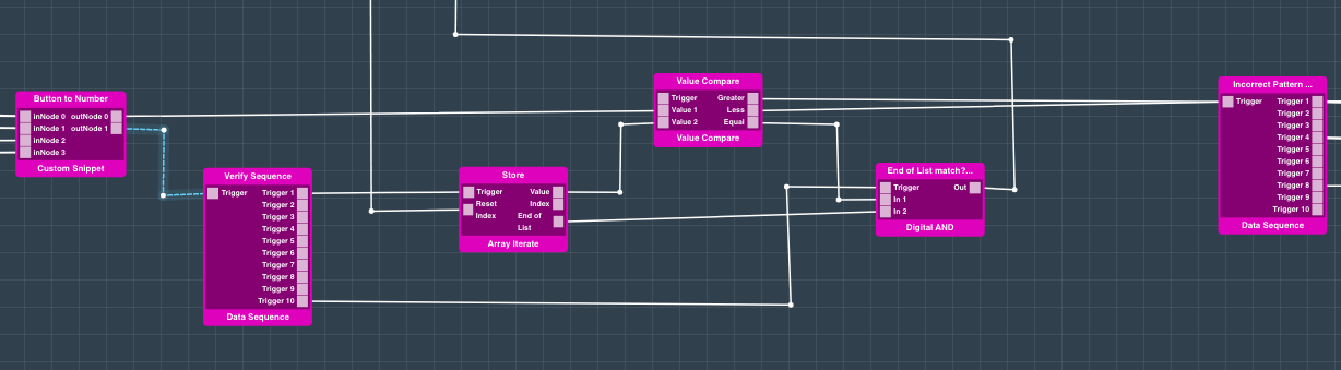
Now if the Array Iterate object has reached the end of the list and all values entered match the values stored in the array, the Digital AND will trigger and the game sequence will be restarted.
You can see this logic path with the lines selected in blue.

| Info |
|---|
The “Value 1” port on the value compare object is set to “Trigger” under the properties panel. This is important as the comparison needs to be triggered every time a button is depressed |
However, if one of the values entered is incorrect the “Greater” and “Less” output ports on the Value compare port will trigger.

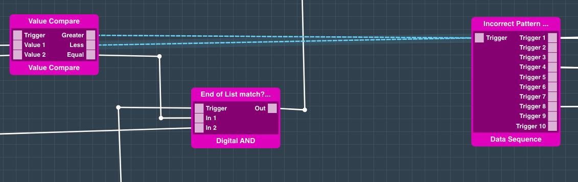
This then triggers the “Incorrect Pattern” data sequence. This sequence causes the LEDs to turn on and off in quick succession, and re-initializes the “Store” array; effectively priming the array for a new game.

This sums up the basic logic behind the Simon Says project.
Map the Hardware
Navigate back to the applications page.
Find your “Simon Says” app and hit the play button.

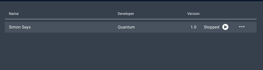
A list containing all of the devices is your application will expand.

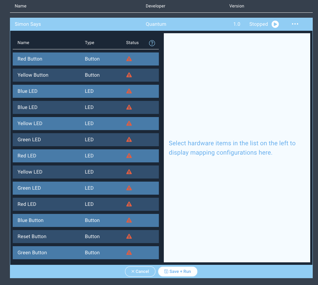
Next click on the “Red Button” device and the client dropdown menu will appear on the right.
Select the “Simon Says - Red” driver from the dropdown menu and hit “Done”.

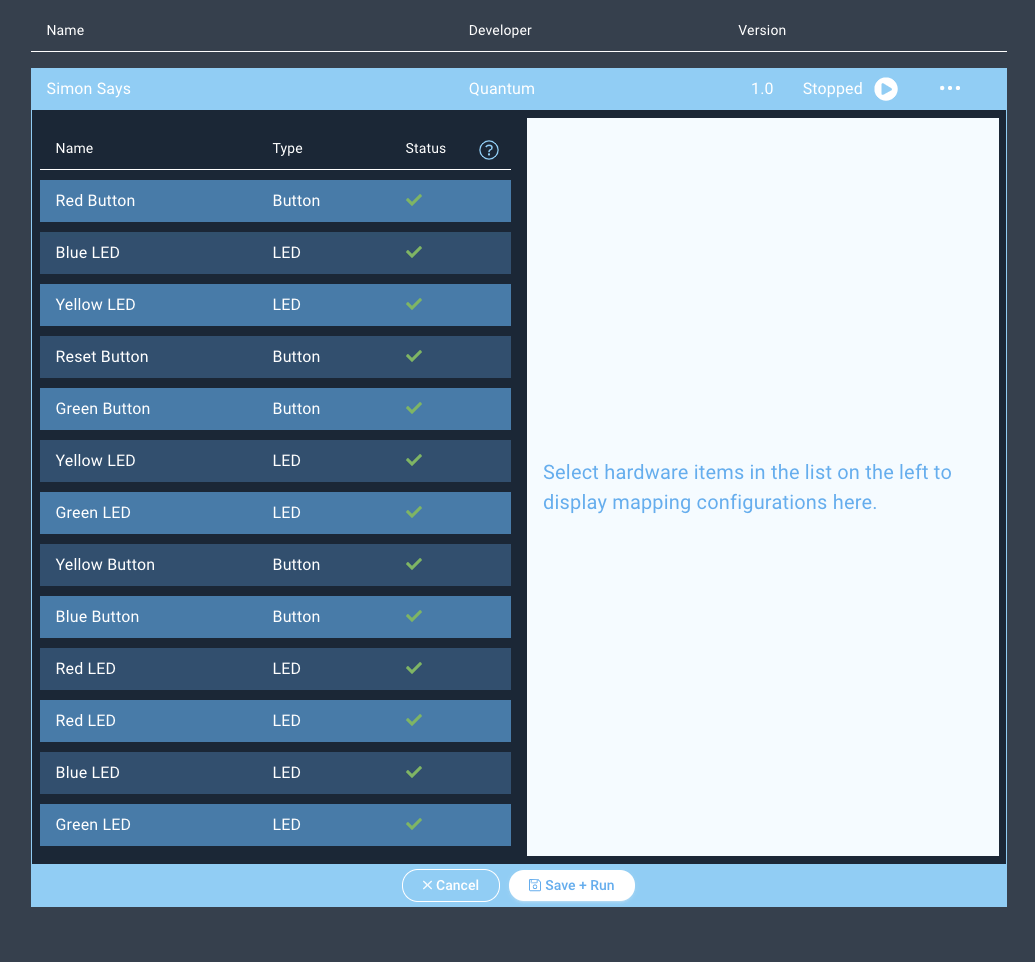
You should now go down and map all of the devices for the application. Ensure to match the objects to the drivers carefully. The color for the buttons and LEDs need to match the colors described in the drivers - e.g. Blue LED → Simon Says - Blue LED.
| Info |
|---|
Note that you will be mapping each color of LED twice. This is because the Application accesses the same LEDs from two different code objects. |
Notice how the status symbols have changed to green checkmarks.

Run the App!
Congratulations on building the Simon Says project. It is now time to run it!
Hit “Save + Run”.

Voila! Your Simon Says project is now complete.

Use the DIY Kit
You can also build this project with one of our DIY kits!
Check out the following project section of the Simon Game DIY Kit page to find out how.
Gallery


Resources
AppApplication |
| ||||
|---|---|---|---|---|---|
Firmware |
| ||||
Fritzing |
|