| Table of Contents |
|---|
Introduction
The GPIO Floating (Low Energy) driver is used to detect the level of a digital signal on a selected pin on devices in Ultra Low Energy mode. This driver is floating, but supposed to be used with an external pull down resistor. Current through the resistor is only going to flow in the moment the pin is actually read. This saves more energy because there is no current drawn from the resistor constantly in case of the contact being closed for a longer period of time. The pull down resistor can be selected depending on the application this driver is used in, to preserve even more energy by choosing the highest resistor possible.
Driver Parameters
The GPIO driver for Digital Inputs has three parameters that have to be configured:
Pin
This is the pin sensing the input, any of the GP pins is suitable for this selection if not already used for other drivers.
Debouncing
What is Debouncing
Pushbuttons often generate spurious open/close transitions when pressed, due to mechanical and physical issues. These transitions may be read as multiple presses in a very short period of time which can fool the program. Debouncing puts a physical delay between the readings so it insures that the button is really pressed again. Without debouncing, pressing the button once may cause an unpredictable result.
Possible Configurations
Debouncing Enabled:
The pin is debounced internally and will disregard mechanical feedback during a single button push (see: Use the GPIO Floating (Low Energy) driver )
Debouncing Disabled:
The pin can be debounced externally with a debouncing circuit fitting the application (see: https://quantumintegrate.atlassian.net/wiki/spaces/QFR/pages/285442275/Use+the+GPIO+Floating+Low+Energy+driver#Debouncing-Disabled )
The pin can just be left as is but unpredictable presses might occur (see: https://quantumintegrate.atlassian.net/wiki/spaces/QFR/pages/285442275/Use+the+GPIO+Floating+Low+Energy+driver#Debouncing-Disabled-with-External-debouncing )
Power Pin
This pin is held low during idle operation and is driven high in the moment of reading. Since the data pin is supposed to be pulled low, this pin provides the opposite bias only in the moment of reading data and saves more energy this way.
Wiring
Debouncing Enabled
The pin is pulled down externally with a 10000Ω resistor. The power pin supplies a high state during data capture and when the button is pressed, the high state is read by the client
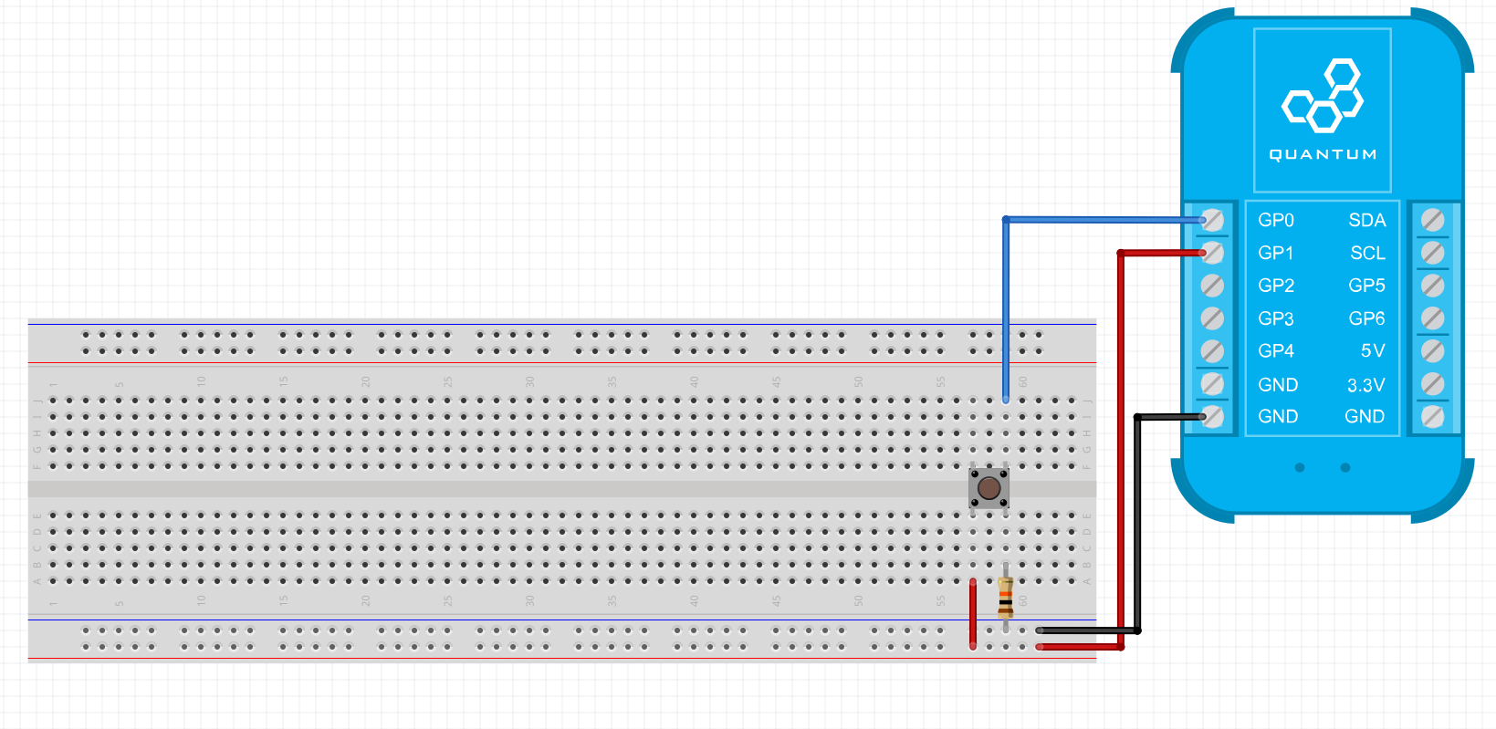
Breadboard
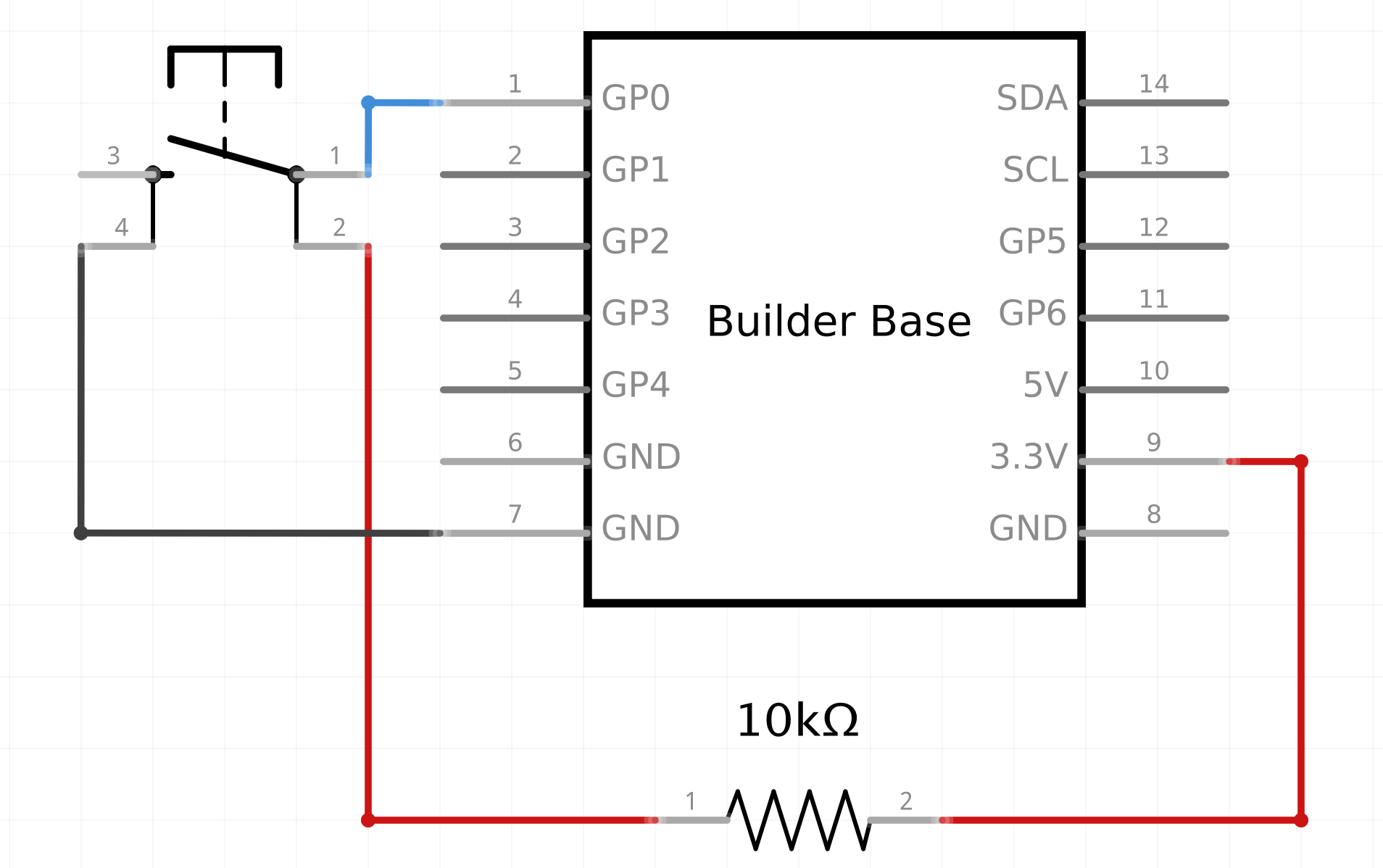
Schematic
Used Pins
Used Pins | Description |
|---|---|
Any GP pin (Pin) | This pin reads the digital level and is pulled down internally |
Any GP pin (Power Pin) | This pin provides a low level normally and a high level when the data pin is read |
Debouncing Disabled
Just like the circuit above. The button is not debounced internally as described in the parameter description and mechanical feedback is not disregarded
Debouncing Disabled with External debouncing
The pin is pulled down externally with a 10000Ω resistor and externally debounced with an RC filter. The power pin supplies a high state during data capture and when the button is pressed, the high state is read by the client
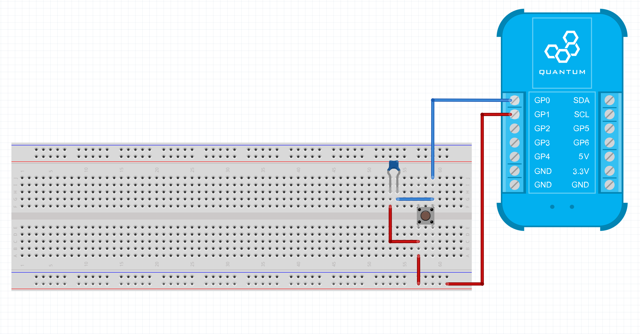
Breadboard
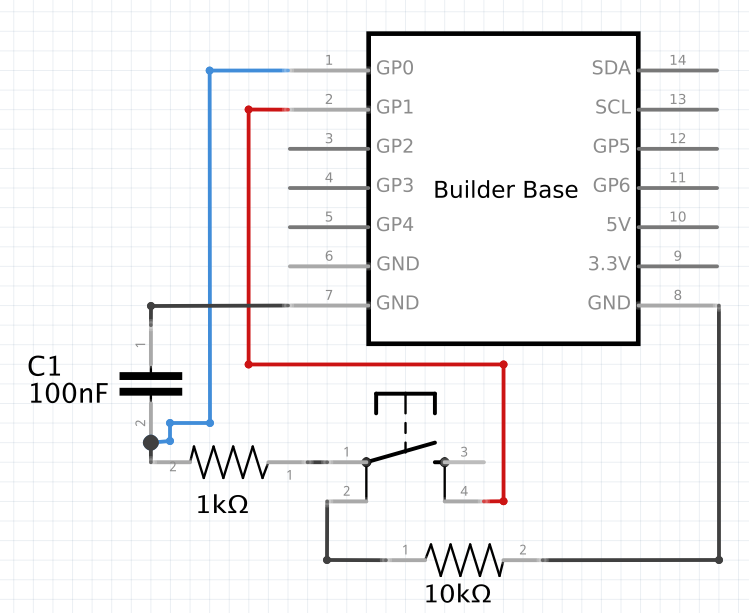
Schematic
Used Pins
Used Pins | Description |
|---|---|
Any GP pin (Pin) | This pin reads the digital level and is pulled down internally |
Any GP pin (Supply Pin) | This pin provides a low level normally and a high level when the data pin is read |
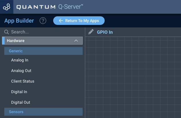
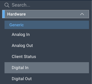
How to write an App
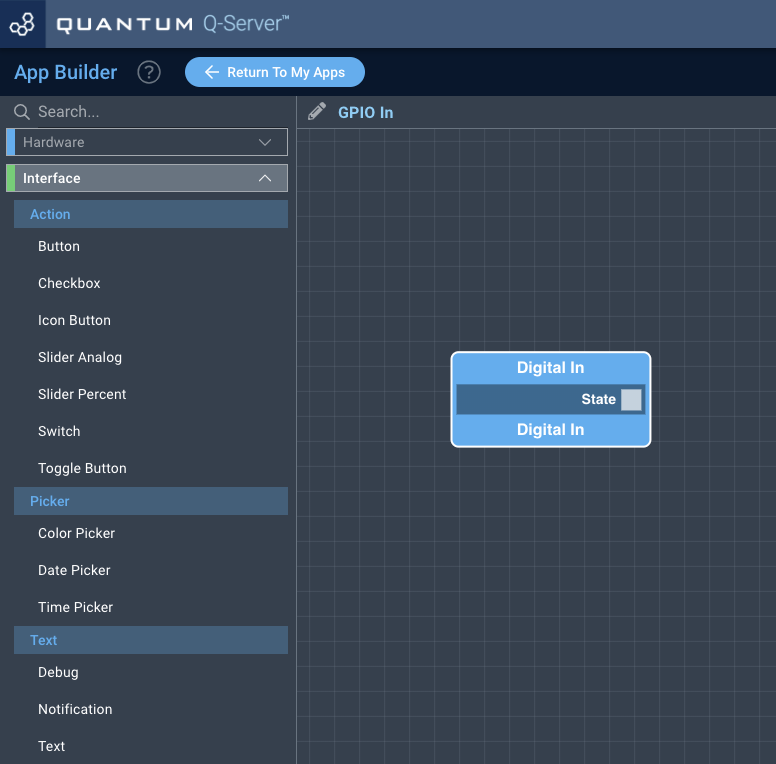
Navigate to the App Builder and create a new application. You can find the “Digital In” code object under the “Hardware” Tab in the object drop down menu on the left, or you can also use the search bar.
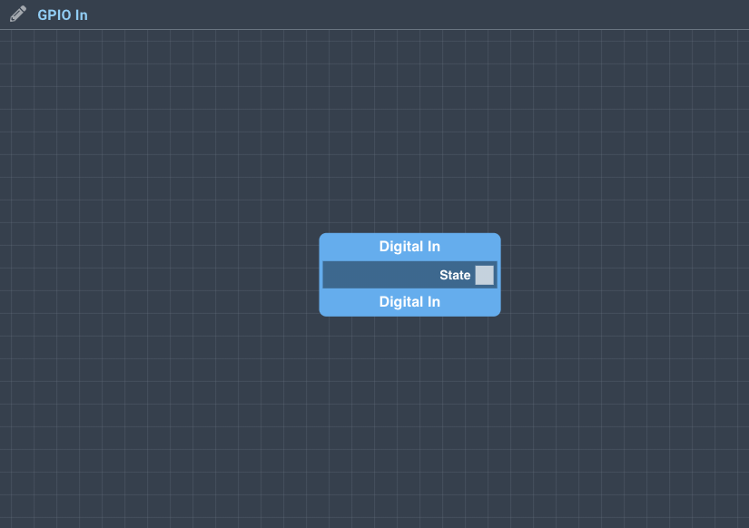
Drag the “Digital In” Object onto the canvas.
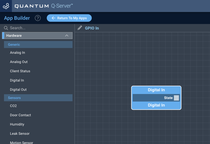
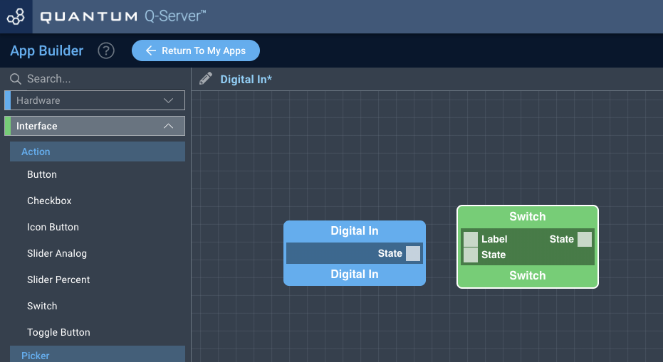
Next, locate the “Switch” Object under the “Interface” tab and drag it onto the canvas.
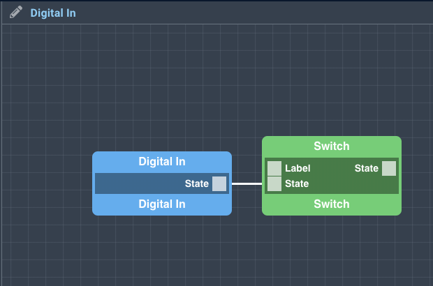
Finally, connect the “State” port from the Digital In Object to the “State” port on the Switch Object, and save your application.
How to create a firmware
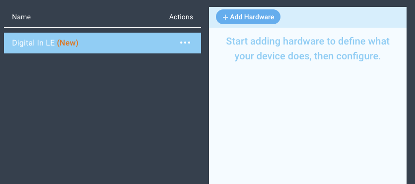
Navigate to the Firmware Builder and create a new firmware file.
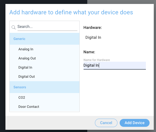
Click the “+ Add Hardware” button which will open a modal window. Scroll down in the list to find the “Generic” section and select the “Digital In” hardware option.
Give your device a name, and click “Add Device”
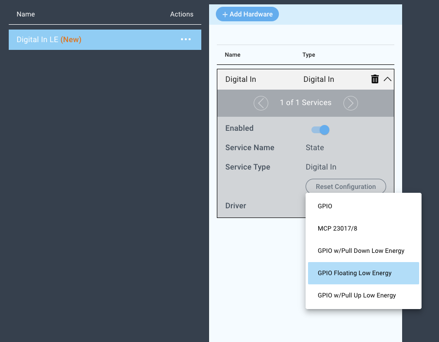
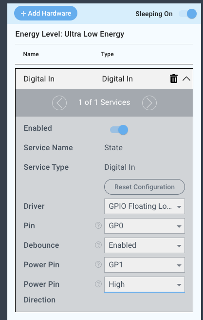
Next, select the “GPIO w/Pull Down Floating Low Energy” driver under the driver dropdown menu, set the Pin, Button Debouncing, the power pin, and the power pin direction.
For this example we select:
Pin: GP0
Debouncing: DisabledEnabled
Power Pin: GP1
Power Pin Direction: High


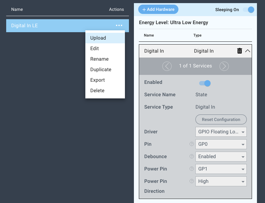
You may now save your firmware file and upload it to one of your clients.

Supported Hardware
Buttons
Contact sensors
Anything providing a digital signal
Downloads
Apps
| View file | ||
|---|---|---|
|
Firmware
| View file | ||
|---|---|---|
|
Assets
| View file | ||
|---|---|---|
|