| Table of Contents |
|---|
Introduction
The 4x3 button keypad driver can connect buttons from a generic 4x3 keypad to the Builder Base. The driver represents a single button on the keypad. This way a desired amount of buttons or the entire keypad can be added to the system.
Driver Parameters
The GPIO driver for Digital Inputs has two parameters that have to be configured:
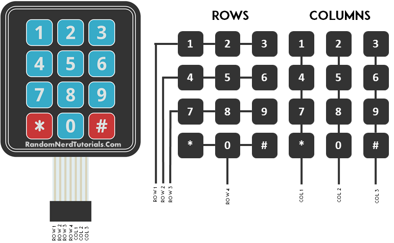
Row Pin
This is the pin connected to the row of the button we want to read. There are 4 rows above each other and the most left pin is representing the top row
Column Pin
This is the pin connected to the column of the button we want to read. There are 3 columns next to each other and the 5th pin from the left is representing the most left column
Wiring
The wiring of the 4x3 button keypad can be found below:
Example
The top row is connected to GP0 and the most left column is connected to the GP1. With this setup we would read the state of the “1“ button.
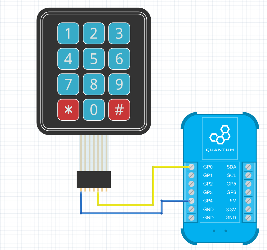
Breadboard
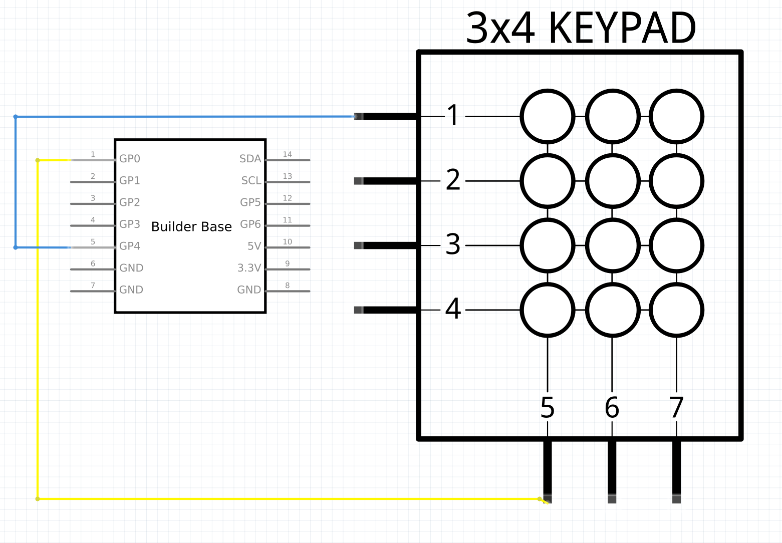
Schematic
Used Pins
Used Pins | Description |
|---|---|
Any GP4 (can be any GP pin) | This pin is connected to the row of the button we want to read |
Any GP0 (can be any GP pin) | This pin is connected to the column of the button we want to read |