d
Introduction
The MCP23017/8 driver for 7-Segment displays is used in conjunction with a generic 7 segment brick and an MCP 23017/8 GPIO expander. The LEDs of the brick are driven by the GPIO expansion output pins which are driven by the Builder Base.
Driver Parameters
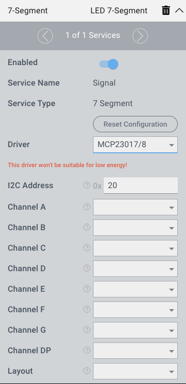
The BCD driver for 7-Segment displays has ten parameters that need to be configured:
I2C Address
This is the address the device is being referenced by on the I2C bus. The two chips have a different way of being addressed:
MCP23017
The MCP23017 has 3 address pins (A0, A1, A2). To select the correct address, please view the following table:
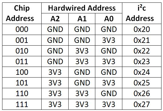
More information about addressing can be found in the datasheet
MCP23018
The MCP23018 has only one address pin (ADDR). The address selection here is achieved by feeding a voltage level between voltage and ground to the ADDR pin. To select the correct address, please view the following table:
Address | Ideal level | Permitted range | R1 | R2 | Actual level |
|---|---|---|---|---|---|
0x20 | 1/16 = 0.625 | 0 – 0.0875 | 4K7 | Open circuit | 0 |
0x21 | 3/16 = 0.1875 | 0.1625 – 0.2125 | 1K | 4K7 in parallel with 56K | 0.1726 – 0.2031 |
0x22 | 5/16 = 0.3125 | 0.2875 – 0.3375 | 1K5 | 3K3 | 0.2914 – 0.3344 |
0x23 | 7/16 = 0.4375 | 0.4125 – 0.4625 | 2K2 in parallel with 47K | 2K7 | 0.4132 – 0.4625 |
0x24 | 9/16 = 0.5625 | 0.5375 – 0.5875 | 2K7 | 2K2 in parallel with 47K | 0.5375 – 0.5868 |
0x25 | 11/16 = 0.6875 | 0.6625 – 0.7125 | 3K3 | 1K5 | 0.6656 – 0.7086 |
0x26 | 13/16 = 0.8125 | 0.7875 – 0.8375 | 4K7 in parallel with 56K | 1K | 0.7968 – 0.8274 |
0x27 | 5/16 = 0.9375 | 0.9125 – 1 | Open circuit | 4K7 | 1 |
The resistors are from the E12 series with a tolerance of 5% max
More information about addressing can be found in the datasheet
Channel A
This is the channel connected to the A segment of the brick.
Channel B
This is the channel connected to the B segment of the brick.
Channel C
This is the channel connected to the C segment of the brick.
Channel D
This is the channel connected to the D segment of the brick.
Channel E
This is the channel connected to the E segment of the brick.
Channel F
This is the channel connected to the F segment of the brick.
Channel G
This is the channel connected to the G segment of the brick.
Channel DP
This is the channel connected to the DP segment of the brick.
Layout
This determines whether the common connection is to GND or 3.3V. Options are common anode (see: https://quantumintegrate.atlassian.net/wiki/spaces/QFR/pages/145785720/Use+the+MCP23017+8+driver+for+7-Segment+displays#Common-Anode ) or common cathode (see: https://quantumintegrate.atlassian.net/wiki/spaces/QFR/pages/145785720/Use+the+MCP23017+8+driver+for+7-Segment+displays#Common-Cathode ).
Wiring
The two version of this drivers have different pinouts which can be found below
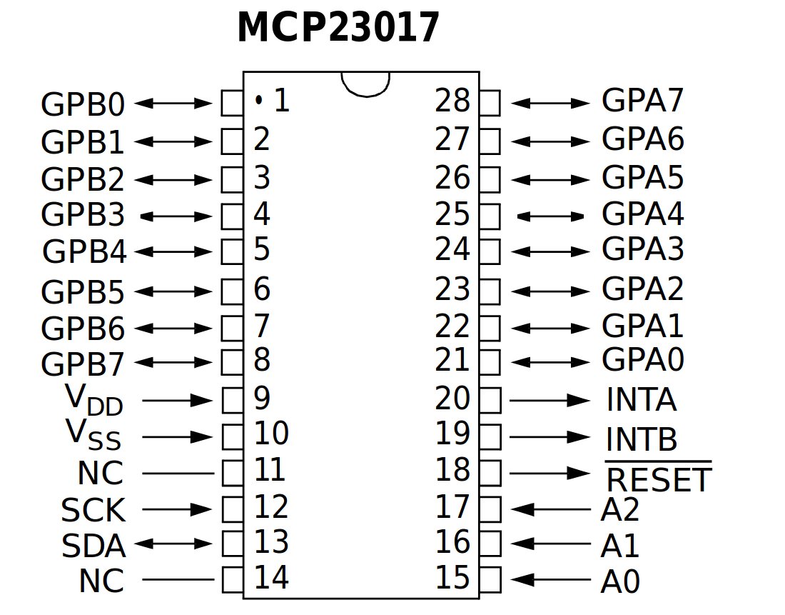
MCP23017
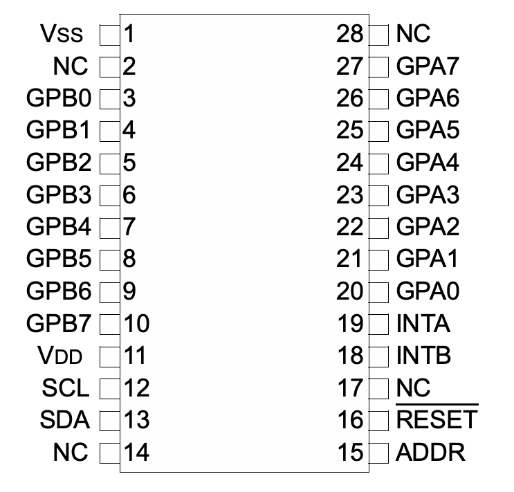
MCP23018
For the following wiring sample we concentrate on the MCP23017. The change to the MCP23018 can be made by adjusting the addressing and relocating all pins used in a sample and wiring them up to the appropriate location on the MCP23018.
Common Anode
The chip is connected to address 0x20 of the I2C bus because all address lines are pulled low. The common anode of the brick is connected to 3.3V.
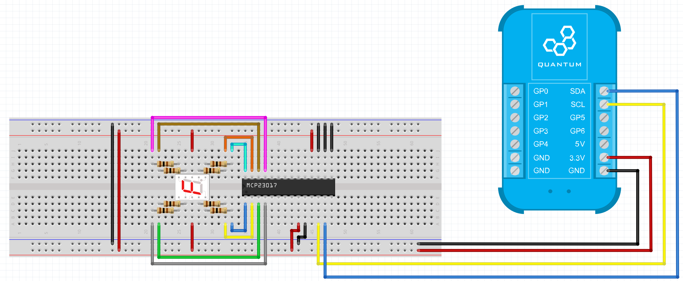
Breadboard
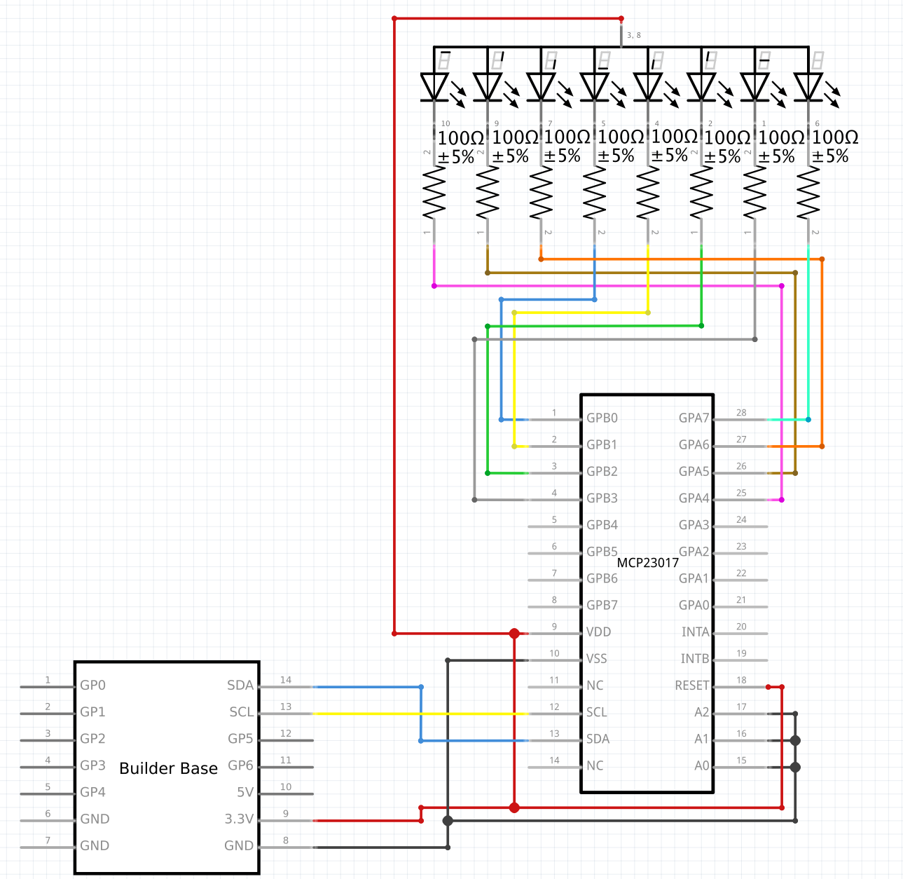
Schematic
Used Pins
Used Pins | Description |
|---|---|
3V3 | The voltage level for the assembly |
GND | The ground potential for the assembly |
SDA | The I2C data line |
SCL | The I2C clock line |
Common Cathode
The chip is connected to address 0x20 of the I2C bus because all address lines are pulled low. The common cathode of the brick is connected to GND.
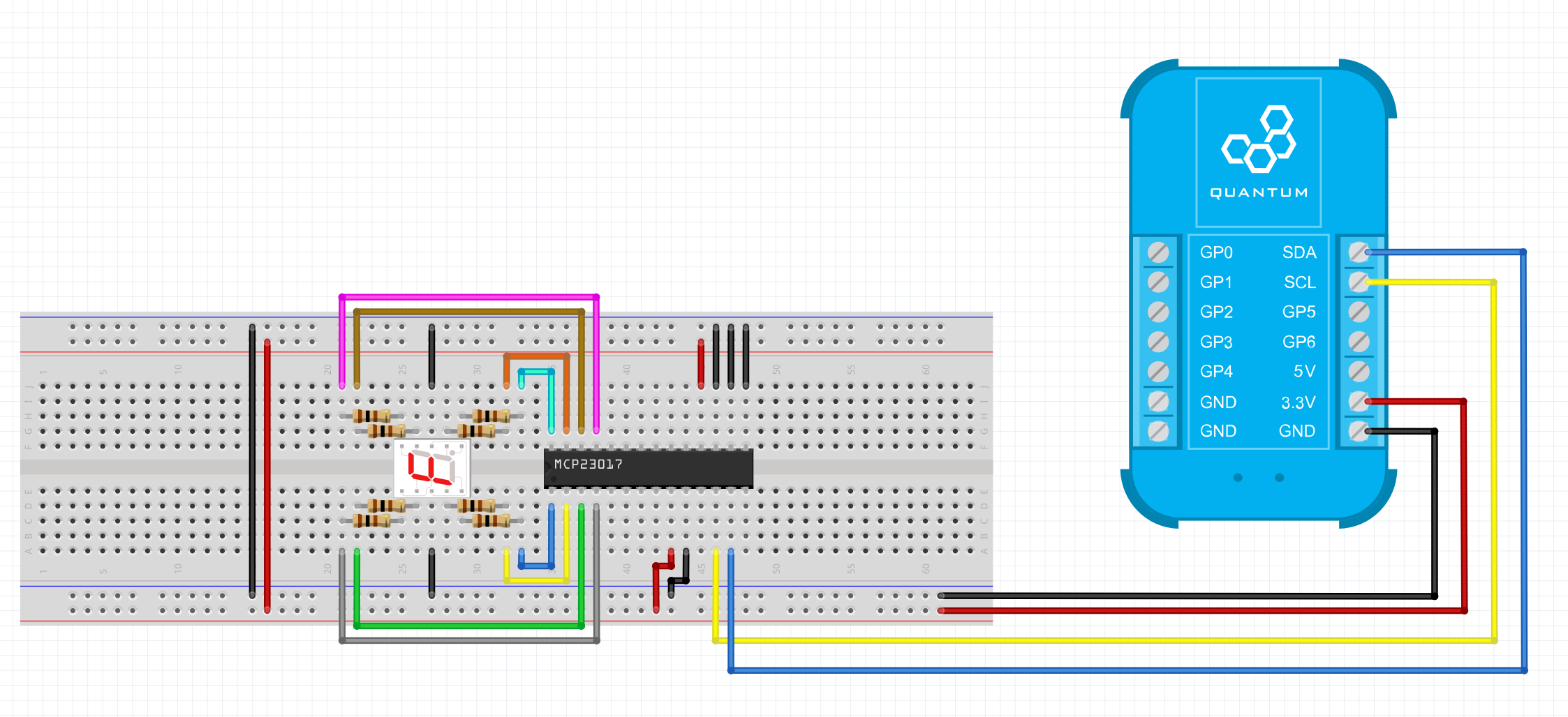
Breadboard
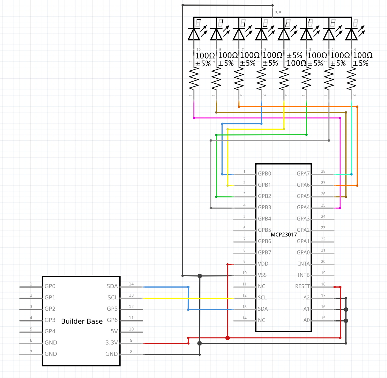
Schematic
Used Pins
Used Pins | Description |
|---|---|
3V3 | The voltage level for the assembly |
GND | The ground potential for the assembly |
SDA | The I2C data line |
SCL | The I2C clock line |
How to write an App
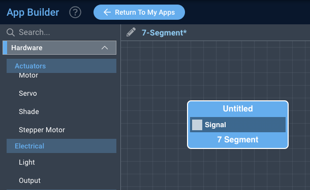
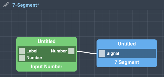
Navigate to the App Builder and create a new application. You can find the “7-Segment” code object under the “Hardware” Tab in the object drop down menu on the left, or you can also use the search bar.
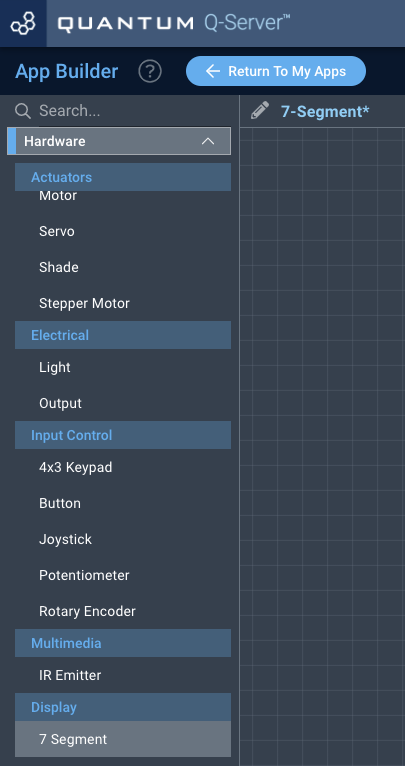
Drag the “7-Segment” object onto the canvas.
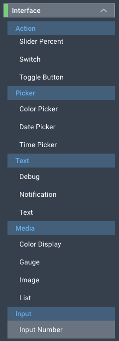
Next, located under the interface tab find the “Input Number” object and drag it onto the canvas.
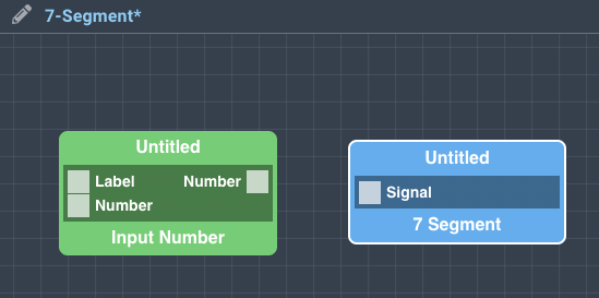
Finally, connect the number port from the “Input Number” object to the “Signal” port on the 7-Segment object, and save your application.
How to create a firmware
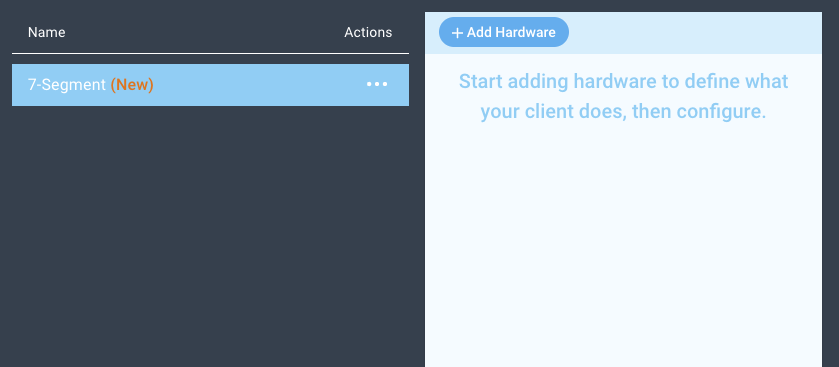
Navigate to the Firmware Builder and create a new firmware file.
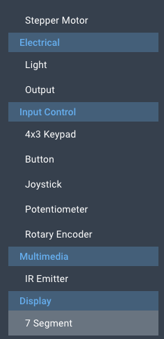
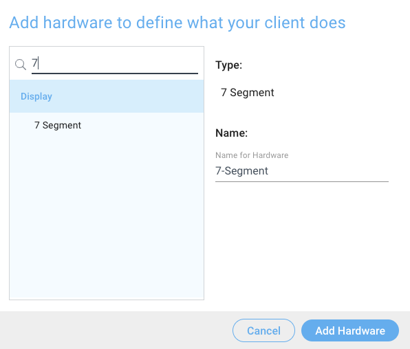
Click the “+ Add Hardware” button which will open a modal window. Scroll down in the list to find the “Display” section and select the “7-Segment” hardware option.
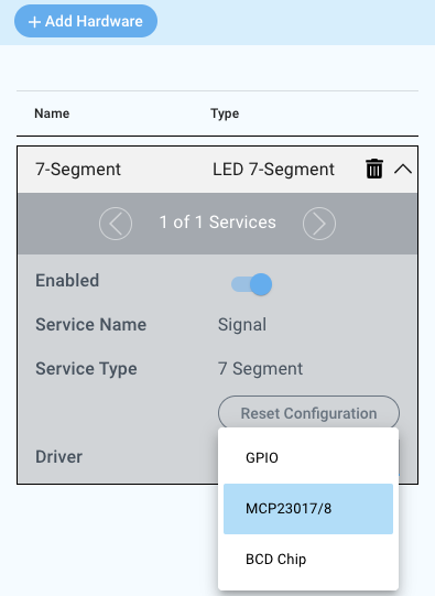
Give your device a name, and click “Add Hardware”
Next, select the “Dimmed” “MCP 23017/8” driver under the driver dropdown menu.
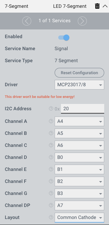
For this example we select:
I2C Address: 0x20
Channel A: A4
Channel B: A5
Channel C: A6
Channel D: B0
Channel E: B1
Channel F: B2
Channel G: B3
Channel DP: A7
Layout: Common Cathode
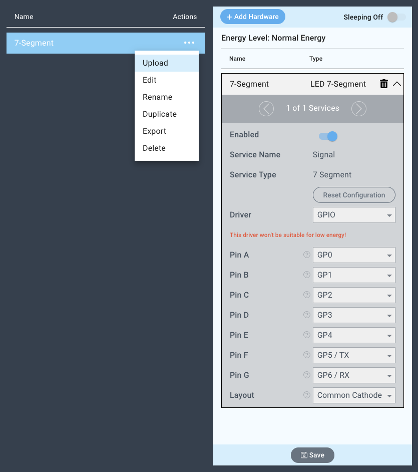
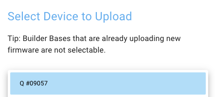
You may now save your firmware file and upload it to one of your clients.
Supported Hardware
7-Segment Displays
Downloads
Apps
| View file | ||
|---|---|---|
|
Firmware
| View file | ||
|---|---|---|
|
Assets