| Table of Contents |
|---|
Overview
| Widget Connector | ||||||||||
|---|---|---|---|---|---|---|---|---|---|---|
|
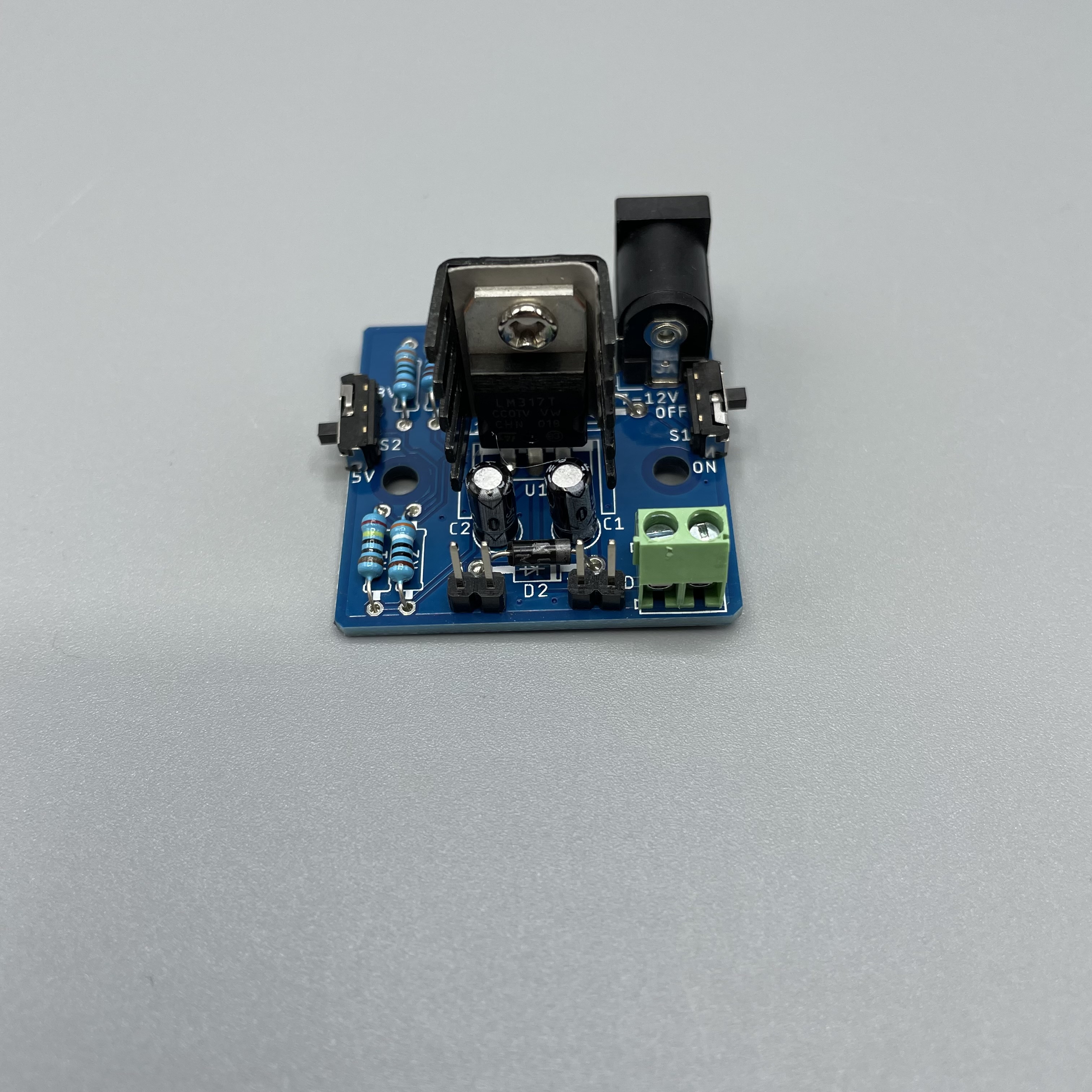
A Power Supply DIY Kit that can be used to power the Q-Client Builder Base or any of your other projects from a 9V battery. 5V and 3.3V as available as output voltagesprojects The full DIY Kit can be purchased here. The Power Supply kit is a handy device that can be used in a multitude of projects. You can use it to wirelessly power your Builder Base and all connected components. The power supply accepts 7-12V batteries via a 2.1mm barrel jack and regulates the voltage down to 5V or 3.3V. The power supply can connect to the Builder Base via the 3.3V or 5V ports.
|
|
|
|
|
Required hardware
|
|
Hardware Components
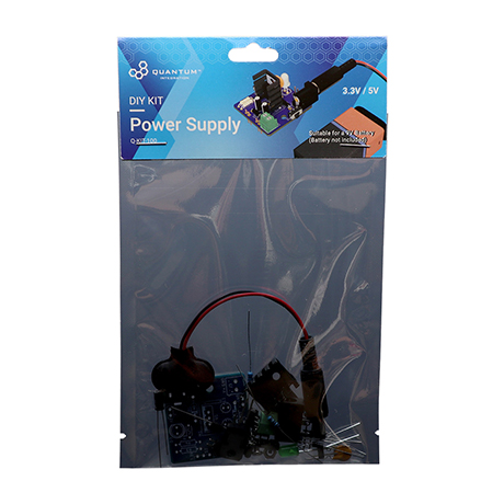
The full DIY Kit can be purchased hereThe components are part of the DIY Kit or can be sourced separately with help of the BOM:
| View file | ||
|---|---|---|
|
| View file | ||
|---|---|---|
|
Picture | Name | Designator | Quantity |
|---|
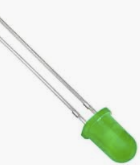
Radial LED (5mm) | D3 | 1 | |
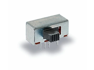 | Sliding Switch | S1, S2 | 2 |
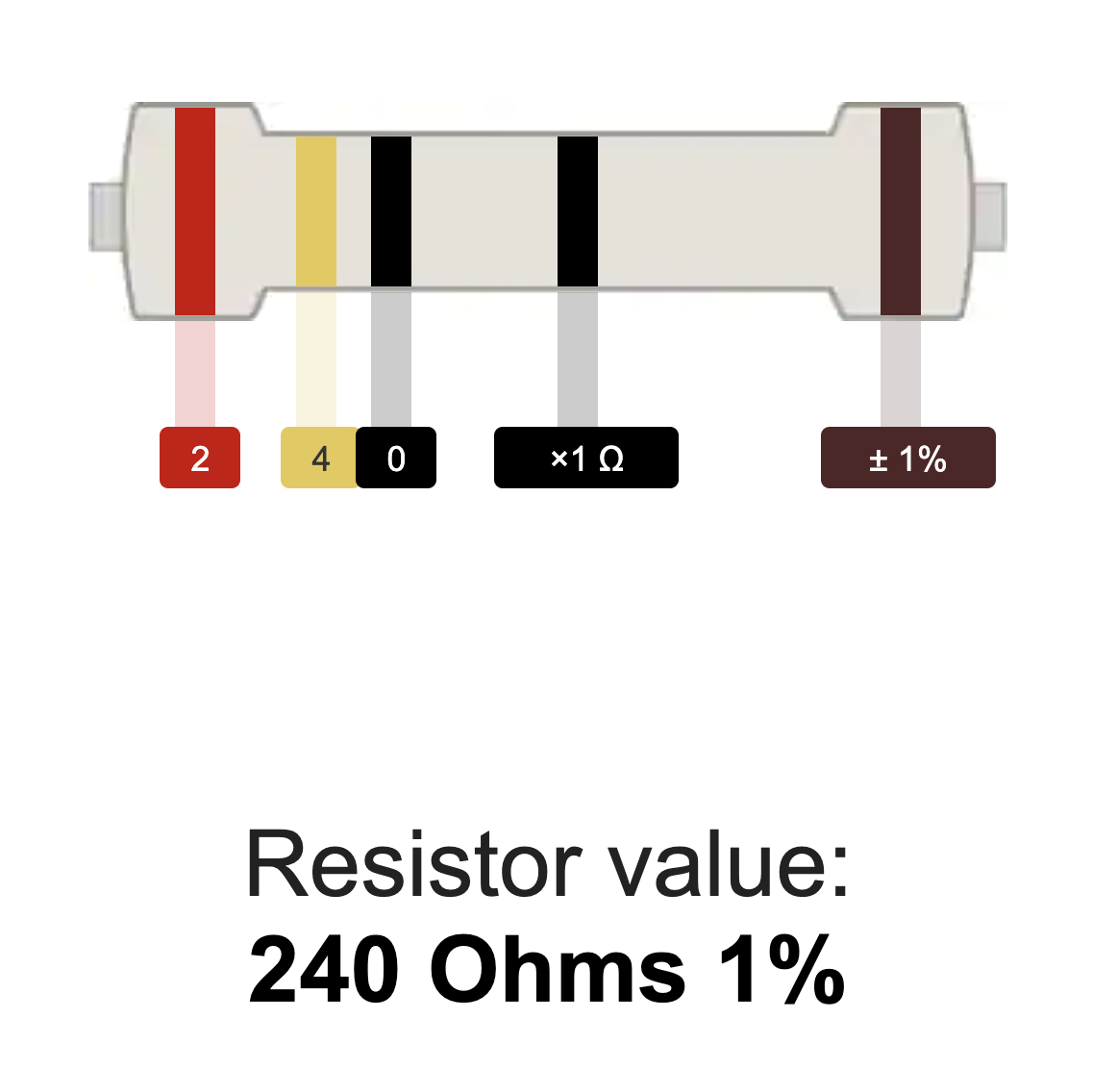 | 240Ω Resistor | R1 | 1 |
 | 330Ω Resistor | R3 | 1 |
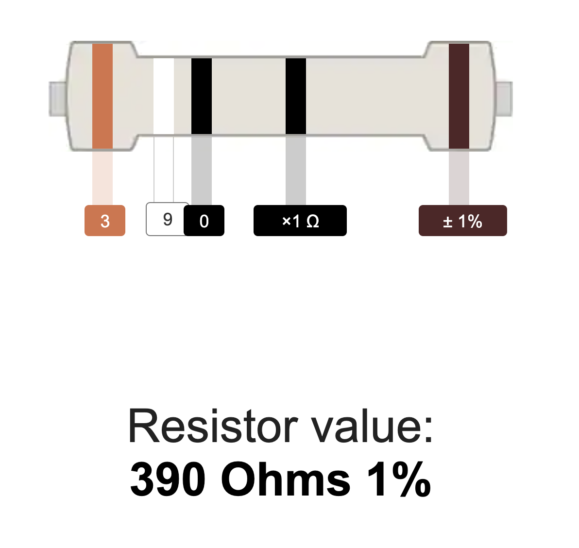 | 390Ω Resistor | R2 | 1 |
 | 4.7kΩ Resistor | R4 | 1 |
 Reads: “0.22µF” | 220nf Polarized Capacitor | C1 | 1 |
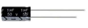
Reads: “1µF” | 1uf Polarized Capacitor | C2 | 1 |
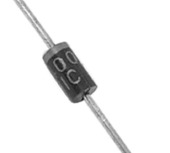
| 1N4000 Diode | D1, D2 | 2 |
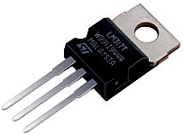
| LM317MB | U1 | 1 |
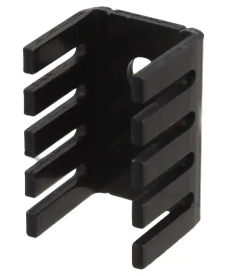 | Heatsink | M1 | 1 |
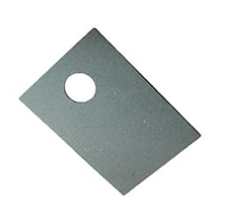 | Heatsink Pad | 1 |
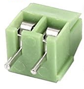
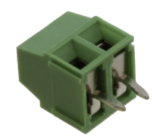 | 1x2 3.5mm Terminal Block | J3 | 1 |
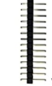 | 1x2 pin header | J2, J4, J5 | 3 |
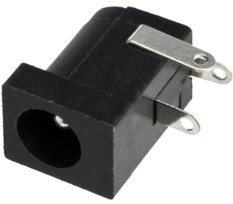 |
2.1mm Barrel Jack | J1 | 1 | |
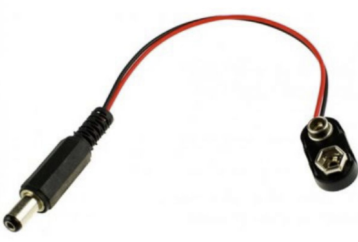 |
2.1mm Barrel Jack to 9V adapter | 1 | ||
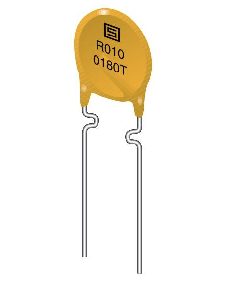 | PTC Fuse | F1 | 1 |
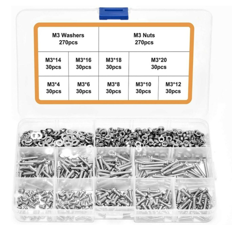 | Mounting Hardware
| 4 | |
 | Power Supply PCB | Q-PCB-001 |
1
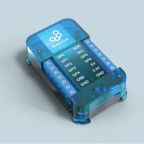
Q-Client Builder Base
1 |
Tools Used
Picture | Name | Quantity | Link |
|---|---|---|---|
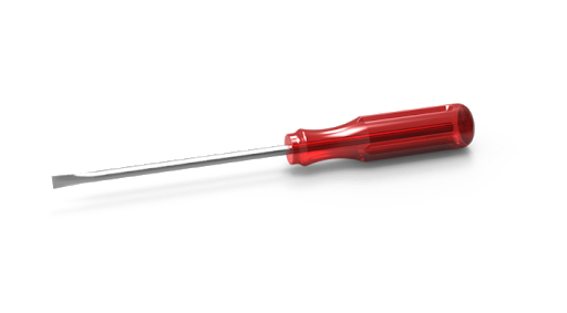 | Small slotted-head screwdriver | 1 | Included in Component Kit Or you can pick from one on our Recommended Tools List |
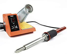 | Soldering Iron | 1 | You can pick from one on our Recommended Tools List |
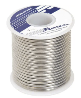 | Solder | 1 | You can pick from one on our Recommended Tools List |
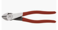 | Diagonal Cutters | 1 | You can pick from one on our Recommended Tools List |
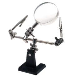 | Work Holder | You can pick from one on our Recommended Tools List |
Story
The Idea
The Power Supply kit is a handy device that can be used in a multitude of projects. You can use it to wirelessly power your builder base and all connected components. The power supply accepts 7-12V batteries via a 2.1mm barrel jack and regulates the voltage down to 5V or 3.3V. The power supply can connect to the Builder Base via the 3.3V or 5V ports.Video
| Widget Connector | ||||||||||
|---|---|---|---|---|---|---|---|---|---|---|
|
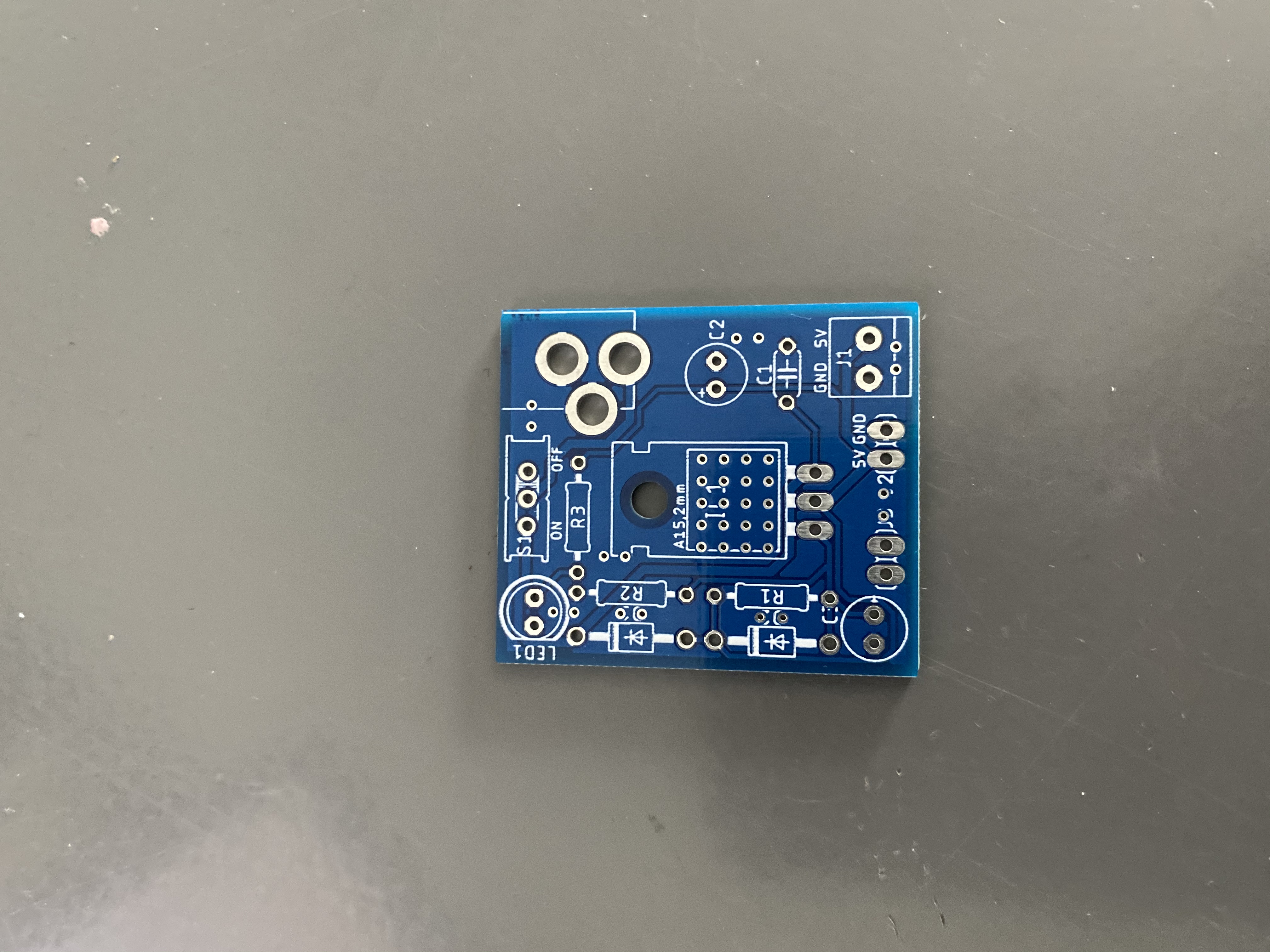
Build Process
Step 1:PCB Assembly and Soldering
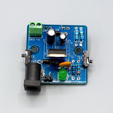
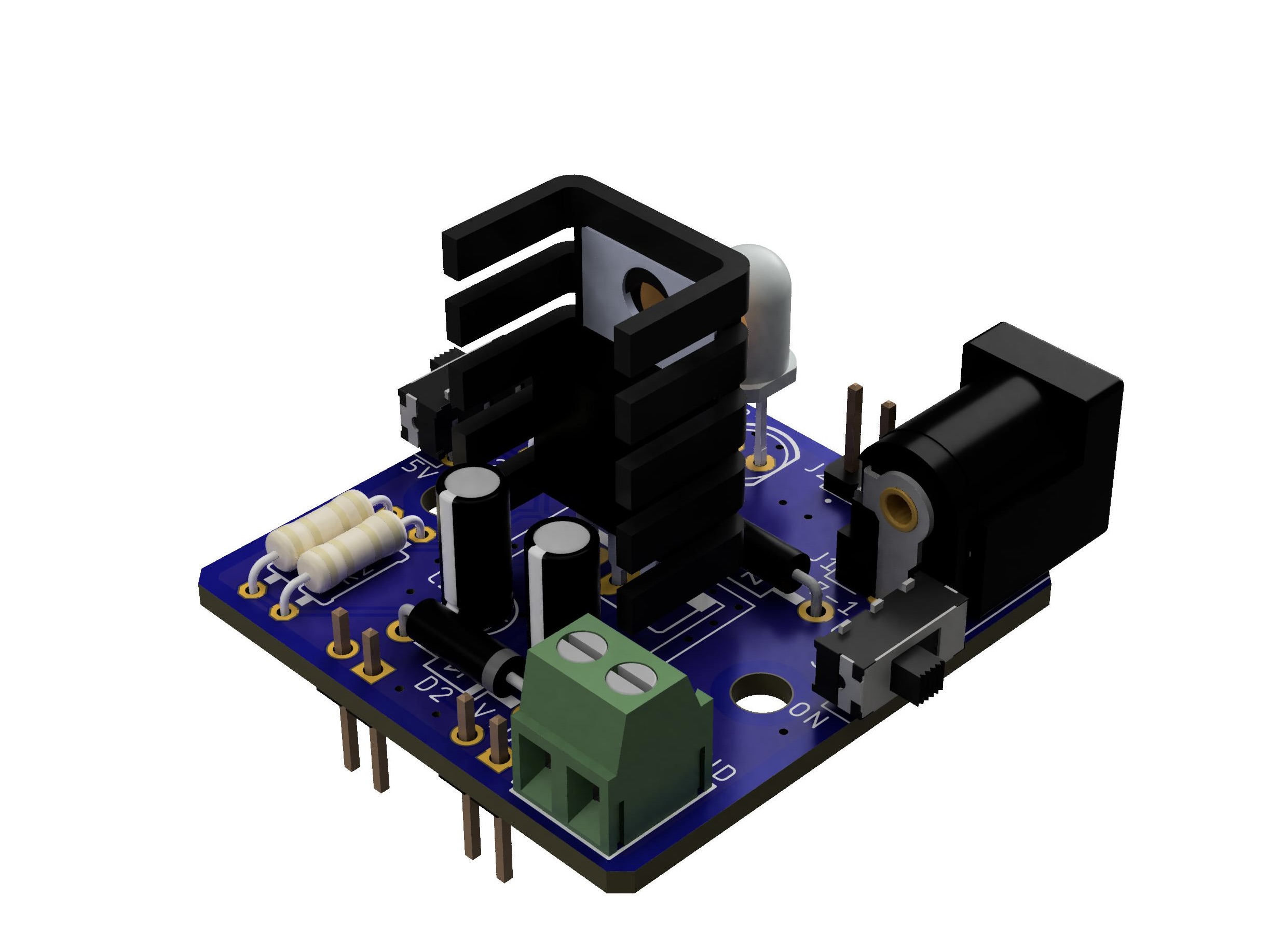
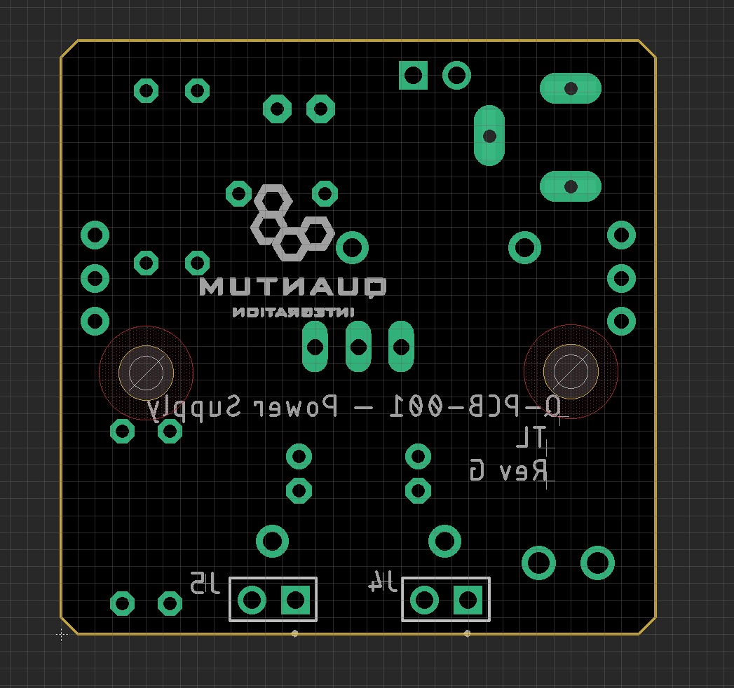
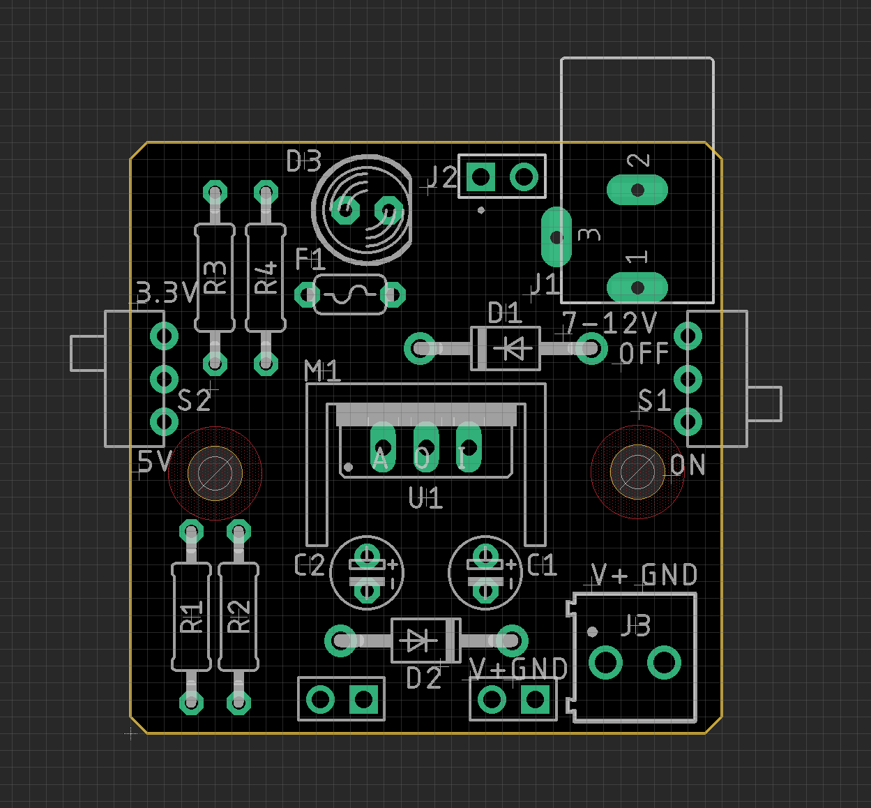
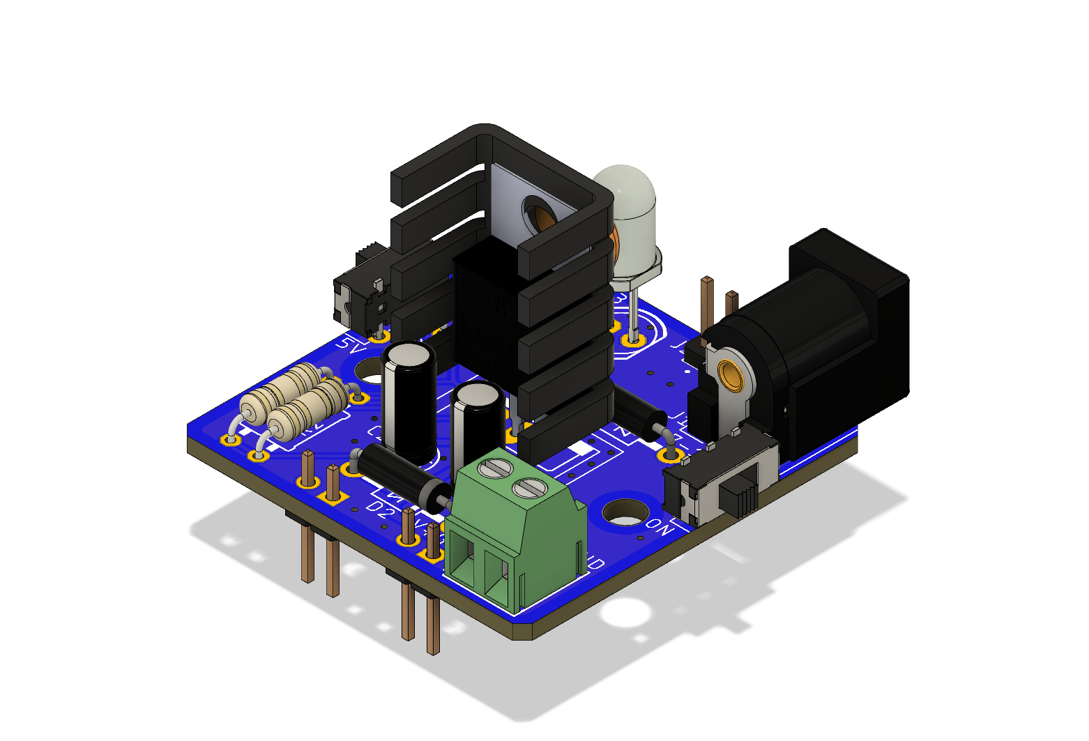
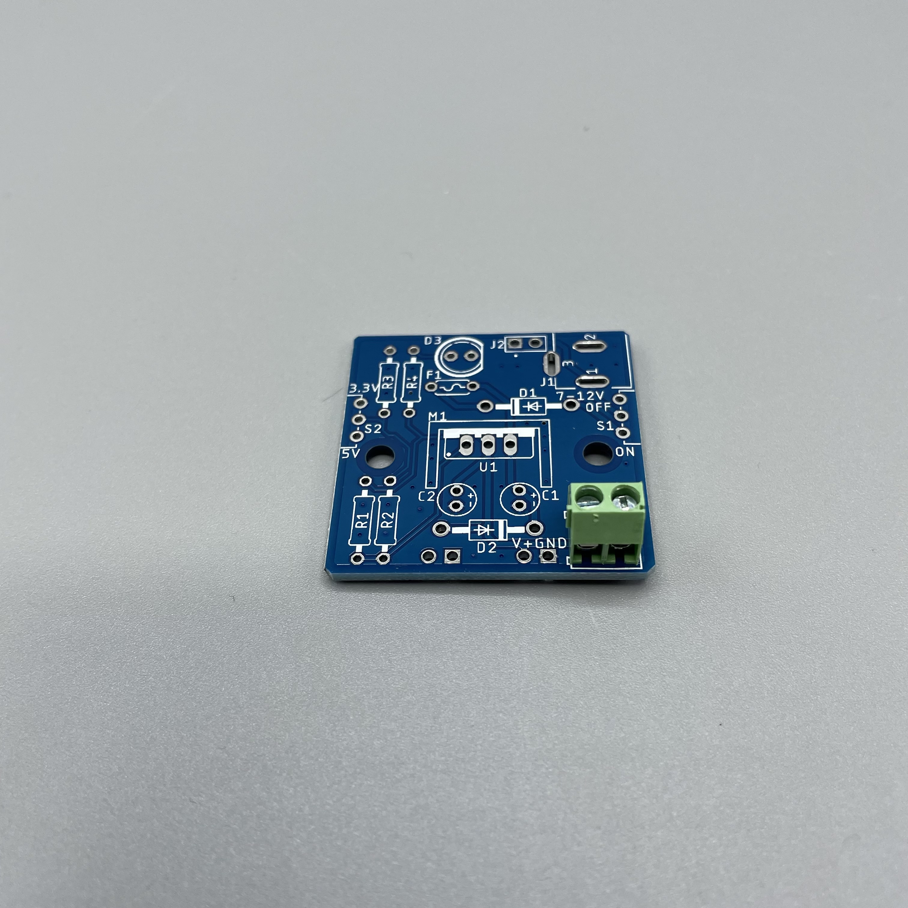
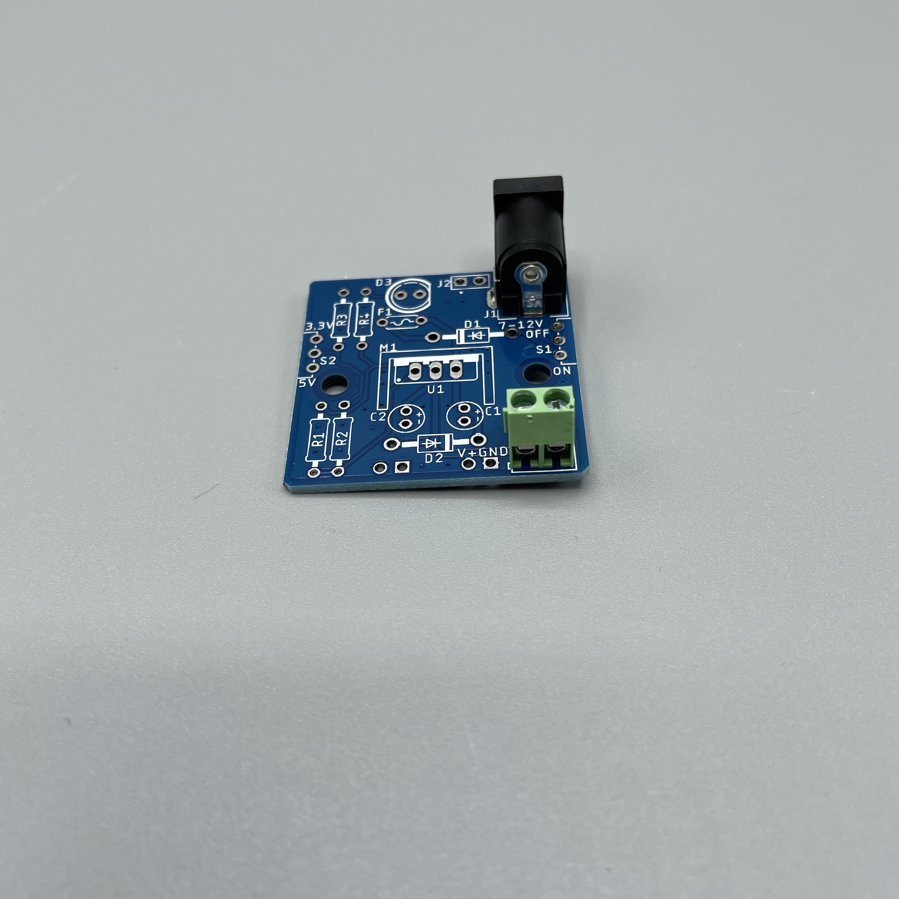
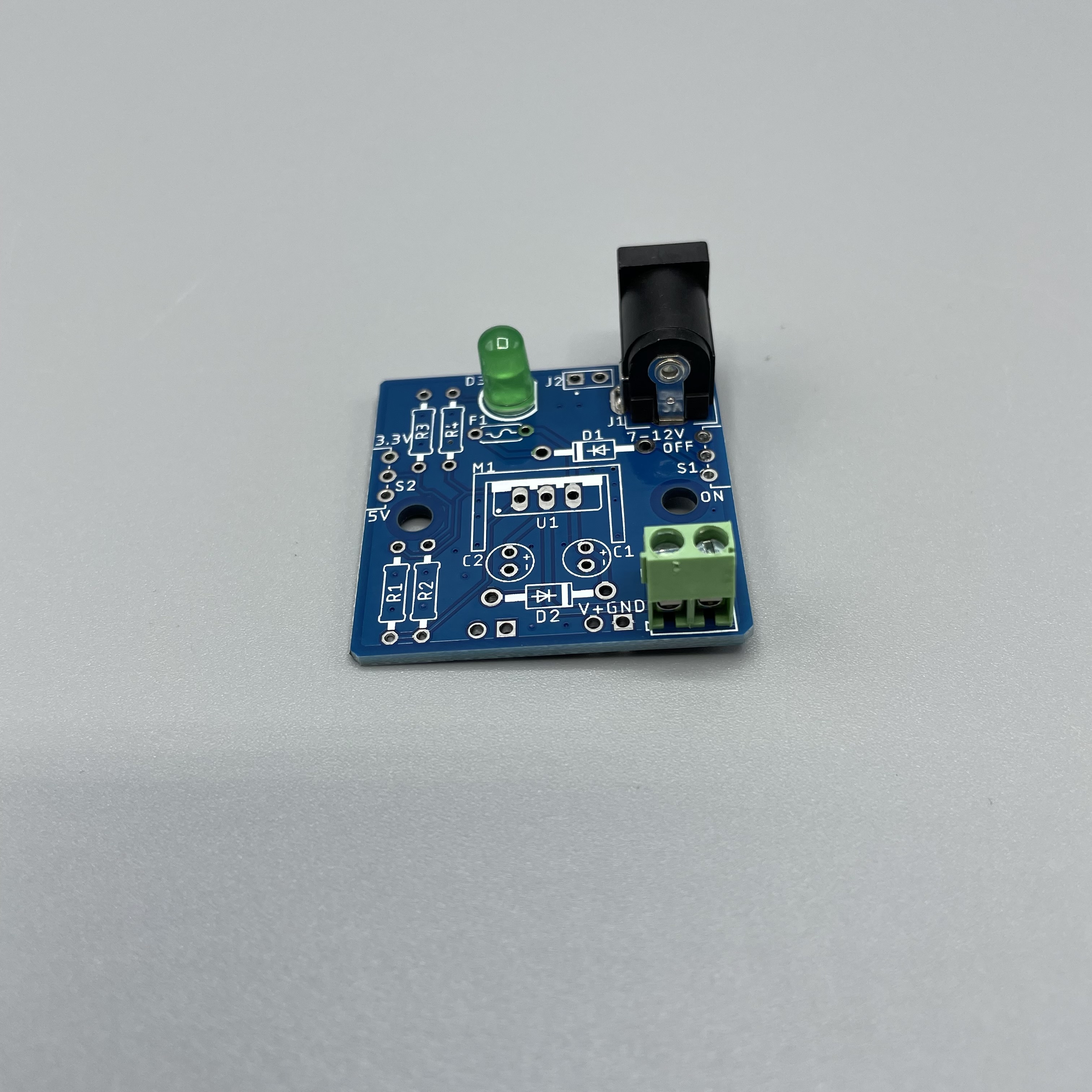
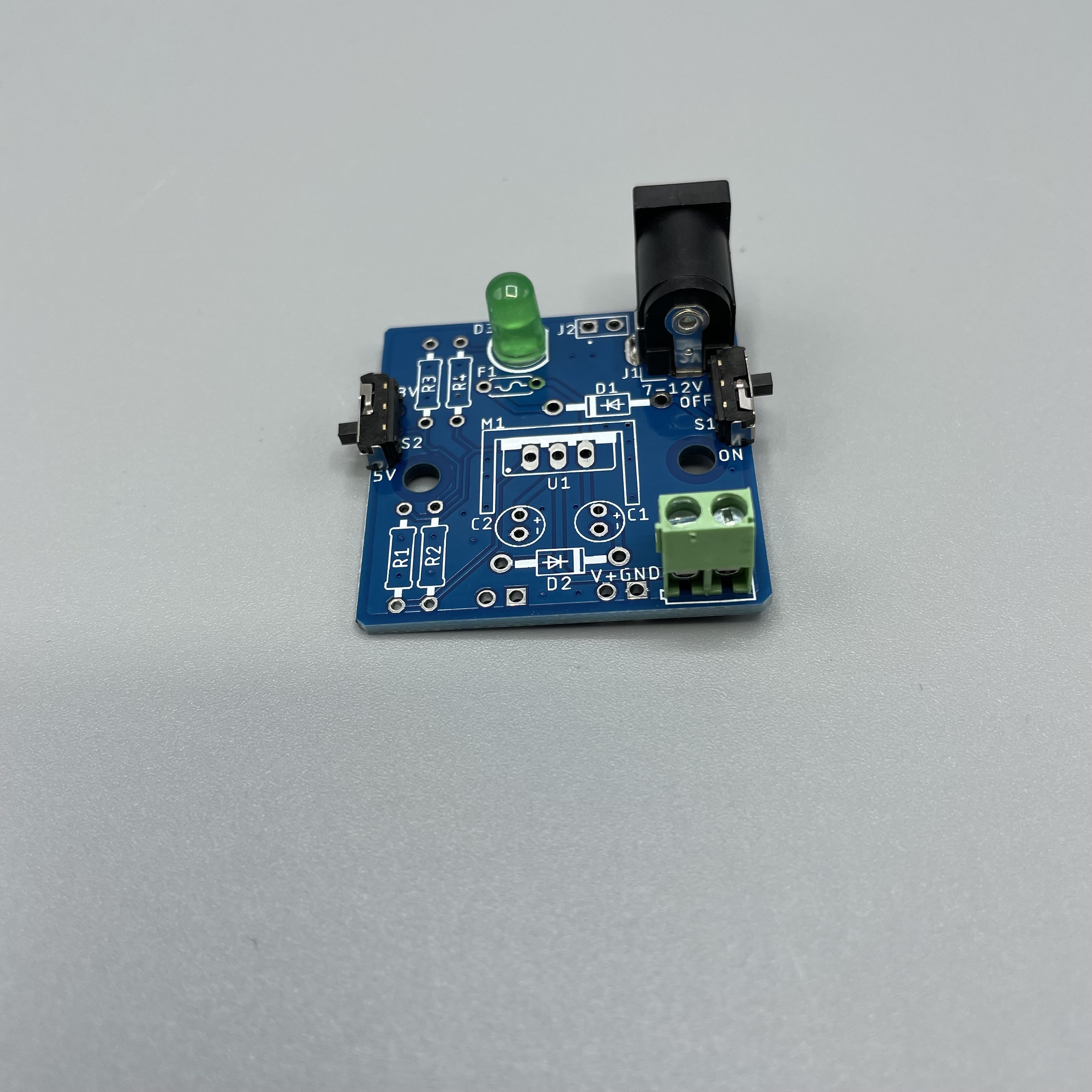
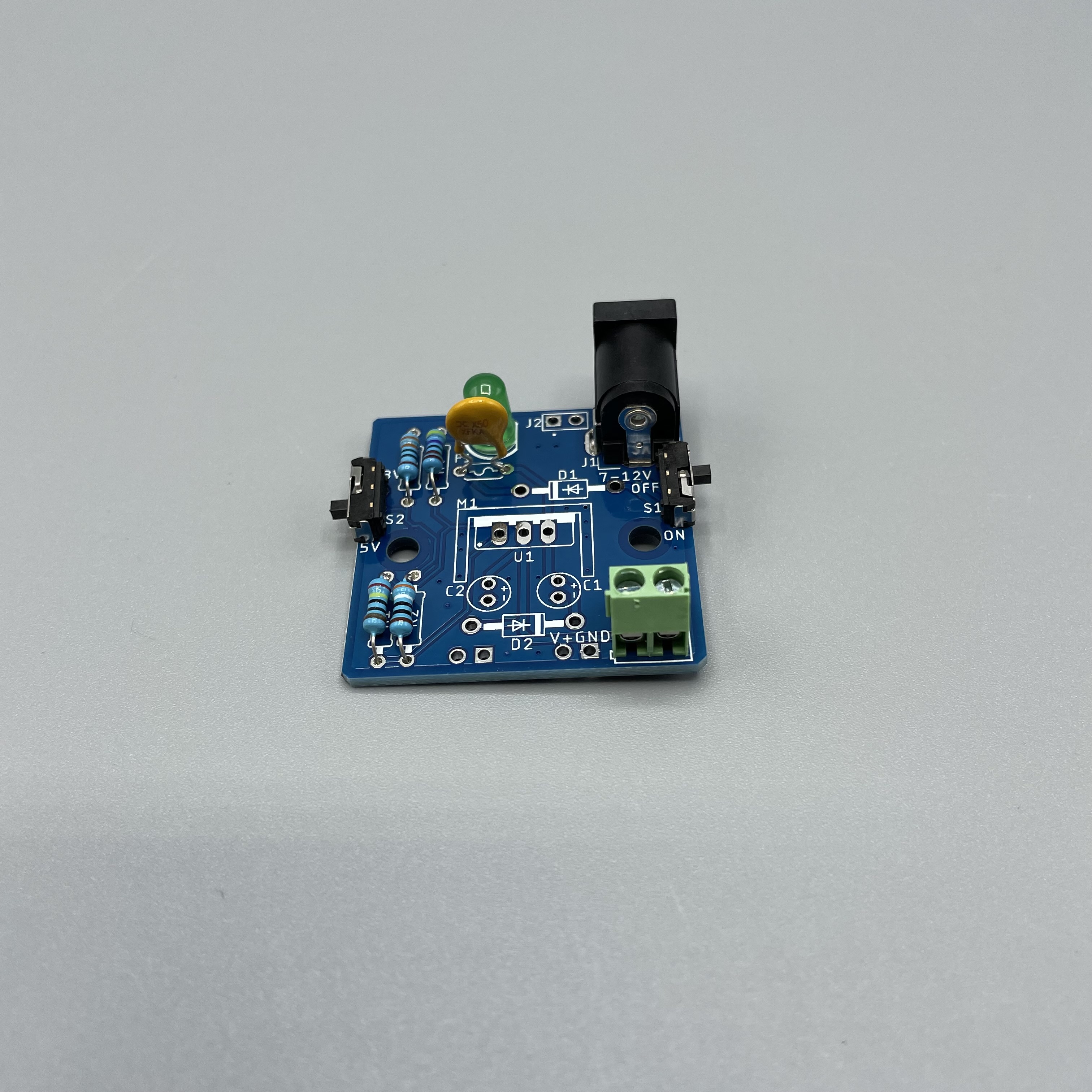
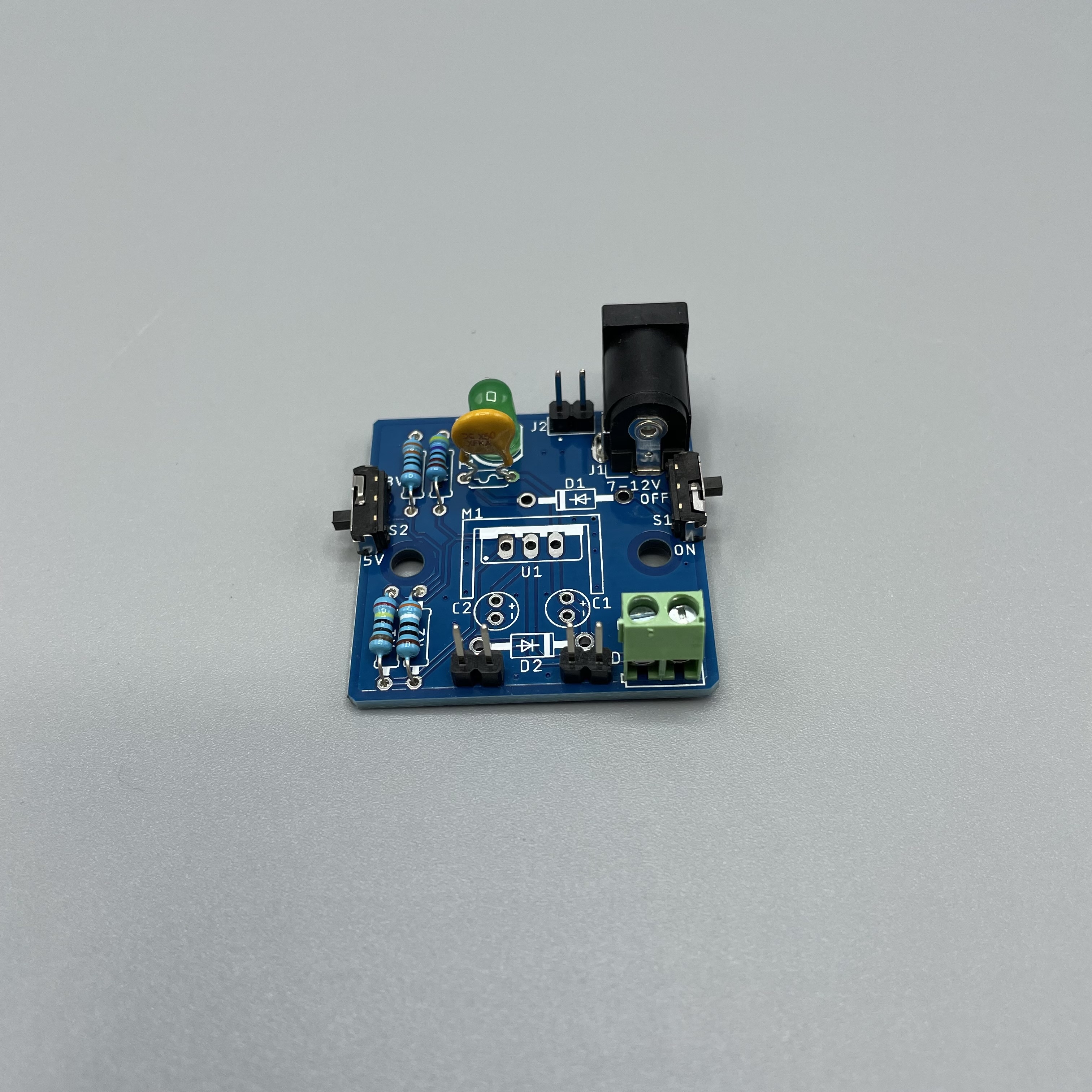
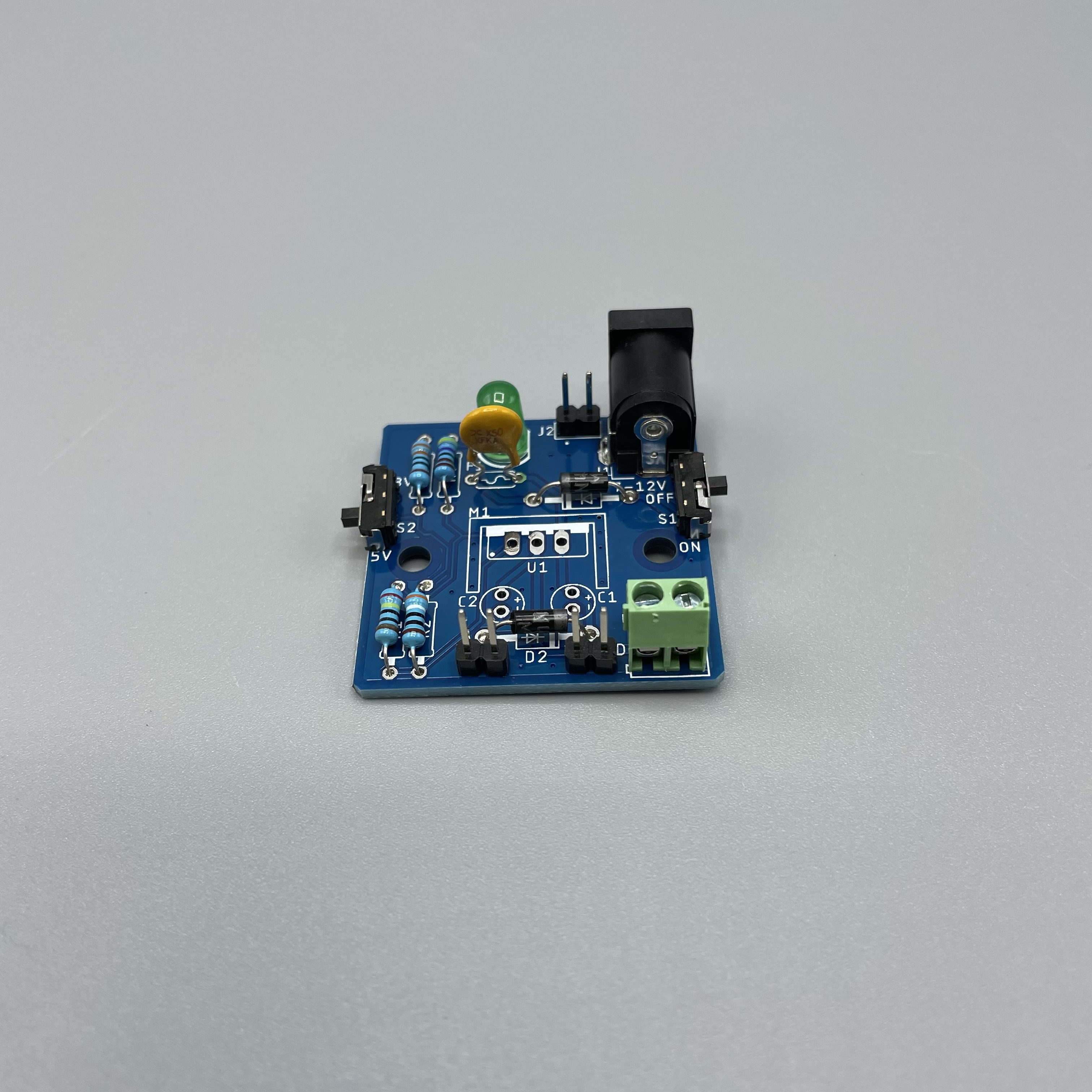
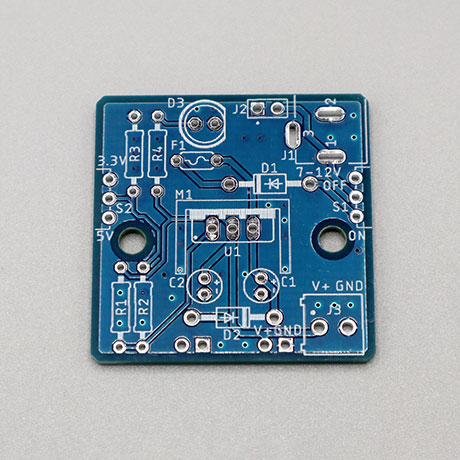
Take a look at the required components above and determine their final position on the PCB. The following images should be a good reference:
Place groups of components on the board and then solder them to the pads. It is recommended to
Using some form of work holder is advised. You can find a list of suitable work holders on our Recommended Tools List.

We will start by putting all the parts on the table.

If you are not familiar with soldering you should start with components with the lowest profile, like for example resistor resistors and then move up to components like buttons with higher profile.
To determine the values of the given resistors and to place them in the correct position, please refer to a resistor color code calculator like this one:
Using some form of work holder is advised. You can find a list of suitable work holders on our Recommended Tools List.
First we will start by soldering the terminal block.
Next solder the barrel jack. Make sure it is locking away from the board!
Solder the LED. Be sure to place the flat side of LED on the flat side of the mark.
Solder the switches. One switch will be used to change between 5V and 3.3V output and the other one will be used to turn the system on and off. Make sure the switches look away from the board. The labeling wether the switch is on or off is printed on the PCB.
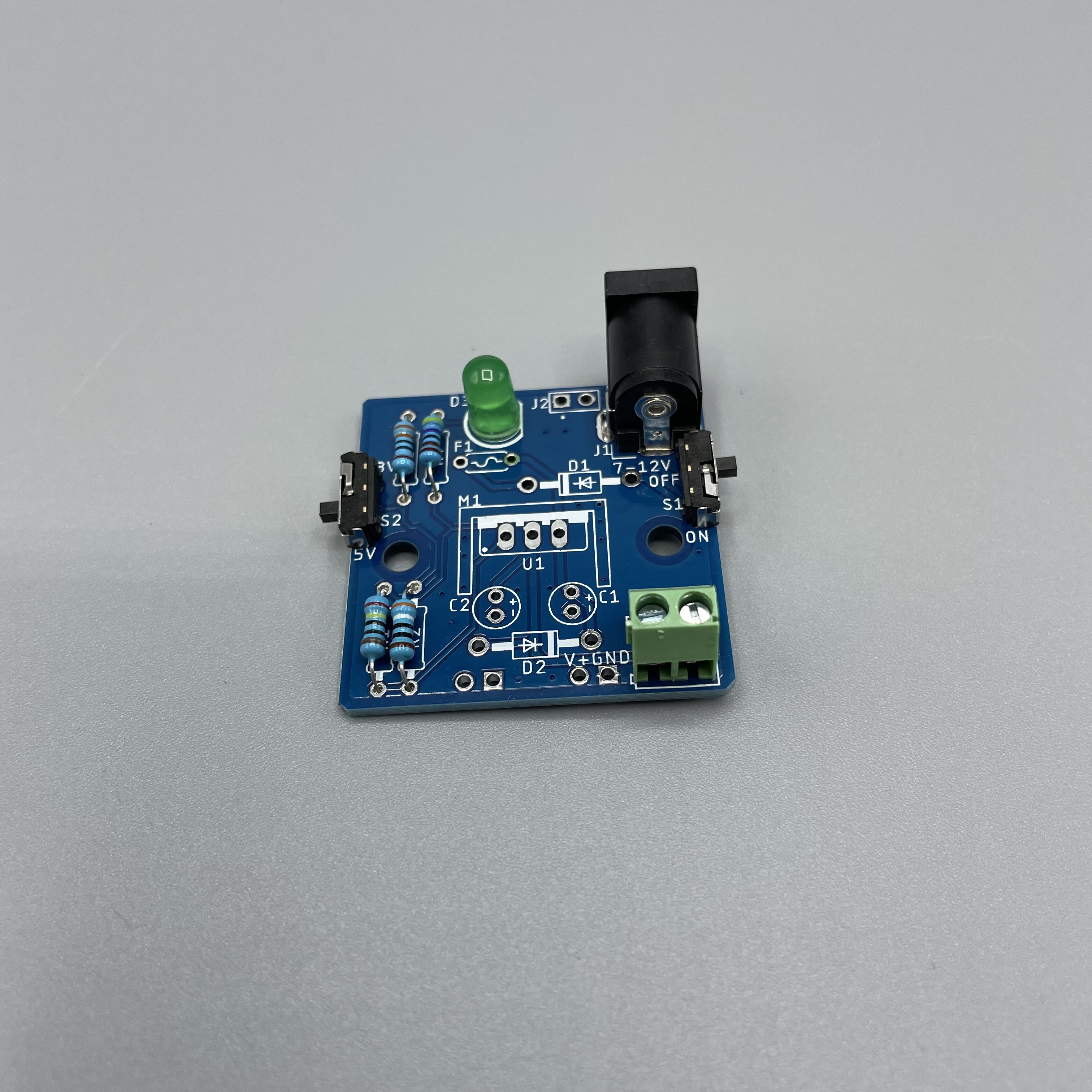
Solder the resistors. Use the pictures in the table as a reference for the colors.
R1 : 240 Ohm
R2 : 390 Ohm
R3 : 330 Ohm
R4 : 4.7k Ohm
 | 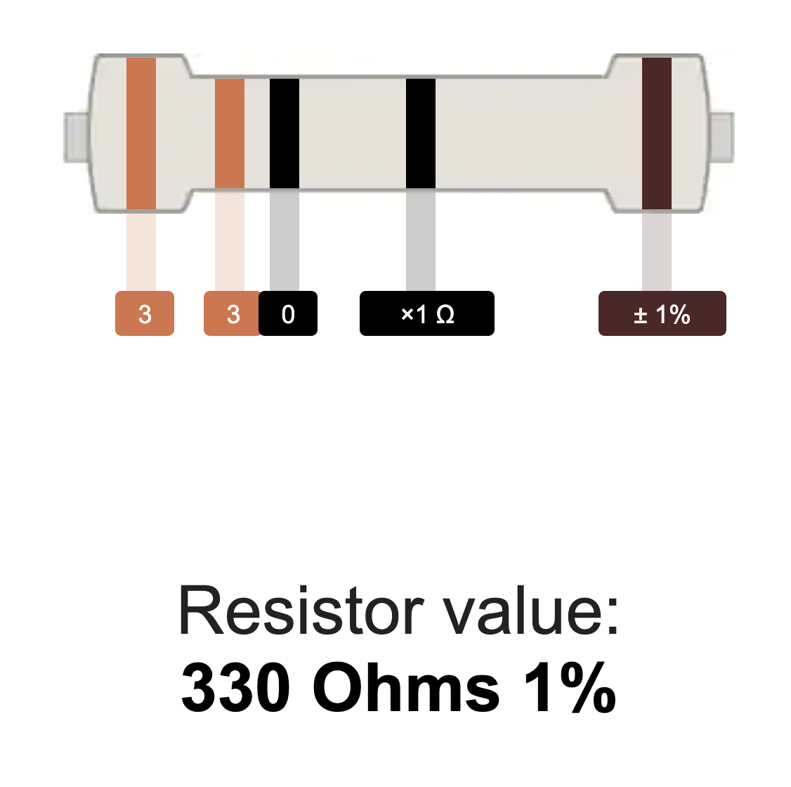 |  | 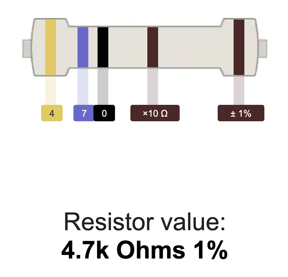 |
Solder the fuse. It's labeled with F1.
Solder the pin headers.
Solder the diodes on D1 and D2. They are both the same.
Solder the capacitors.
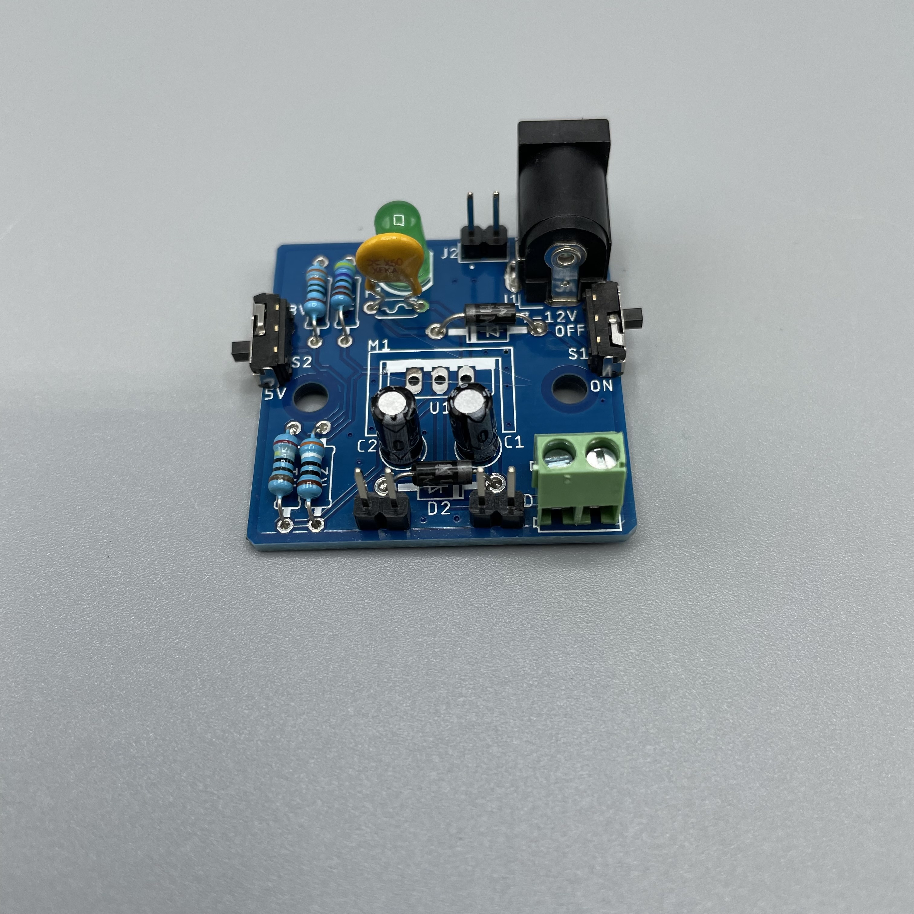
Lastly solder the LM317MB in the middle of the board and attach the heatsink as well as the heatsink pad. Don’t forget to place the heatsink pad between the heatsink (M1) and the voltage regulator (U1). Screw them together with an a M3 screw and an M3 nut that come in comes with the DIY Kit.
Two additional M3 screws are included to mount the DIY Kit to any project board.
Step 2:Your 5V Power Supply DIY Kit is now ready to be used!
Connecting to the Builder Base
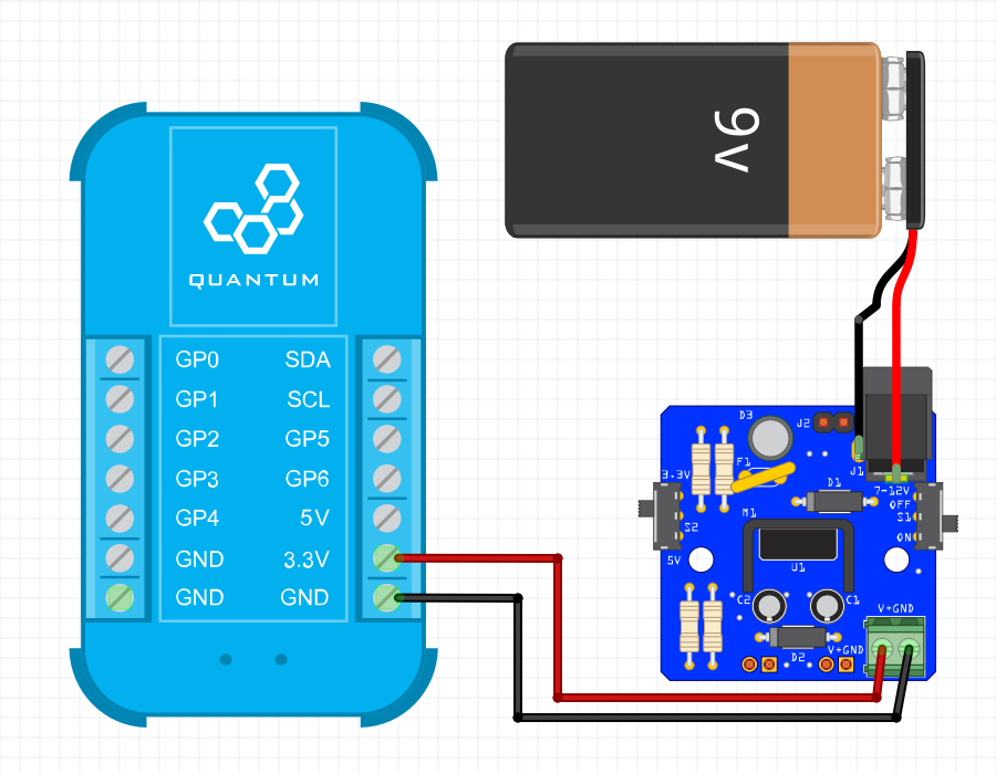
You have two options for connecting the power supply to your Builder Base: you can use the male headers on the bottom of your PCB to stick it on the GND and VCC rails of a bread board, or you can use the screw terminals located on the top of your power supply. Both options serve the same purpose, but one might work better for a given project than the other. Don’t forget to set the switch to your desired voltageIf you are using the image above as a reference make sure to have the switch in the 3.3V position. If you want to change to 5V also change the wires to the 5V Terminal at the Builder Base. You know that your DIY Kit is powered and ready to be used when the LED lights up.
Projects
Any project compatible
The Power Supply DIY Kit can be used in a variety of projects! It can power your Builder Base or your entire Breadboard circuit!

Gallery


Resources
This DIY Kit page is currently optimized for revision G.
Current revision
Assembly files for the current revision of the DIY Kit (Rev G): | https://github.com/QuantumIntegration/Q-PCB-001-Power-Supply-Hardware-Files/tree/Rev_G |
|---|
Older revisions
- | - |
|---|