| Table of Contents |
|---|
Overview
| Widget Connector | ||||||||||
|---|---|---|---|---|---|---|---|---|---|---|
|
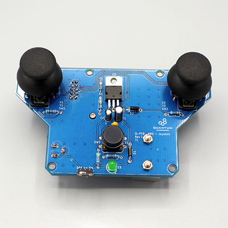
The Joystick DIY Kit allows one to control numerous projects with the Quantum Platform, like a remote controlled car or a robotic arm. This The motivation behind creating the Joystick DIY Kit page is currently optimized for revision Iis to offer a project that is simple to build and highly versatile to use. With this Joystick Kit you are able to easily control a wide variety of motorized projects. The full DIY Kit can be purchased here.
|
|---|
|
|
|---|
|
|---|
|
|---|
|
|---|
Hardware Components
The components are part of the DIY Kit or can be sourced separately with help of the BOM:
| View file | ||
|---|---|---|
|
Picture | Name | Designator | Quantity |
|---|---|---|---|
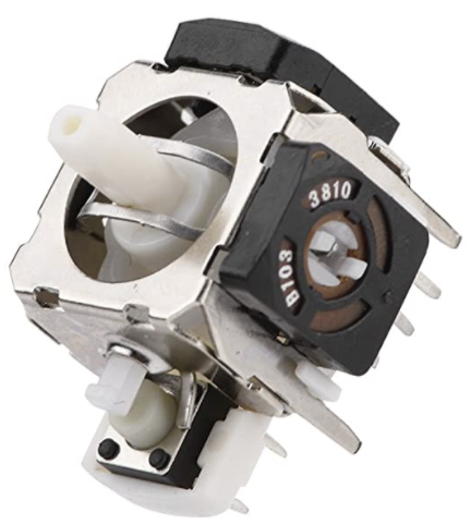 | Thumb Joystick with Cap | U1, U2 | 2 |
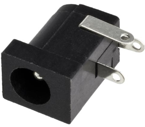 | 2.1mm Barrel Jack | J2 | 1 |
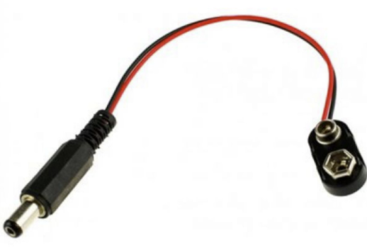 | Battery Harness | 1 | |
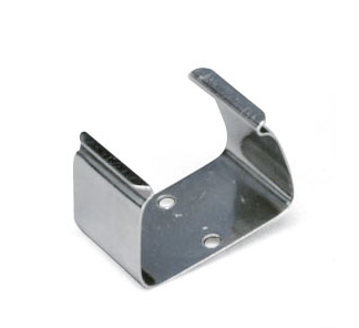 | Battery Holder | M1 | 1 |
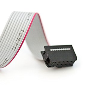
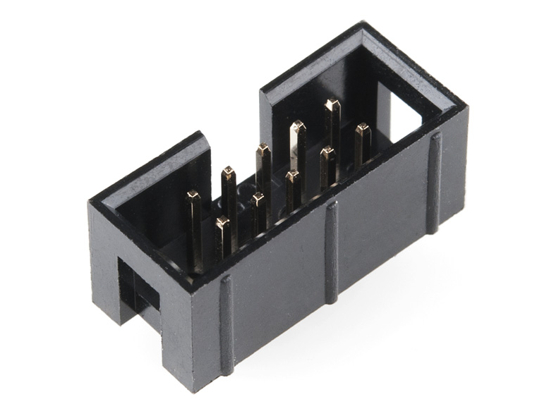 | Ribbon Connector | J1 | 1 |
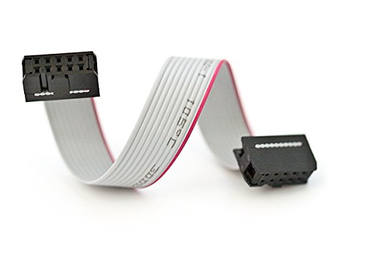 | Ribbon Cable | 1 | |
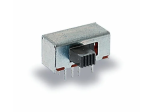 | Sliding Switch | S2 | 1 |
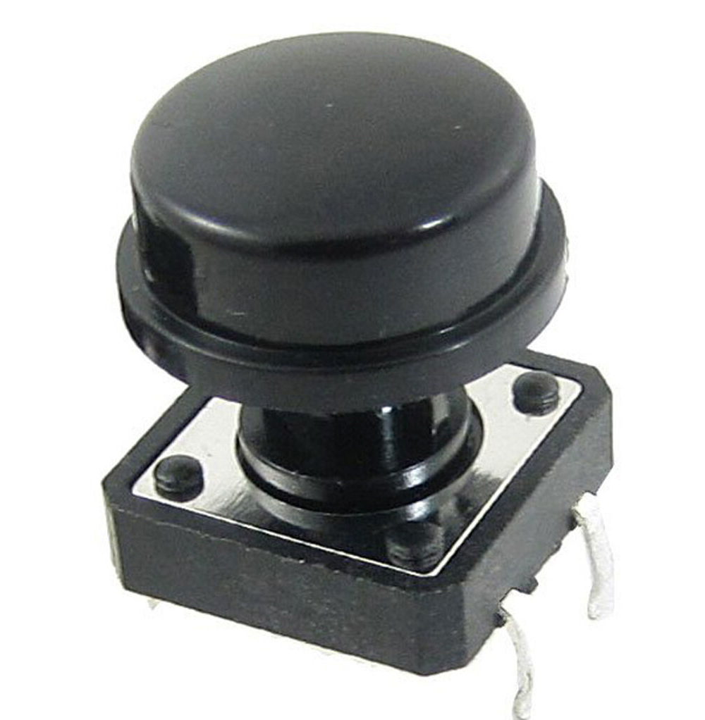 | Tactile Button | S1 | 1 |
 Reads: “0.22µF” | 220n Polarized Capacitor | C1 | 1 |
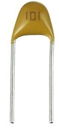 Reads: “104” | 100n Capacitor | C3 | 1 |
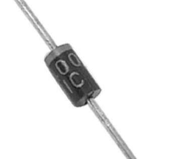 | 1N4000 Diode | D1, D2 | 2 |
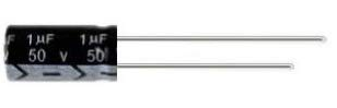
Reads: “1µF” | 1u Polarized Capacitor | C2 | 1 |
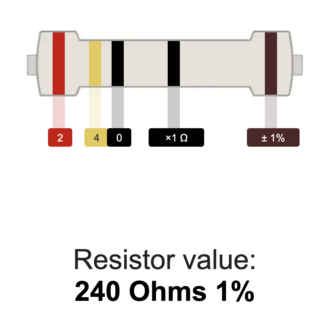
 | 240Ω Resistor | R5 | 1 |
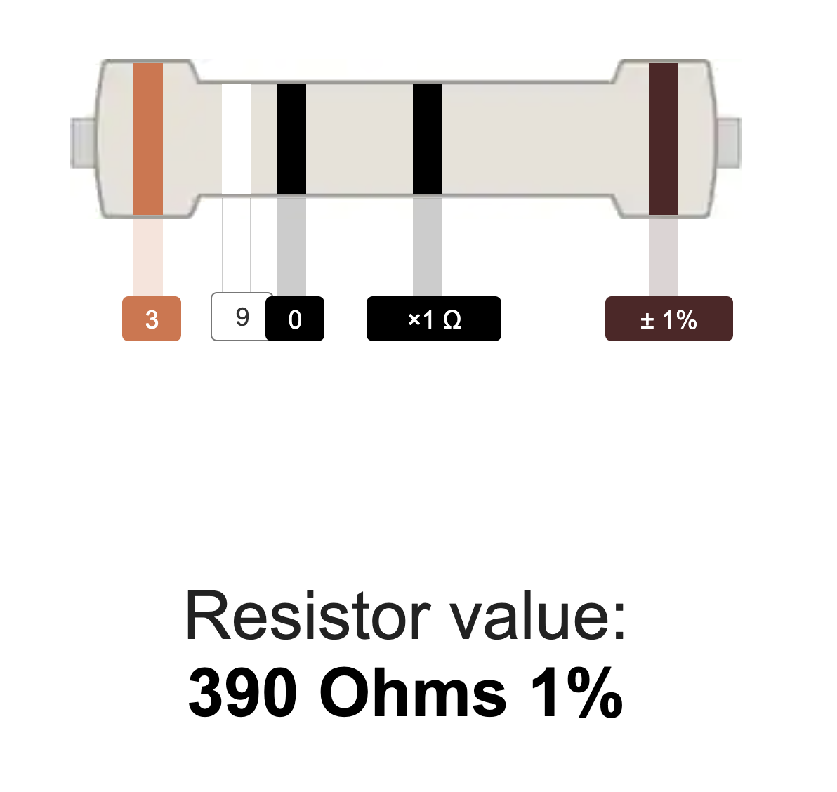 | 390Ω Resistor | R6 | 1 |
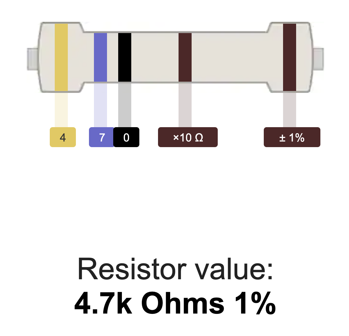 | 4.7kΩ Resistor | R2 | 1 |
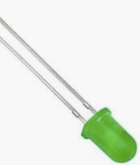 | Radial LED (5mm) | D3 | 1 |
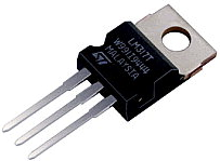 | LM317MB | U3 | 1 |
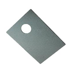 | Heatsink Pad | 1 | |
 | 10kΩ Resistor | R1, |
R3, R4 | 3 | ||
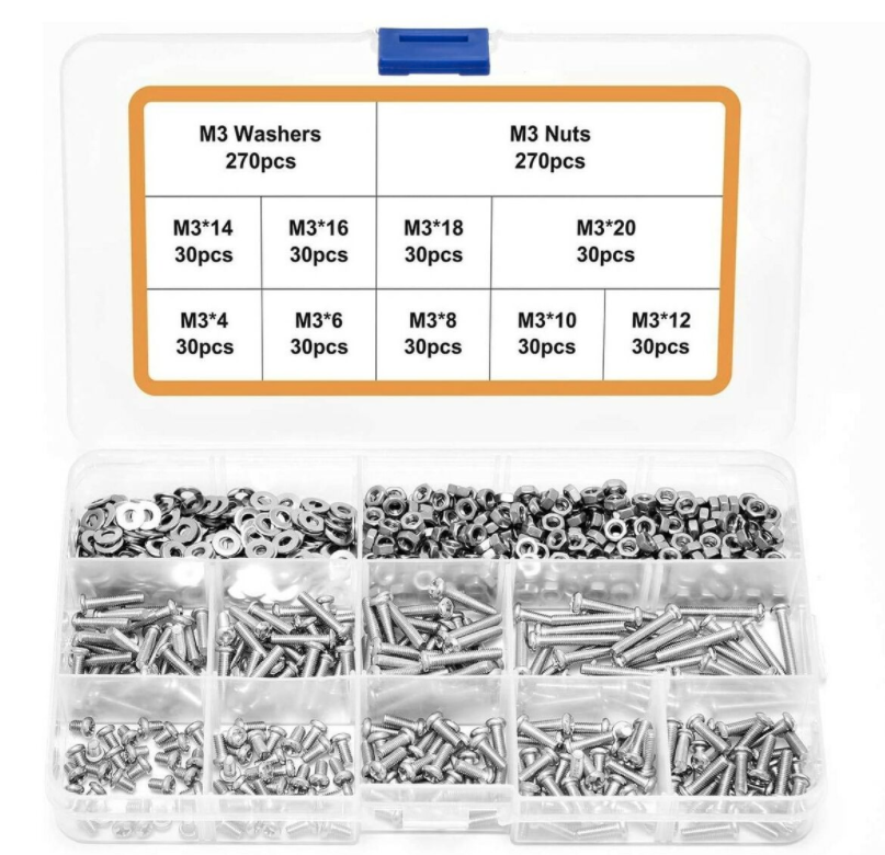 | Mounting Hardware
| 18 | |
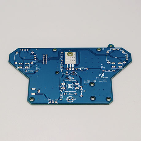
 | Joystick PCB | Q-PCB-001 | 1 |
Q-Client Builder Base
1
Tools Used
Picture | Name | Quantity | Link |
|---|---|---|---|
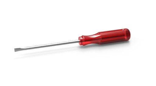 | Small slotted-head screwdriver | 1 | Included in the |
or you can pick from one on our Recommended Tools List | |||
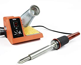 | Soldering Iron | 1 | You can pick from one on our Recommended Tools List |
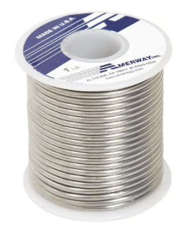 | Solder | 1 | You can pick from one on our Recommended Tools List |
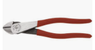 | Diagonal Cutters | 1 | You can pick from one on our Recommended Tools List |
 | Work Holder | 1 | You can pick from one on our Recommended Tools List |
Story
The idea
The motivation behind creating the Joystick DIY Kit is to offer a project that is simple to build and highly versatile to use. With this Joystick Kit you are able to easily control a wide variety of motorized projects.
Video
Build Process
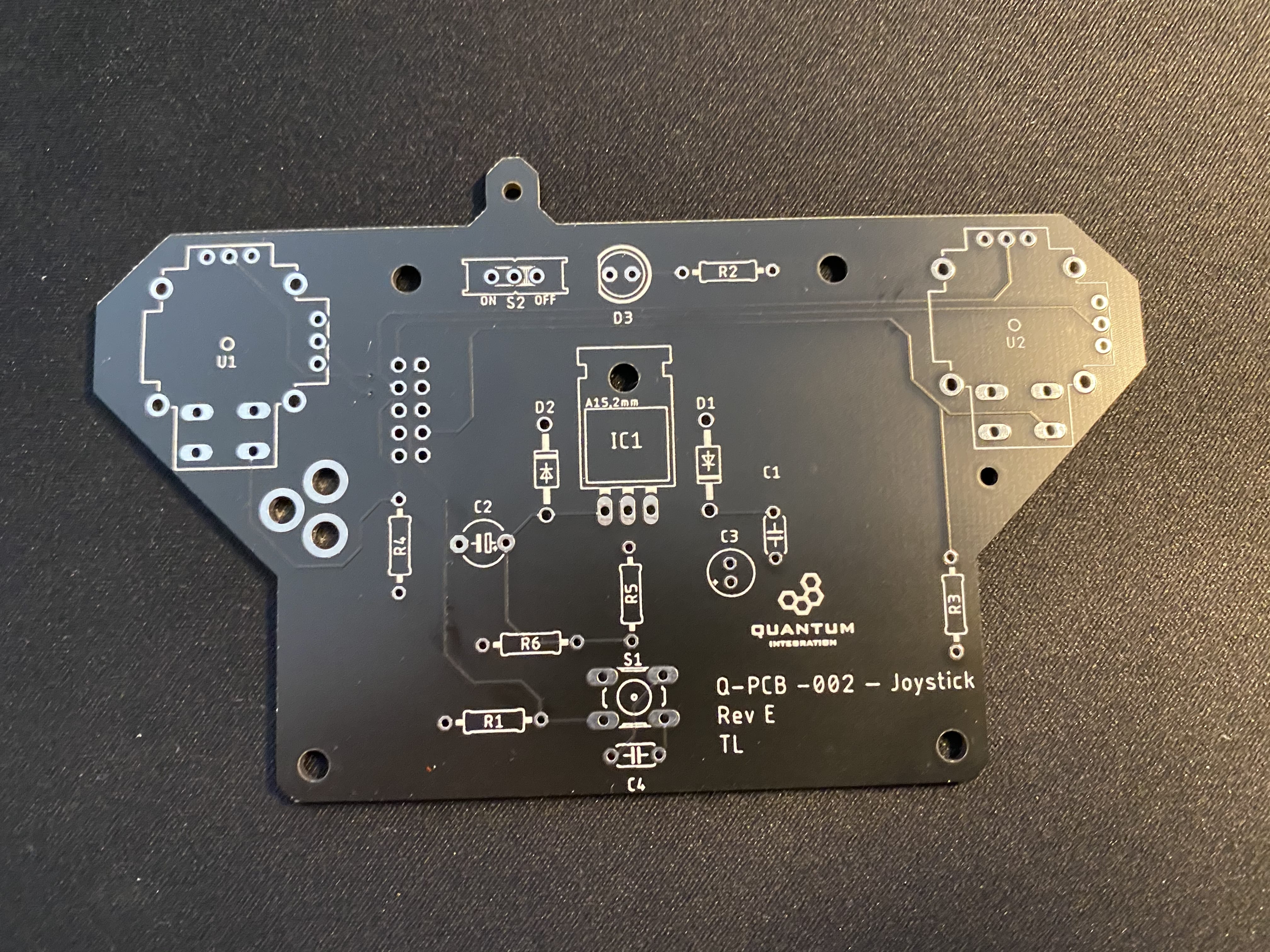
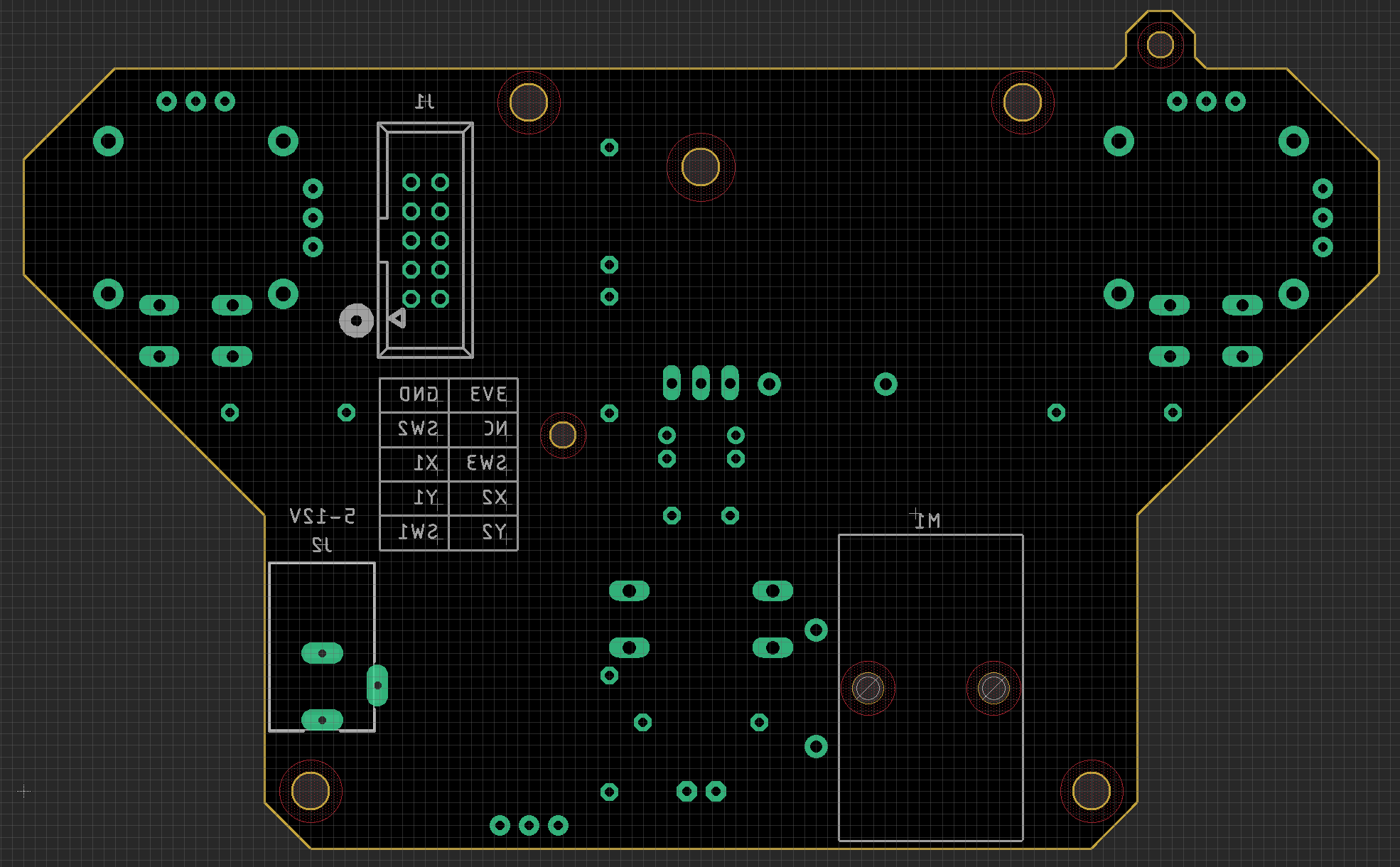
Step 1:PCD Assembly and Soldering
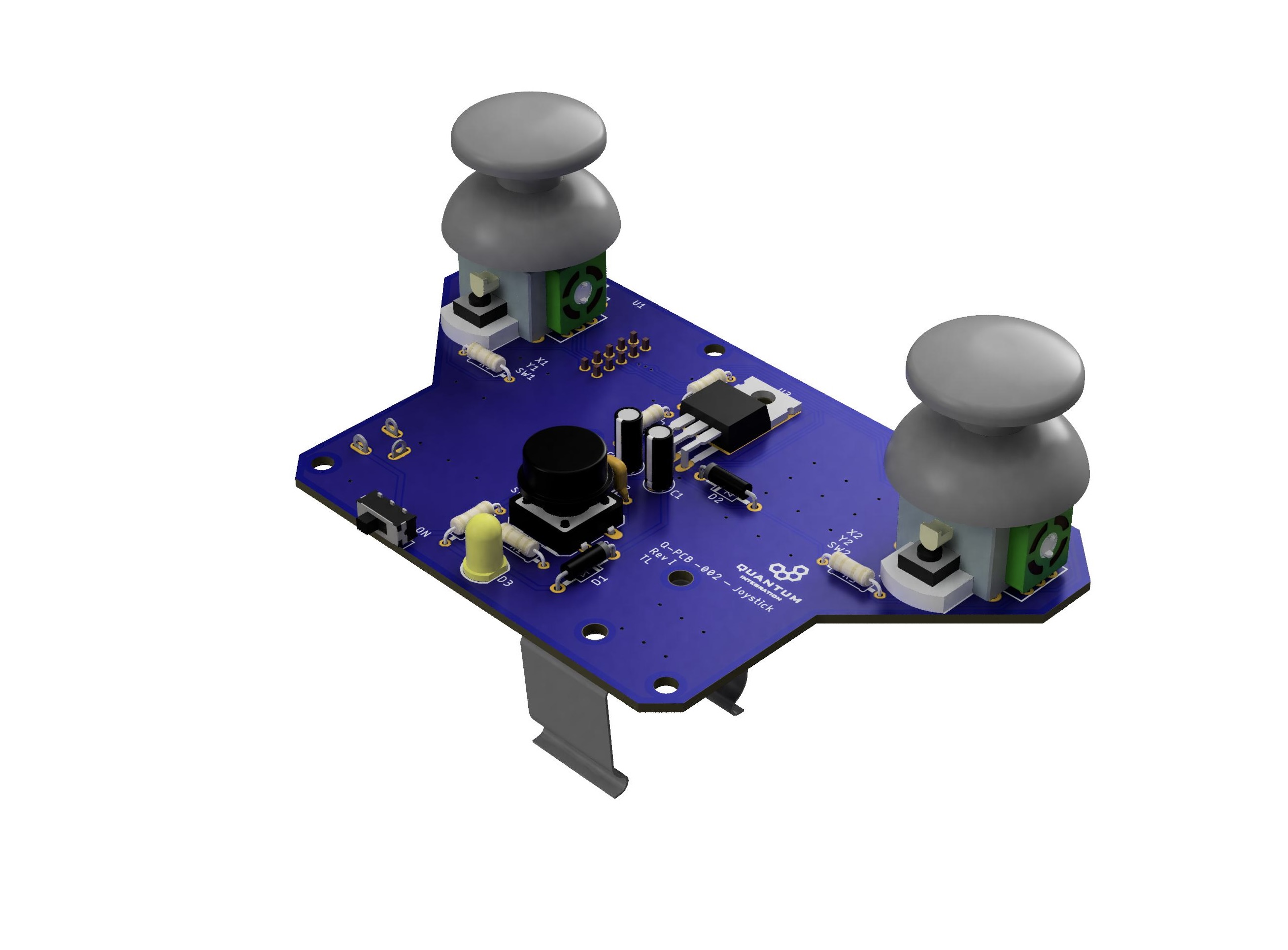
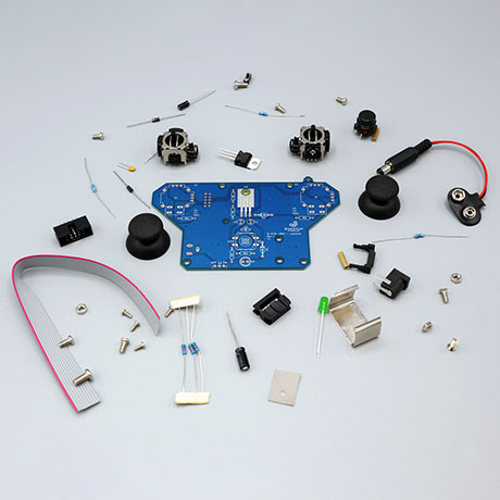
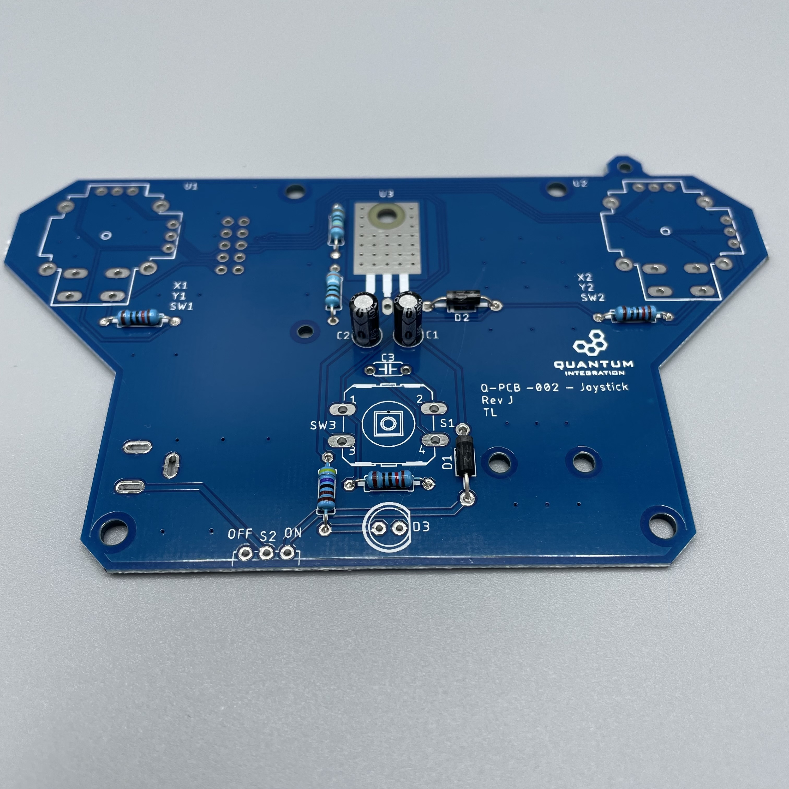
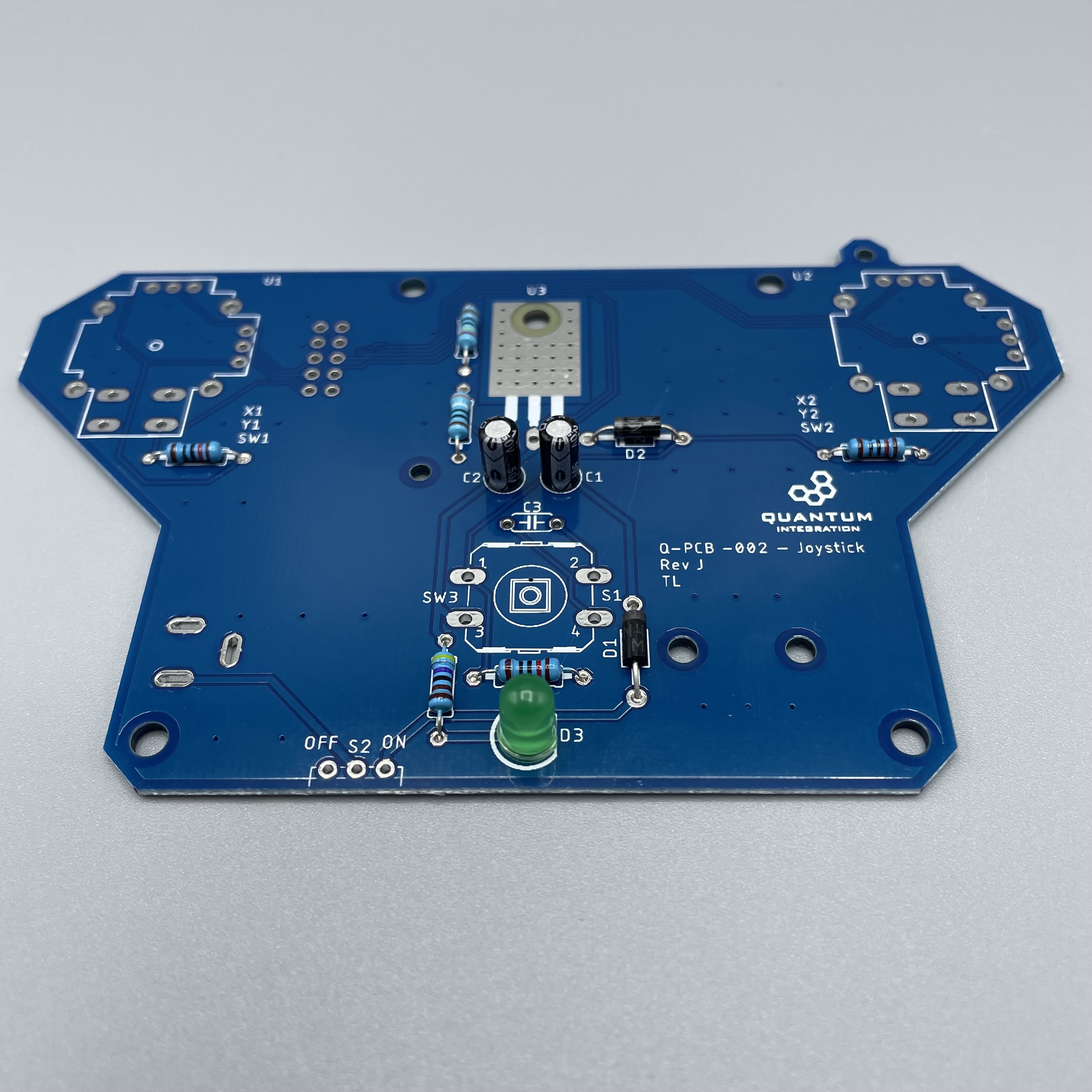
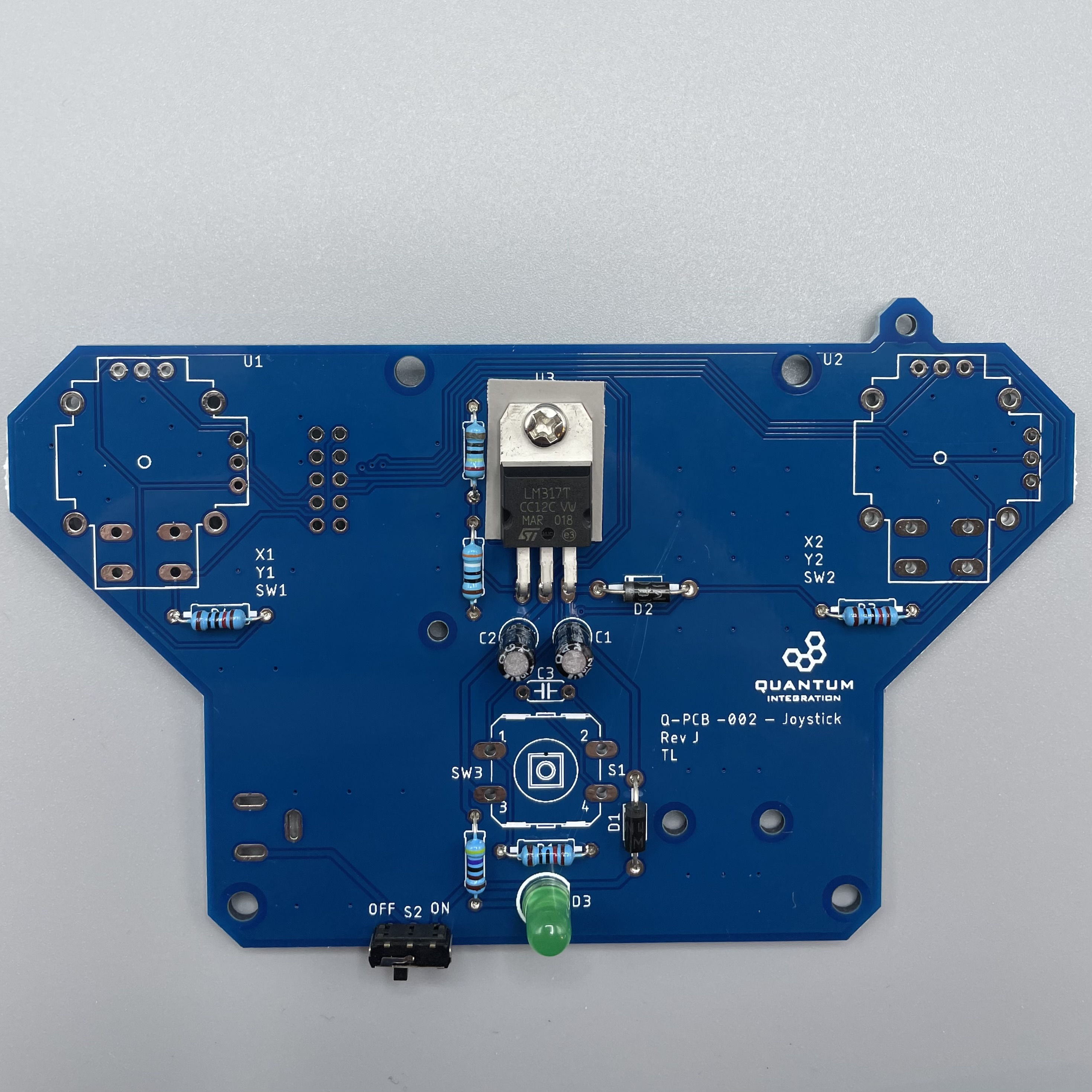
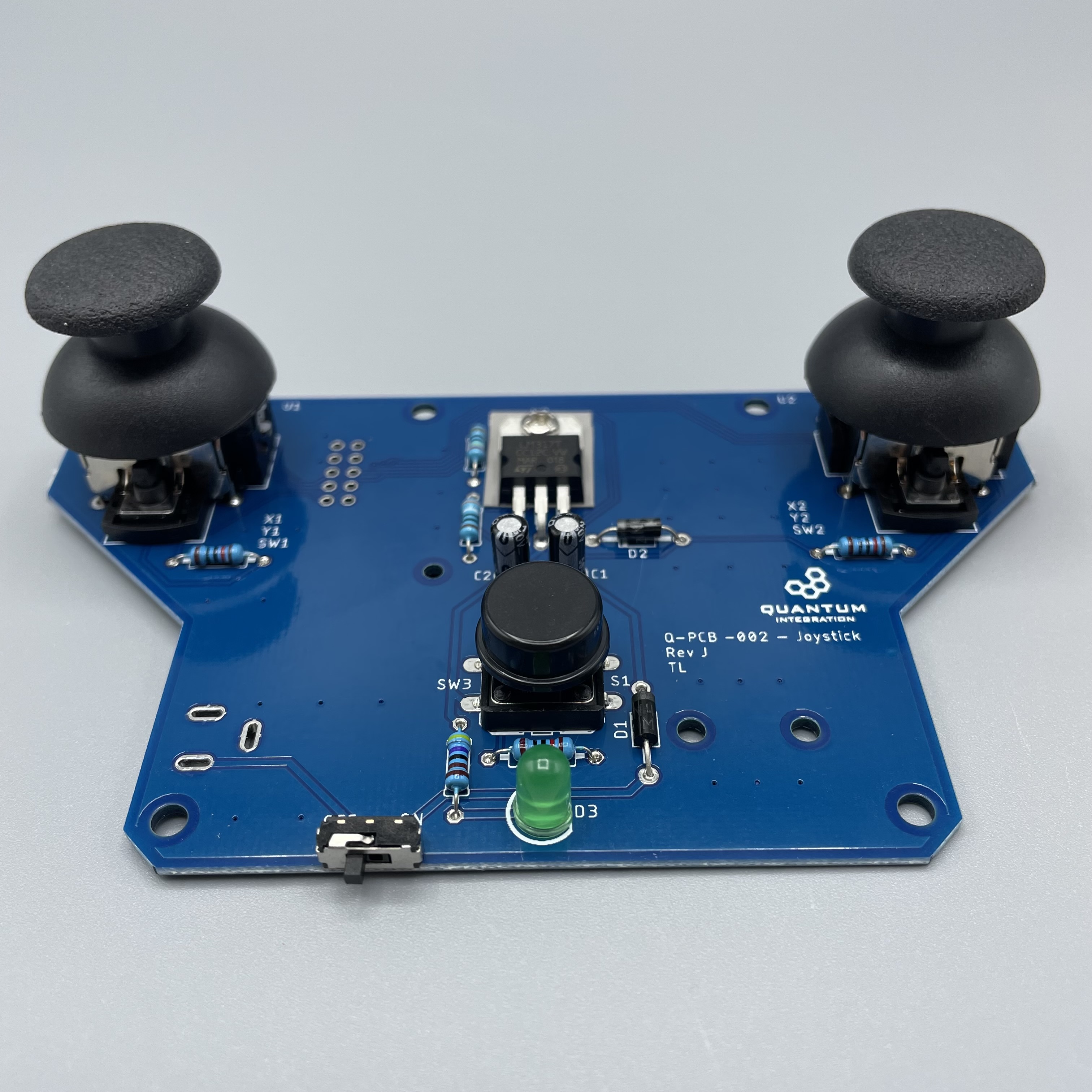
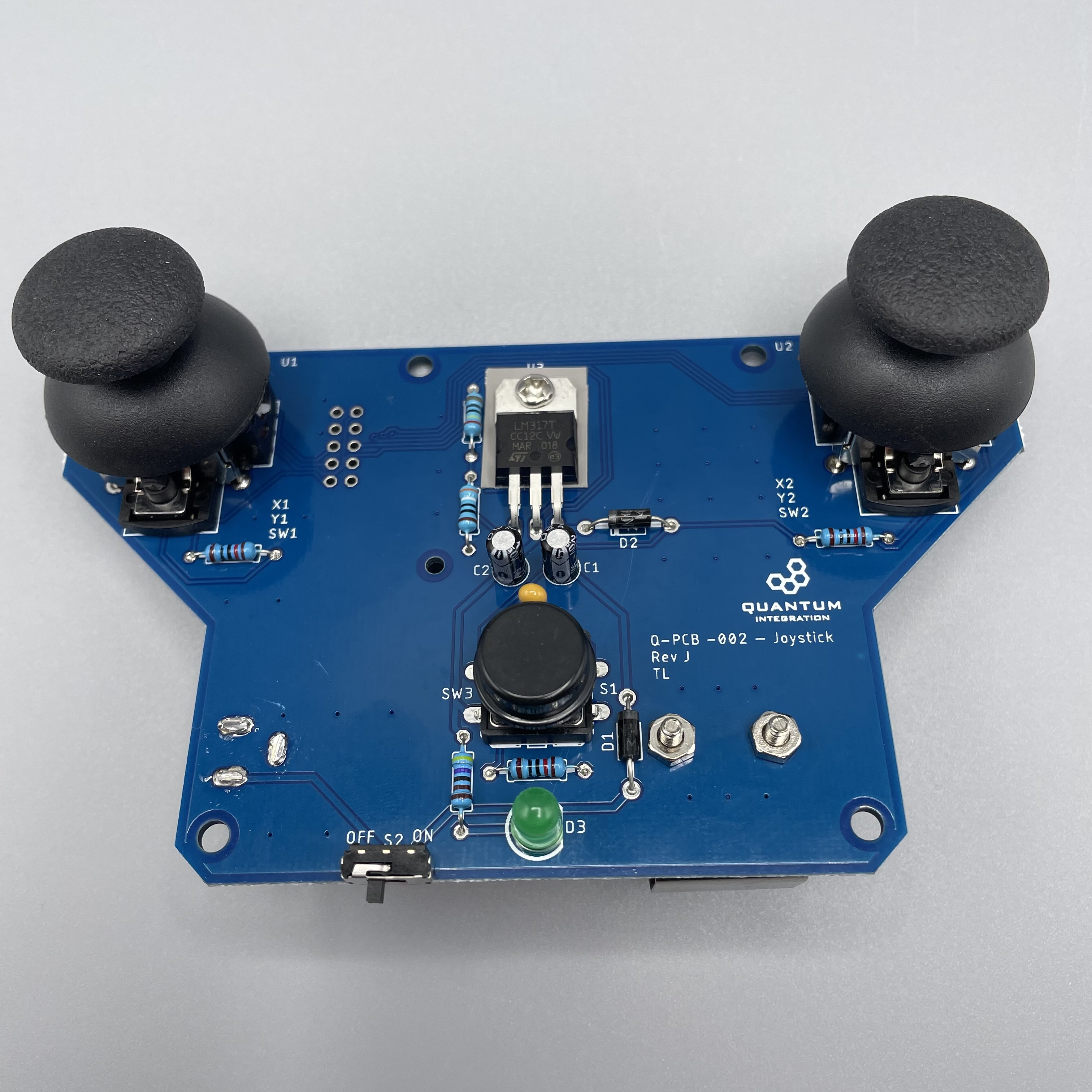
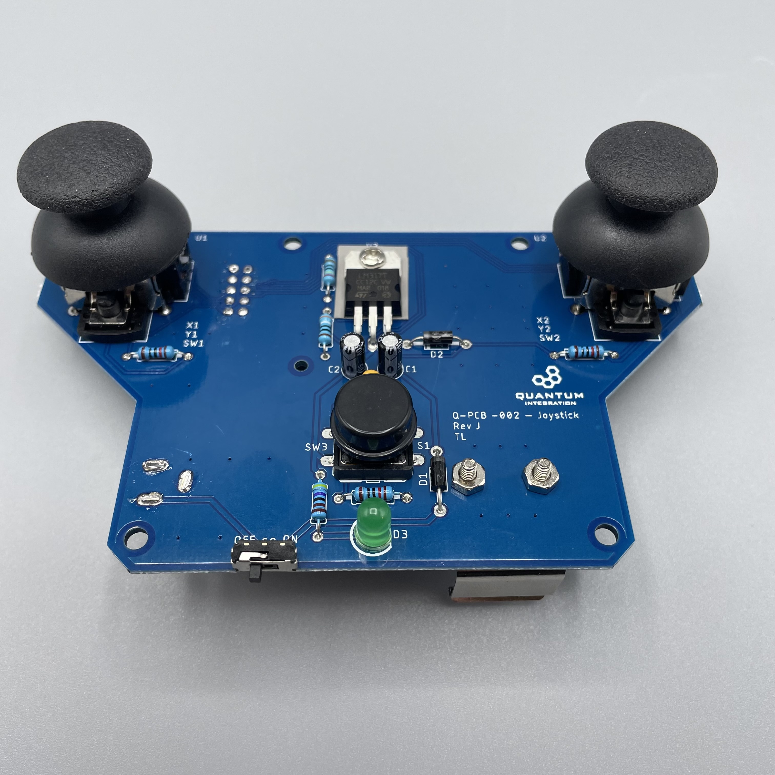
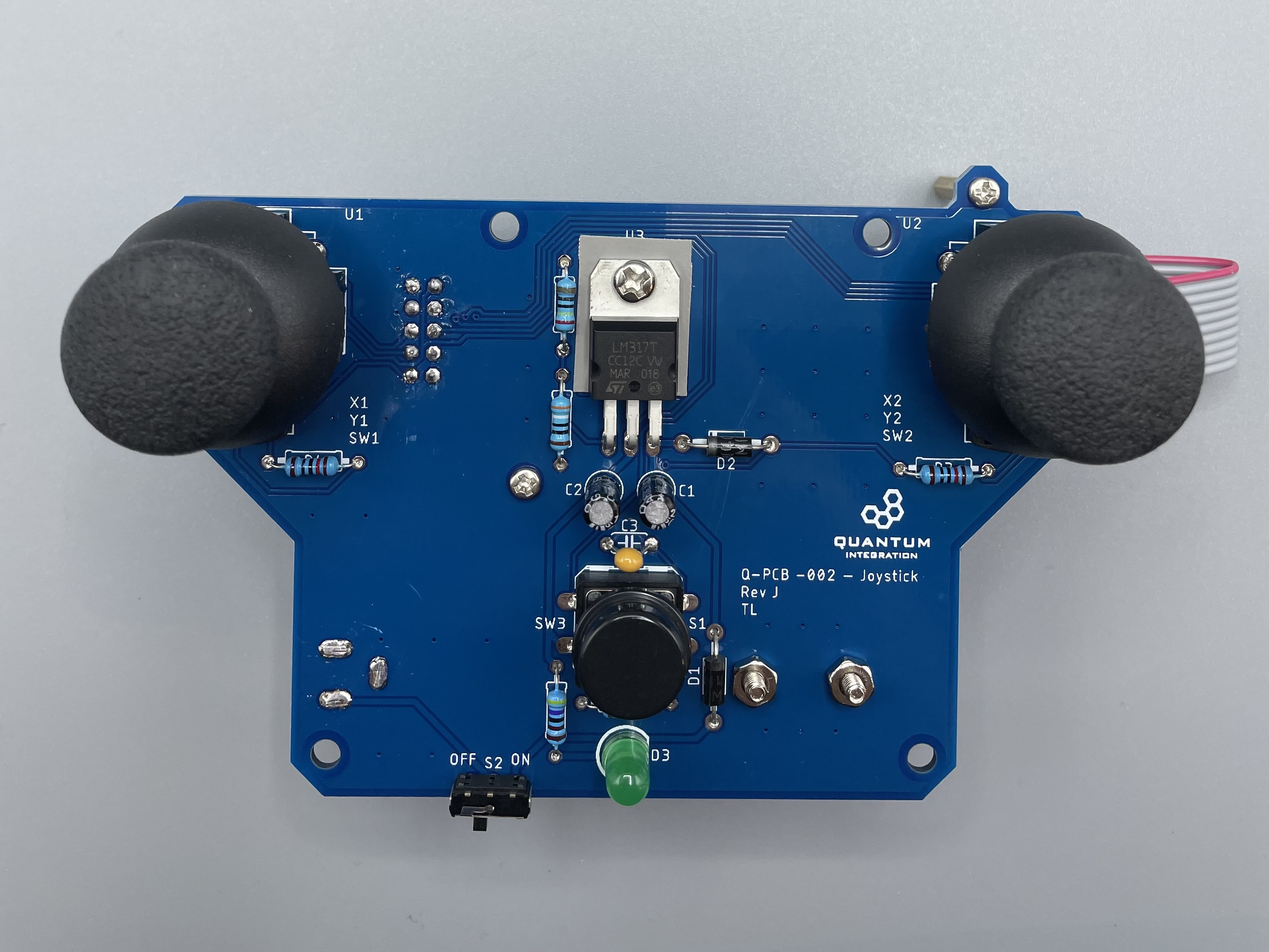
Take a look at the required components above and determine their final position on the PCB. The following images should be a good reference: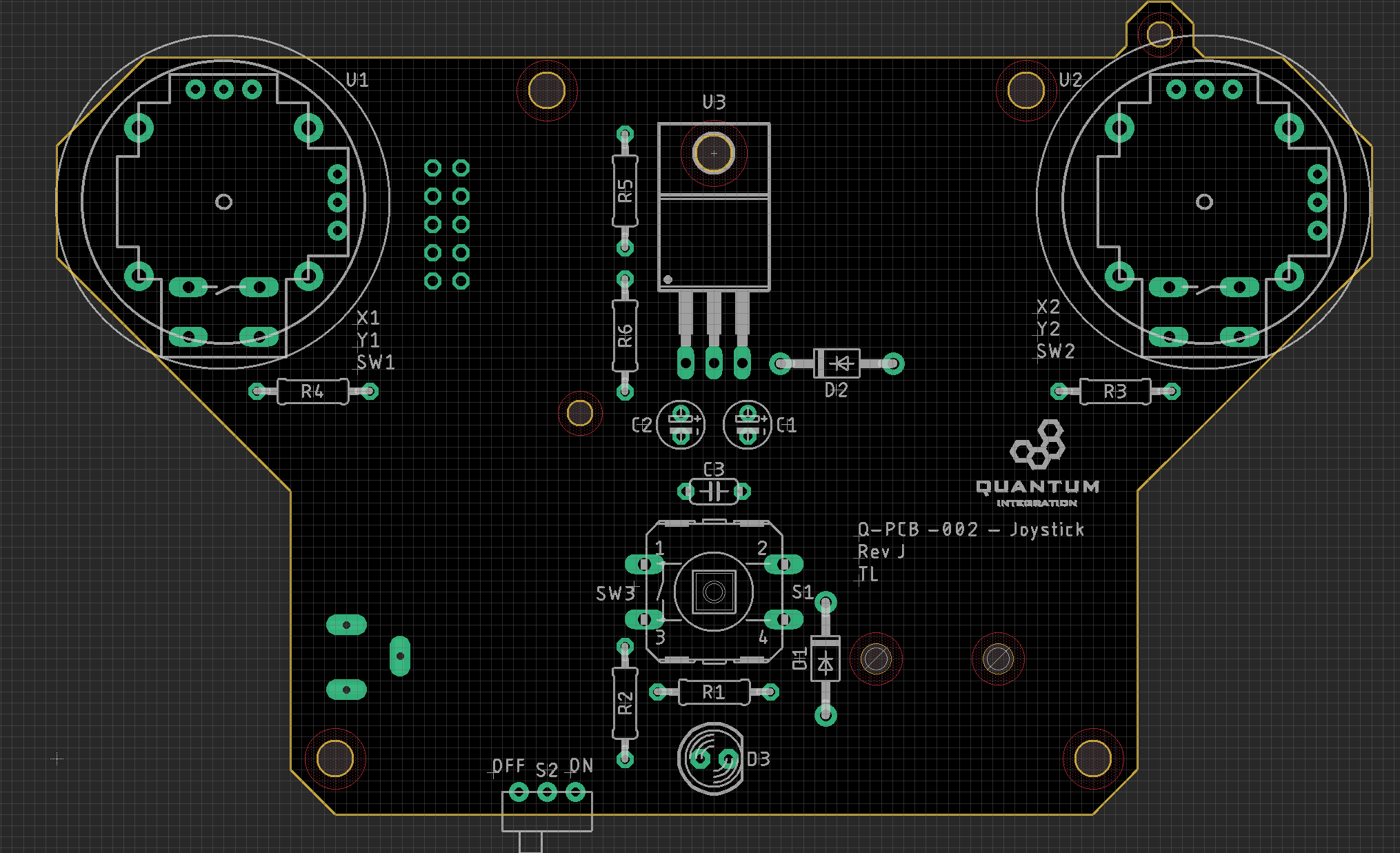
Place groups of components on the board and then solder them to the pads. It is recommended to
Using some form of work holder is advised. You can find a list of suitable work holders on our Recommended Tools List.

We will start by putting all the parts on the table.
If you are not familiar with soldering you should start with components with the lowest profile, like for example resistor resistors and them then move up to components like buttons with higher profile.
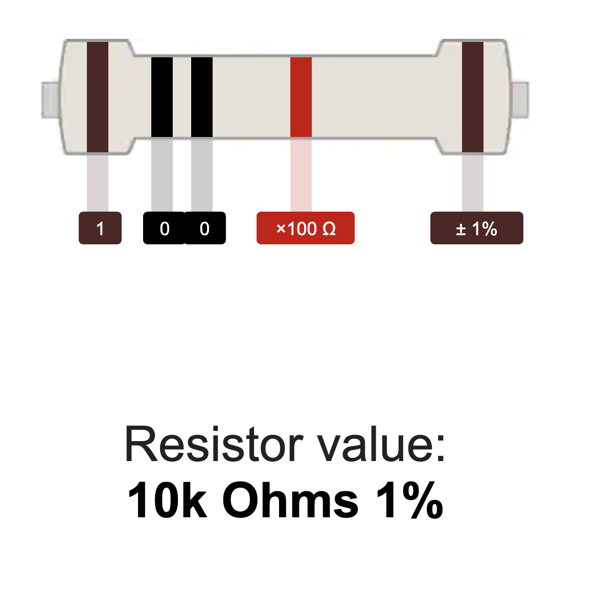
To determine the values of the given resistors and to place them in the correct position, please refer to a resistor color code calculator like this one:
Using some form of work holder is advised. You can find a list of suitable work holders on our Recommended Tools List.
First we gonna start with soldering the resistors.
240Ω Resistor : R5
390Ω Resistor : R6
4.7kΩ Resistor : R2
10kΩ Resistor : R1, R3, R4
 |  |  |  |
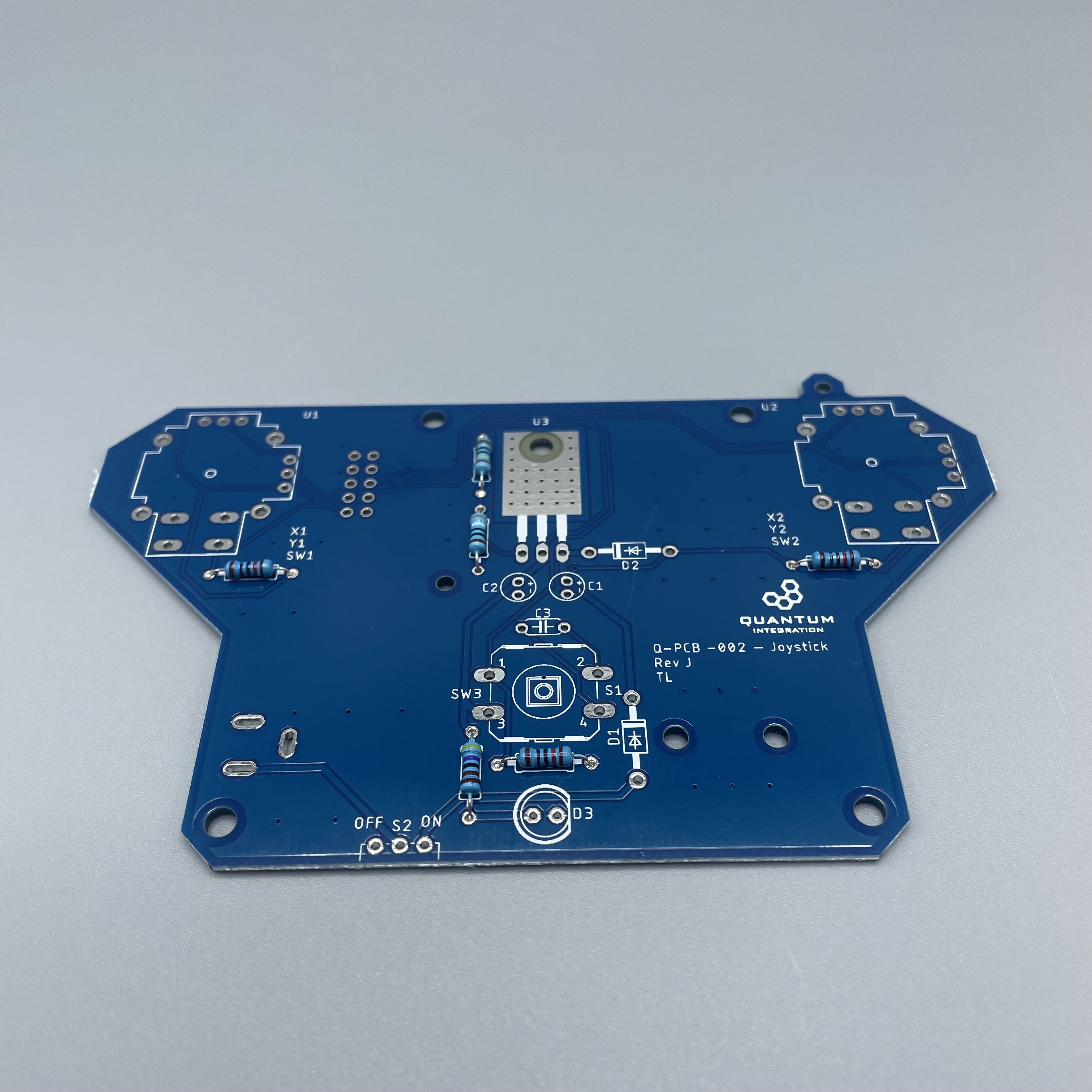
Solder the diodes. Make sure you put them in the right direction.
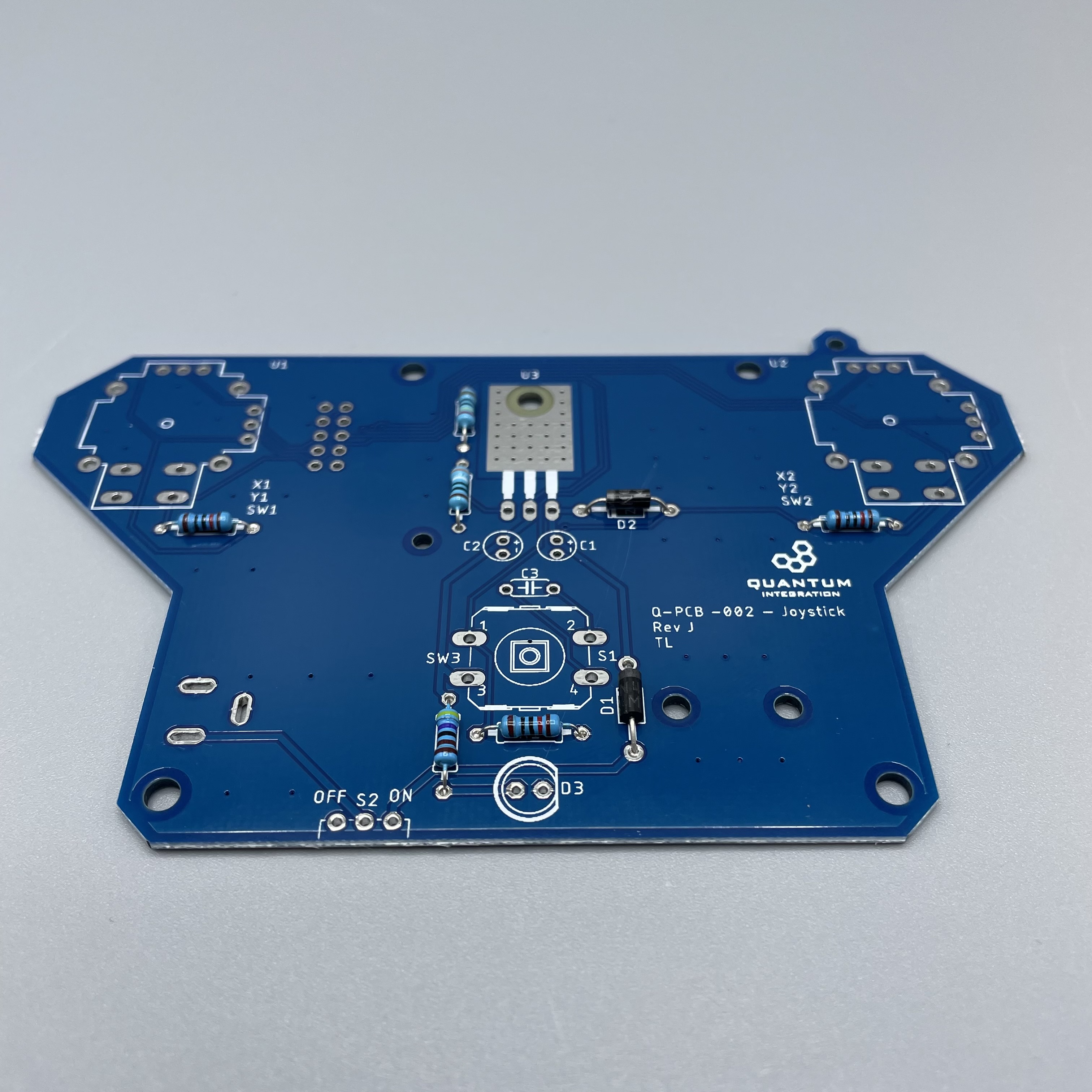
Solder the two polarized capacitors. 1µF for C2 and 0.22µF for C1. Remember the longer pin of the polarized capacitor is the positive side. The positive and negative side are labeled on the PCB.
Next comes the LED. It also has a positive and negative pin. The LED has a flattened side which is the negative side or pin. Orientate the LED so that it fits the schematic on the board on D3.
Next we solder the Switch. Make sure it points in the right direction facing away from the board. Also we are going to solder the heat sink. We included a pad to put between the regulator (U3) and the surface of the PCB. Use an M3 screw and nut from the kit to mount it and also don't forget to solder it.
Next solder the normal capacitor on C3. The direction isn’t important.
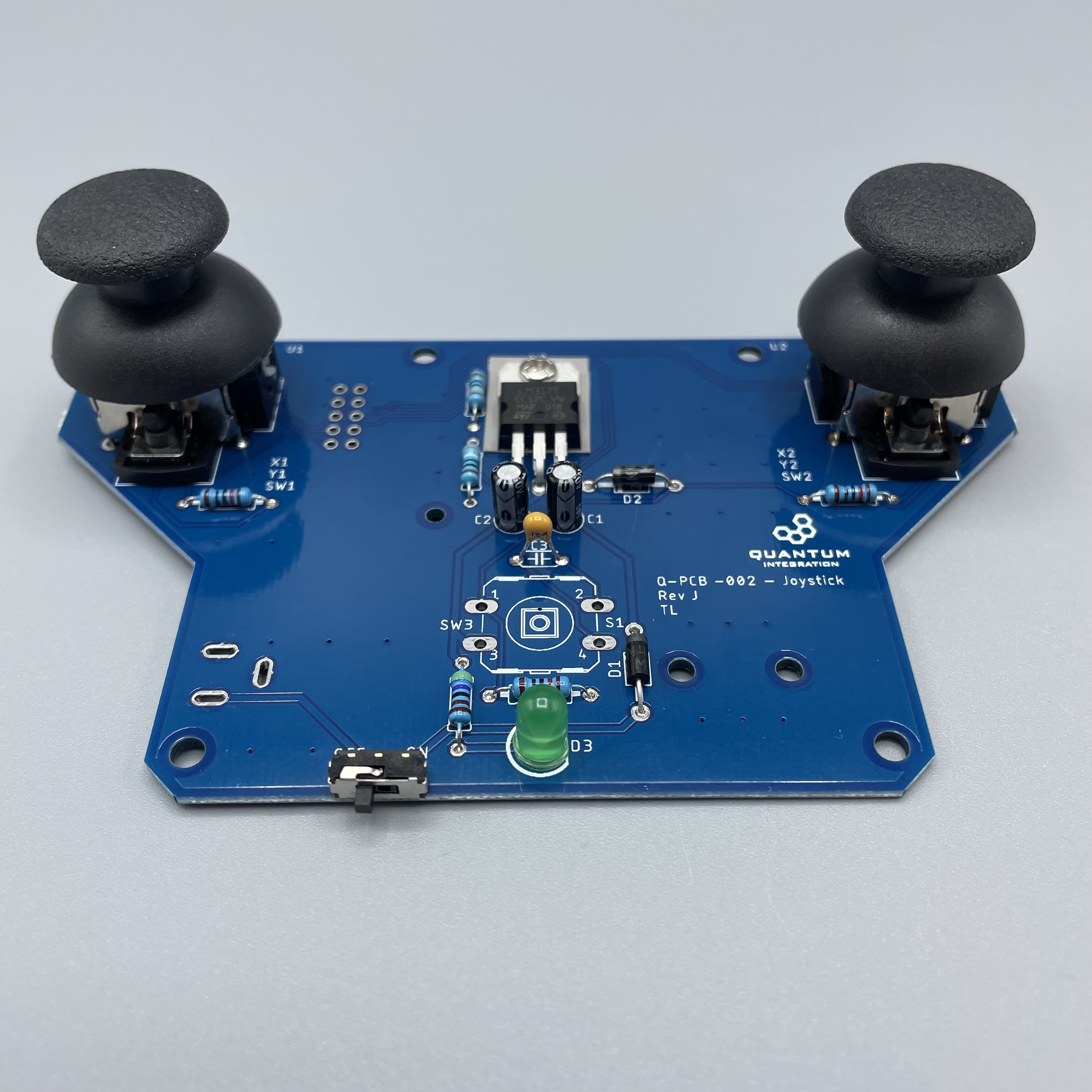
Step 2: Connecting to the Builder Base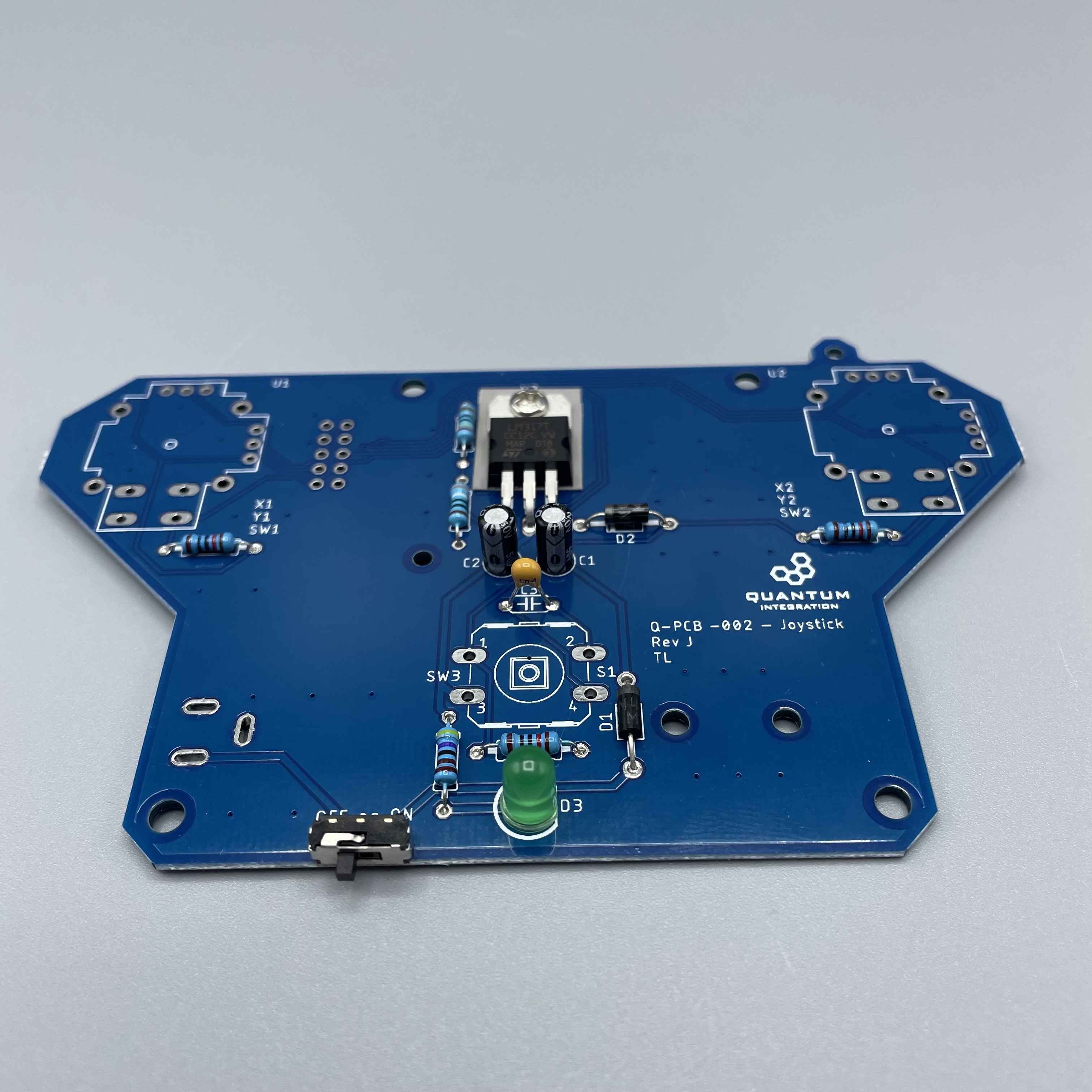
Next are the joysticks on U1 and U2. They will only fit in one direction. Make sure to solder every single pin of them!
Solder the single tactile button on S1.
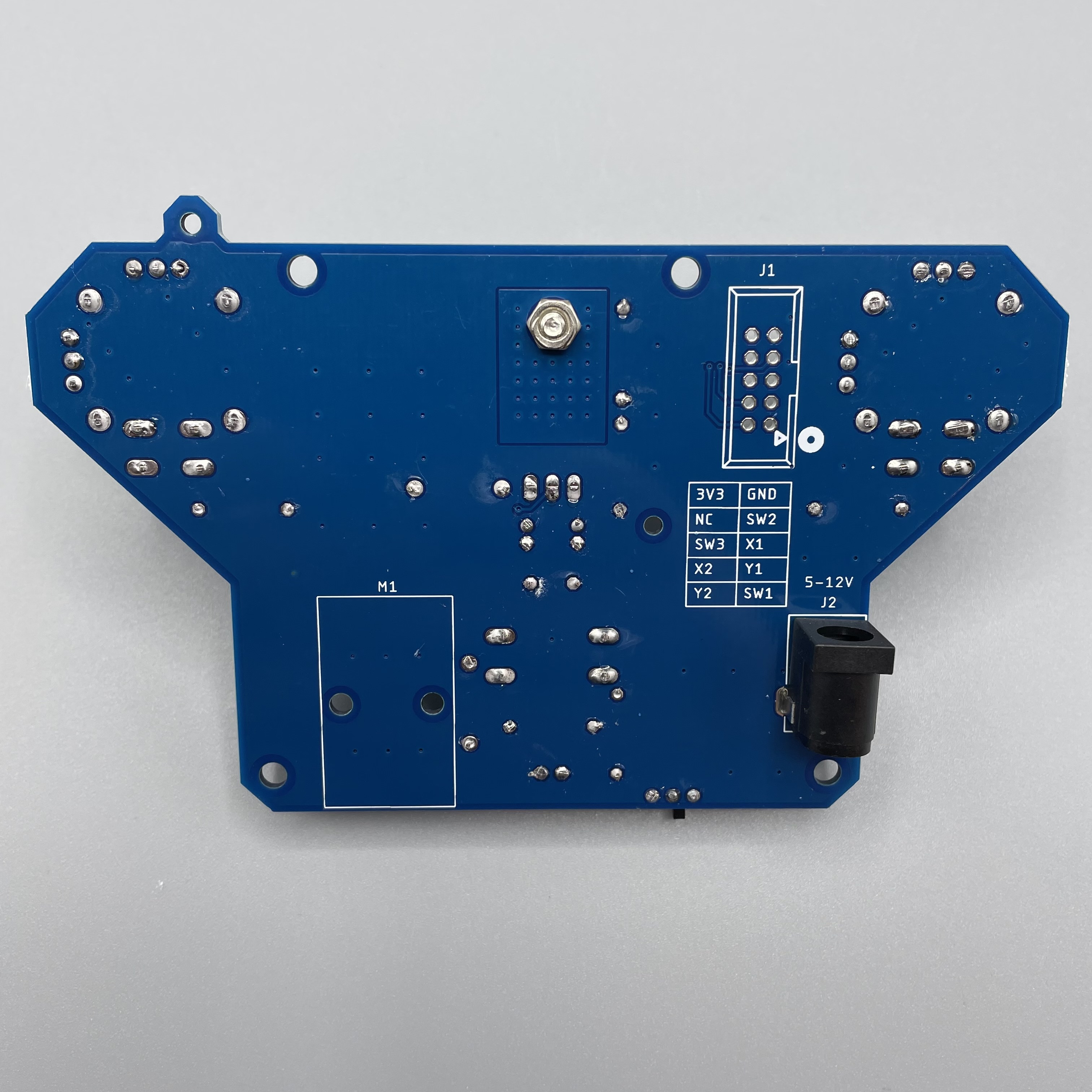
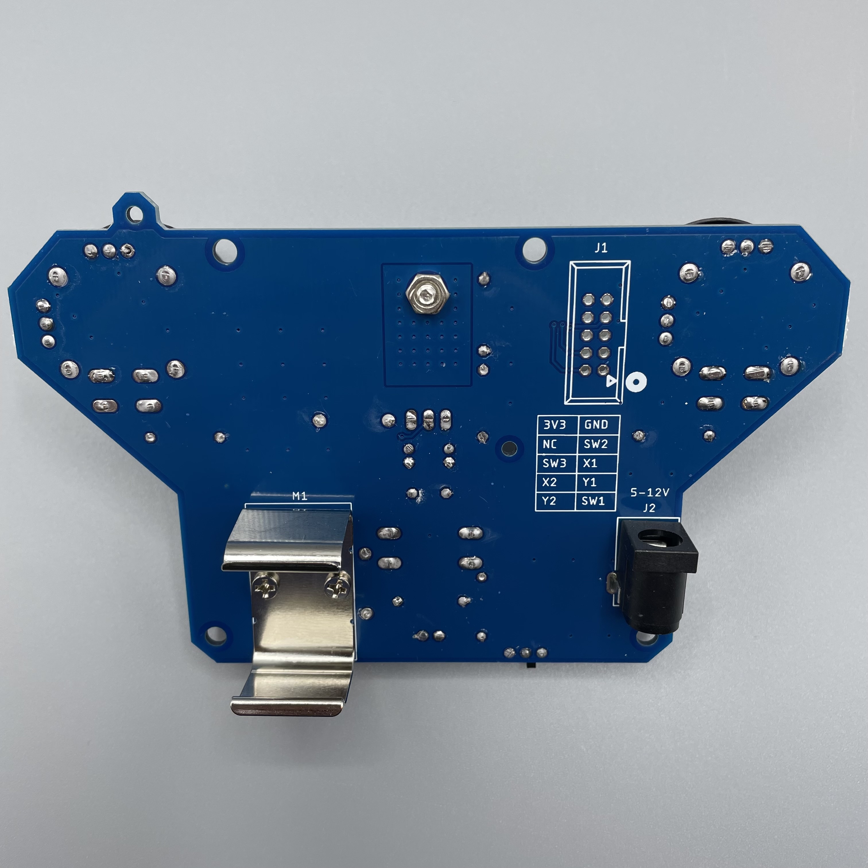
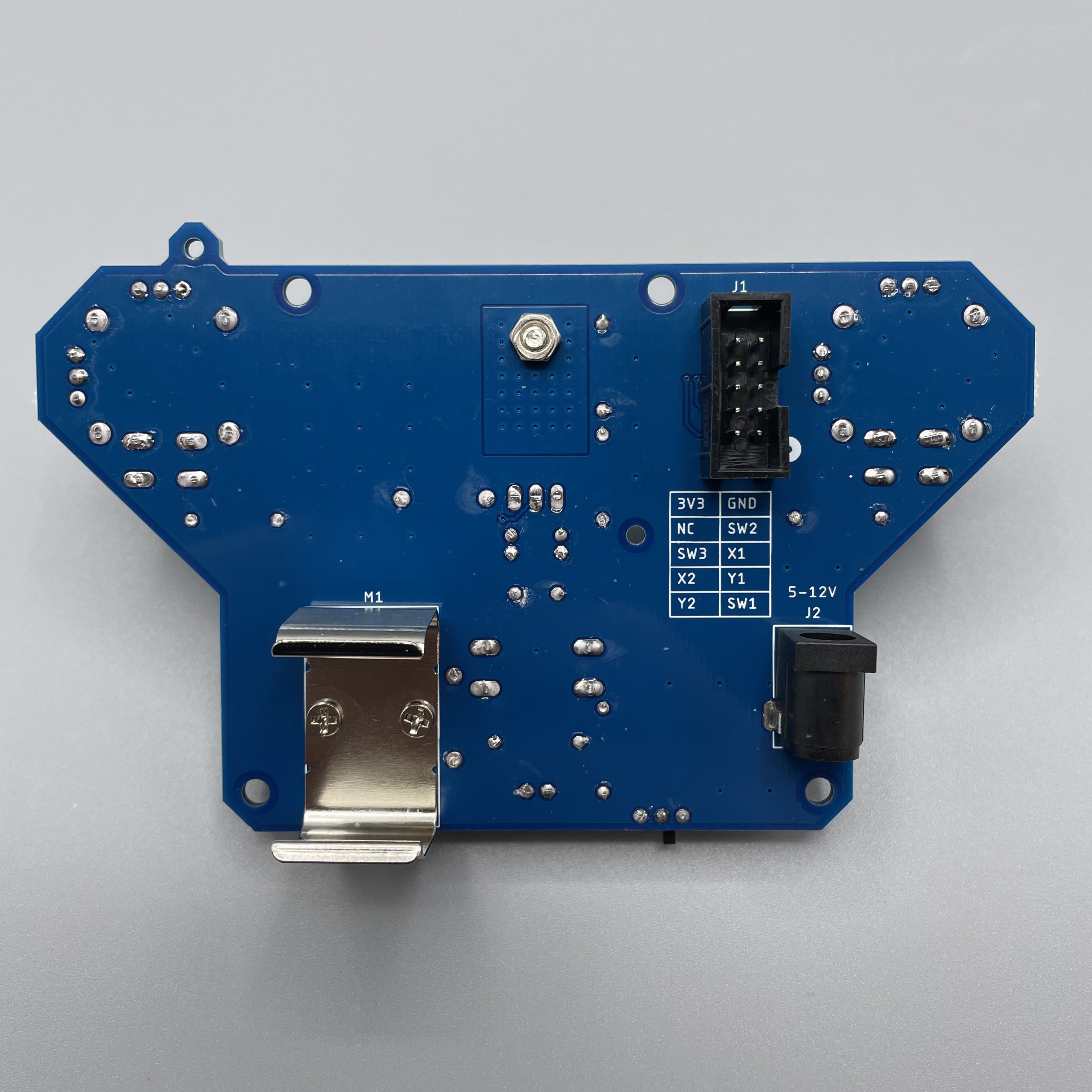
Now we solder the barrel jack onto the backside of the PCB since the battery holder is also on this side.
Now attach the battery holder. The screws should face up because they are flattened on their top so the battery will fit better in the holder.
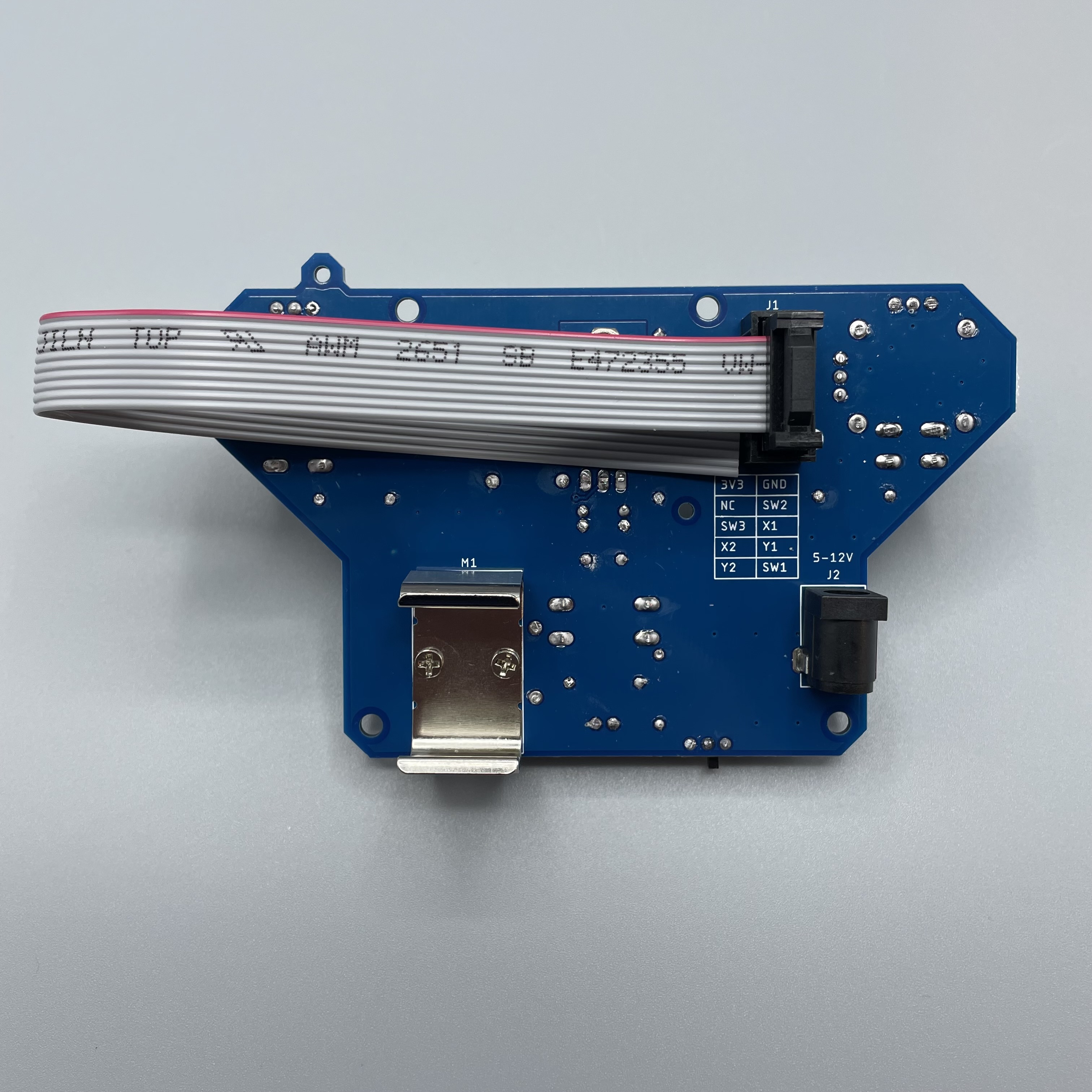
Solder the Ribbon connector on J1 but also on the bottom side of the PCB. The direction is important.
Lastly you can attach the ribbon cable but you don’t have to.
Your Joystick DIY Kit is ready to be used!
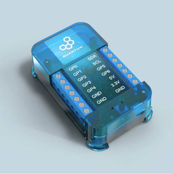
Connecting to the Builder Base
Refer to the following image to connect the Builder Base to the joystick.
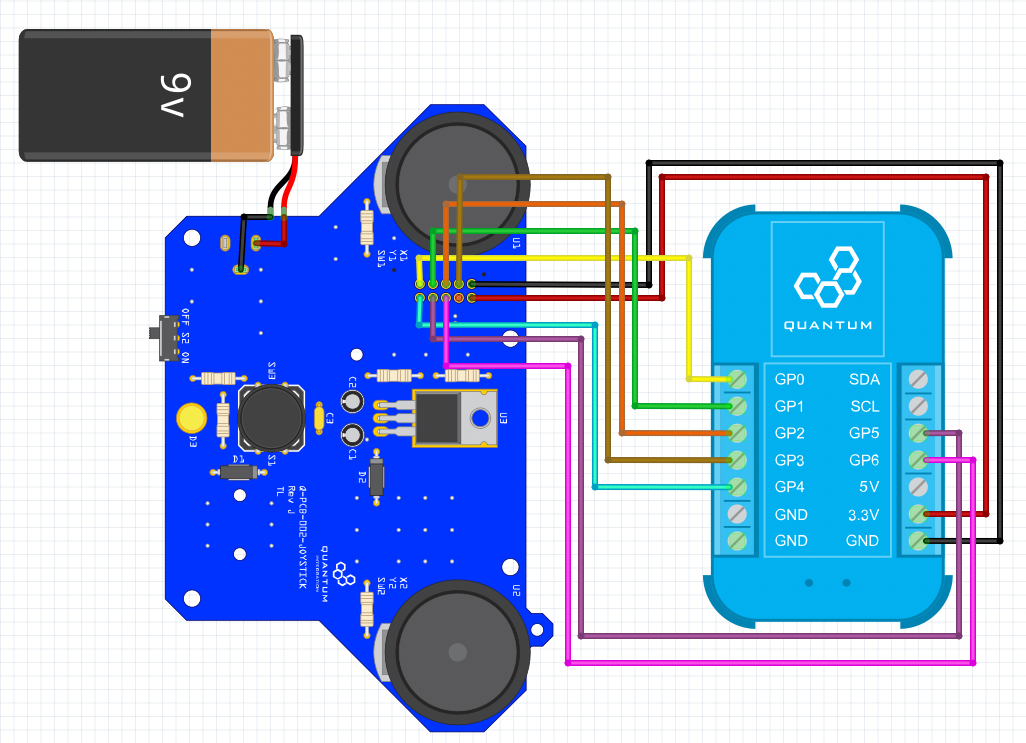
The joystick and the Builder Base will be powered by a 9V battery that can be attached to the joystick. Remember that the joystick connector gives 3.3V. When the power LED is light up the DIY Kit is ready to be used.
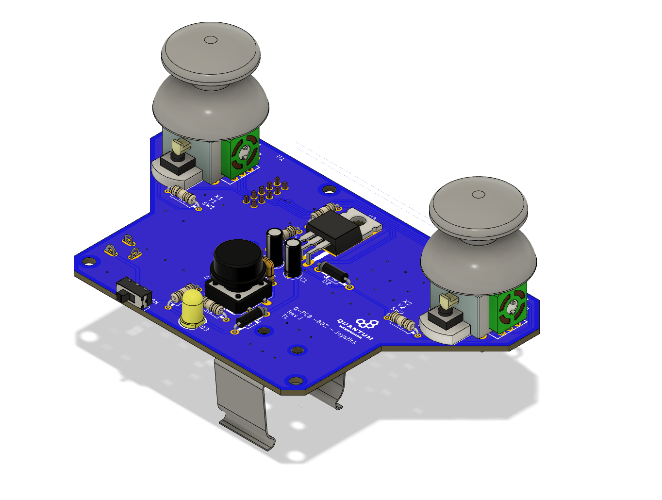
Please refer to the following picture for how we imagined the Joystick could be connected to implemented into a case with the Builder Base:
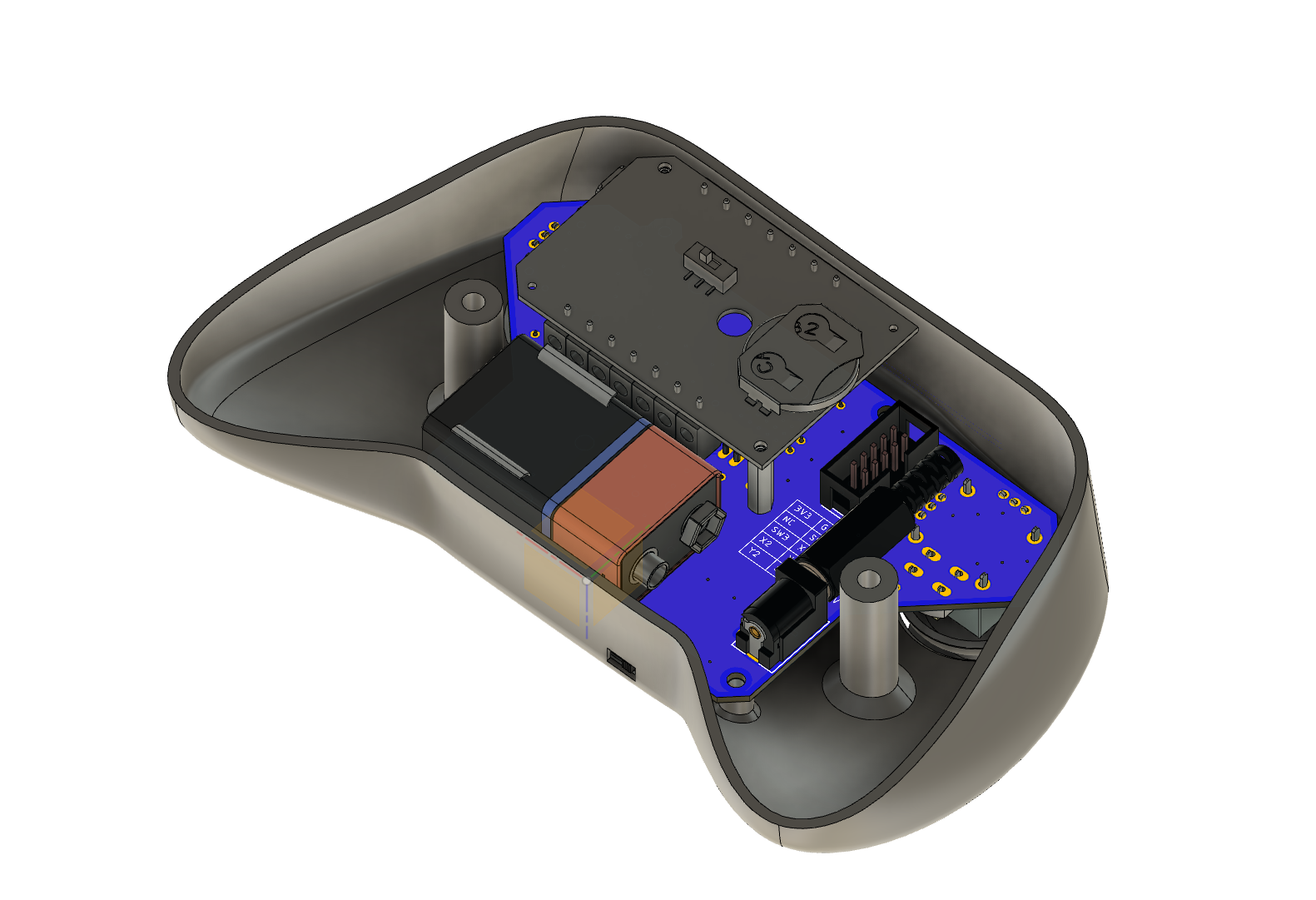
Follow the steps to get everything mounted accordingly:
mount the 9V battery holder to the bottom with M2.5 screws and nuts
free the Builder Base from its case and mount it to the bottom with M2 standoffs and screws
assemble the ribbon cable so it looks like the following
clip a 9V battery into the holder and connect it to the barrel jack with the harness contained in the kit
plug the ribbon cable in and connect the ends to the terminals of the Builder Base by splitting them apart
the ribbon cable connector is labeled and needs to be wired according to how the firmware is set up
We have a 3D file for a joystick case here:
| View file | ||
|---|---|---|
|
The upper case half case can be mounted to the PCB with 4 M3 screws that are included in the Kit. The lower half gets connected to the upper half with 2 M4 screws that are also included.
Projects
Joystick
The project page can be found here https://quantumintegrate.atlassian.net/wiki/spaces/QHD/pages/1240104961/Joystick%2B-%2BProject.
In this section we will explain how to make the DIY Kit compatible with the project.
After the Builder Base got connected to the bottom of the Joystick, the ends of the ribbon cable can be split and wired into the Builder Base. There is a little dot on the bottom of the PCB next to the ribbon cable connector indicating which pin is the most outer on after the cable is plugged in. Then there is a table explaining which pin is which in or output from the Joystick. Please wire the single wires from the ribbon cable to the client as follows:
SW1 → GP0
Y1 → GP1
X1 → GP2
SW2 → GP3
Y2 → GP4
X2 → GP5
SW3 → GP6
Then 3.3V gets connected which with each other, same procedure for GND.
The firmware file is different than in the project and can be found here:
| View file | ||
|---|---|---|
|
With these changes you can follow the instructions here and use the DIY Kit for this project: https://quantumintegrate.atlassian.net/wiki/spaces/QHD/pages/1240104961/Joystick%2B-%2BProject#Step-3%3A-Build-the-Application
Gallery
Resources
App & Firmware
|
|
This DIY Kit page is currently optimized for revision J.
Current revision
Assembly files for the current revision of the DIY Kit (Rev J): | https://github.com/QuantumIntegration/Q-PCB-002-Joystick-Hardware-Files/tree/Rev_J |
|---|
Older revisions
- | - |
|---|