| Table of Contents |
|---|
Overview
| Widget Connector | ||||||||||
|---|---|---|---|---|---|---|---|---|---|---|
|
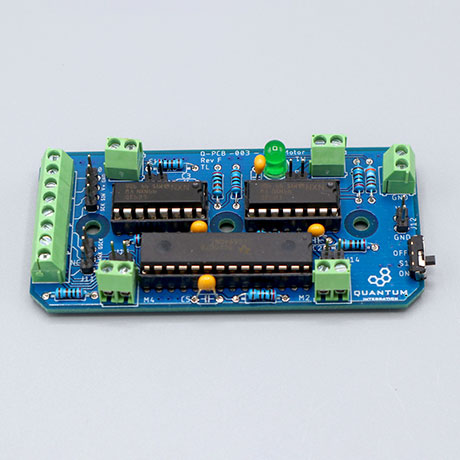
The Four Motor DIY Kit was built to familiarize our users with using PWM expander chips and H-bridges with our platform with a fun and approachable project. We used the Four Motor DIY Kit to build a Mecanum car. The car moves forwards and backwards, and turns like a tank by applying power to only one side. It can be use to drive any four low power motors though as well. This DIY Kit page is currently optimized for revision FThe full DIY Kit can be purchased here.
|
|---|
|
|
|---|
|
|---|
|
|---|
|
|---|
Hardware Components
The components are part of the DIY Kit or can be sourced separately with help of the BOM:
| View file | ||
|---|---|---|
|
Picture | Name | Designator | Quantity |
|---|
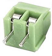
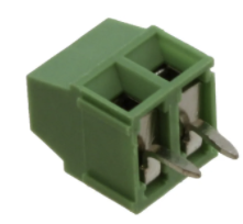 | 1x2 3.5mm Terminal Block | J1, J2, J3, J4, J5, J6, J7, J8, J9 | 9 |
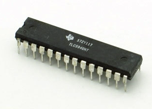 | TLC5940NT | U3 | 1 |
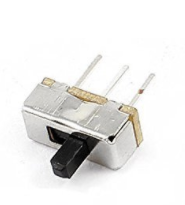 | Sliding Switch | S1 | 1 |
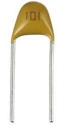 Reads: “104“ | 100nf Capacitor | C2, C4, C5 | 3 |
Reads: “105“ | 1uf Capacitor | C1, C3 | 2 |
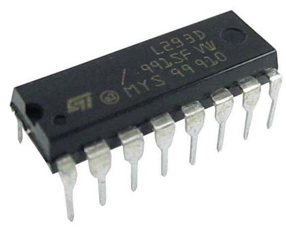 | L293D | U1, U2 | 2 |
 | 2kΩ Resistor | R2, R3, R4, R5, R6, R7, R8, R9, R10 | 9 |
 | 3.9kΩ Resistor | R1 | 1 |
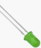 | Radial LED (5mm) | D1 | 1 |
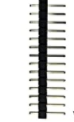 | 1x2 pin header | J12, J13, J14, J15, J16 | 5 |
| 1x3 pin header | J11 | 1 |
| 1x4 pin header | J10 | 1 |
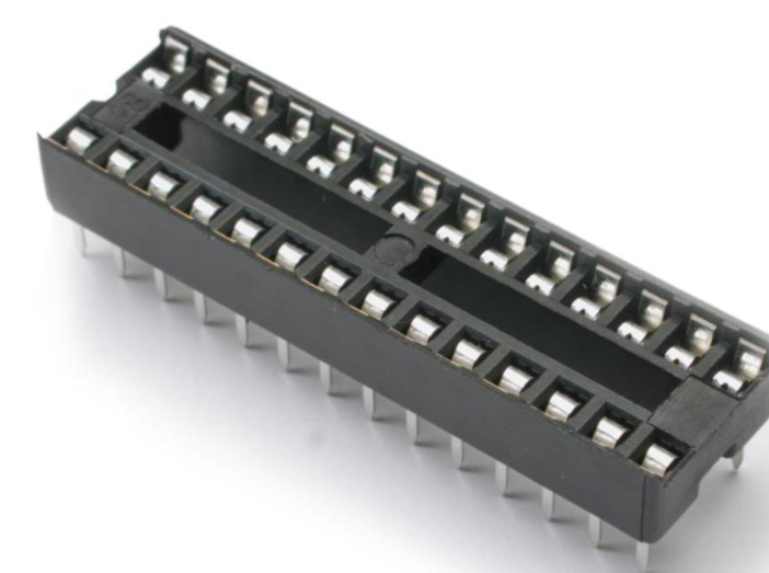 | 28 pin carrier | 1 | |
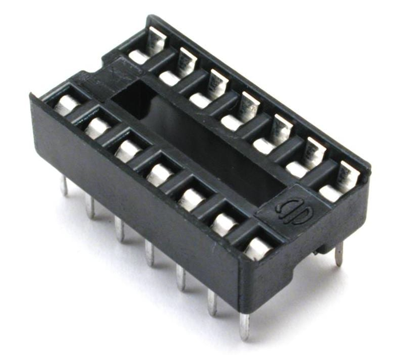 | 14 pin carrier | 2 | |
 | Four Motor PCB | Q-PCB-003 | 1 |
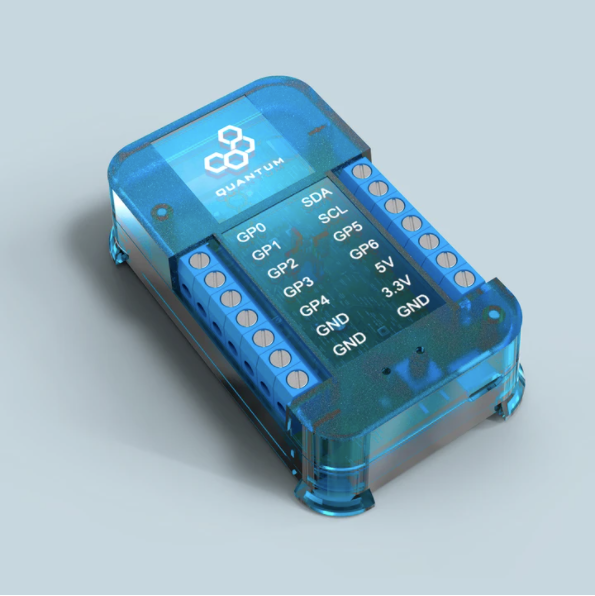
Q-Client Builder Base
1
Tools Used
Picture | Name | Quantity | Link |
|---|---|---|---|
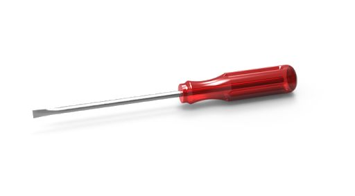 | Small slotted-head screwdriver | 1 | Included in |
or you can pick from one on our Recommended Tools List | |||
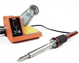 | Soldering Iron | 1 | You can pick from one on our Recommended Tools List |
 | Solder | 1 | You can pick from one on our Recommended Tools List |
 | Diagonal Cutters | 1 | You can pick from one on our Recommended Tools List |
 | Work Holder | You can pick from one on our Recommended Tools List |
Story
The Idea
The Quantum revision on the Four Motor kit was built to familiarize our users with using PWM expander chips and H-bridges with our platform with a fun and approachable project.
Video
| Widget Connector | ||||||||||
|---|---|---|---|---|---|---|---|---|---|---|
|
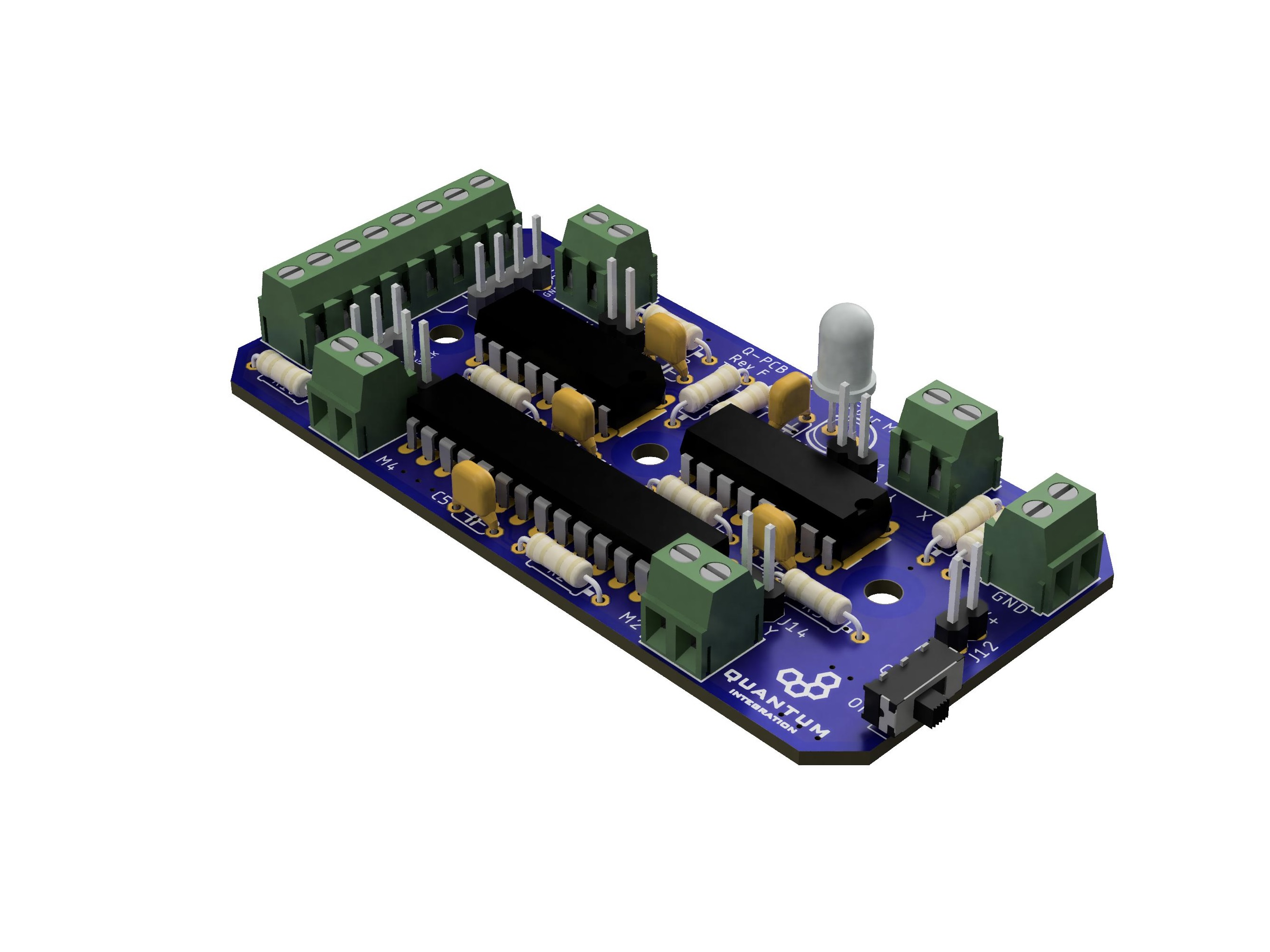
PCB Assembling and Soldering
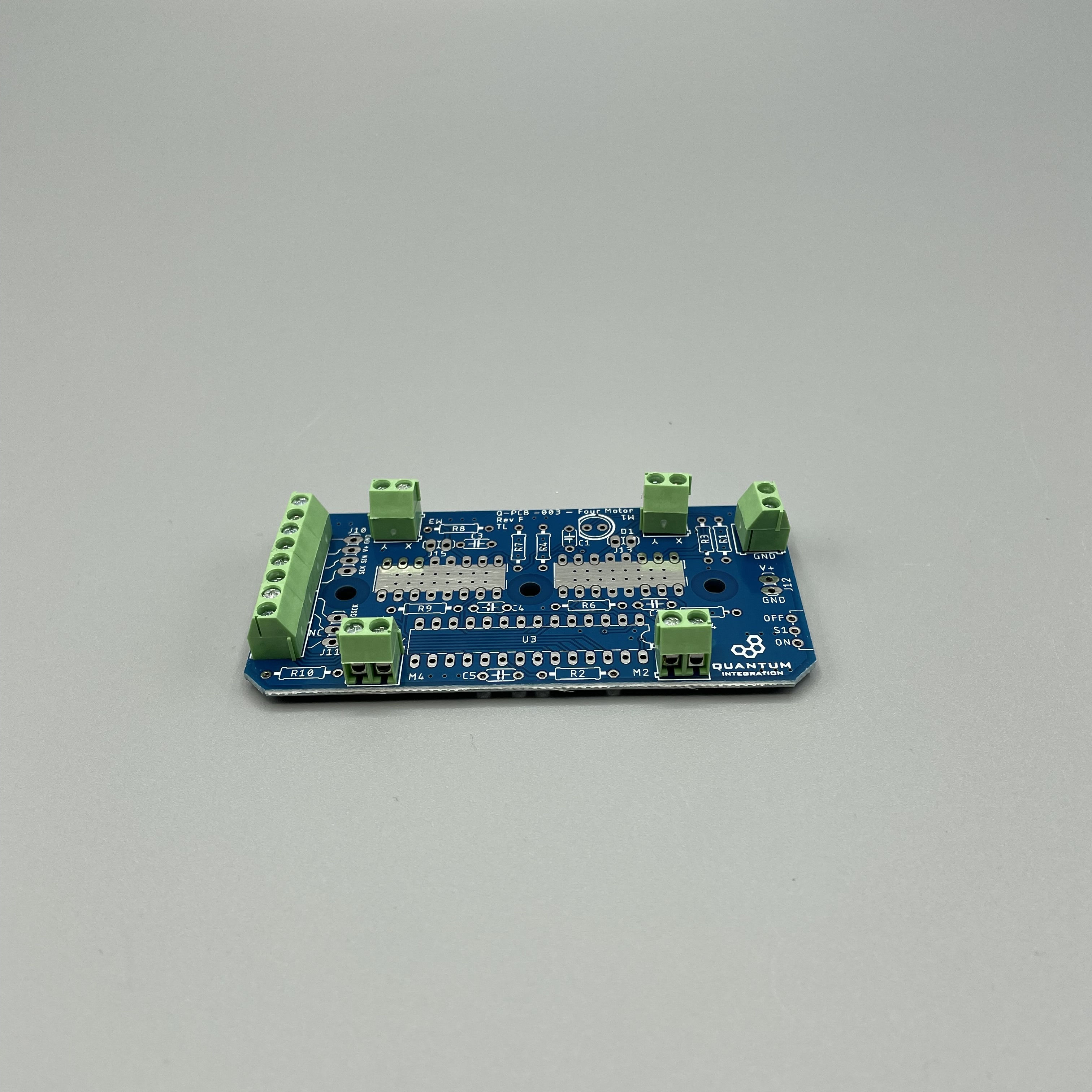
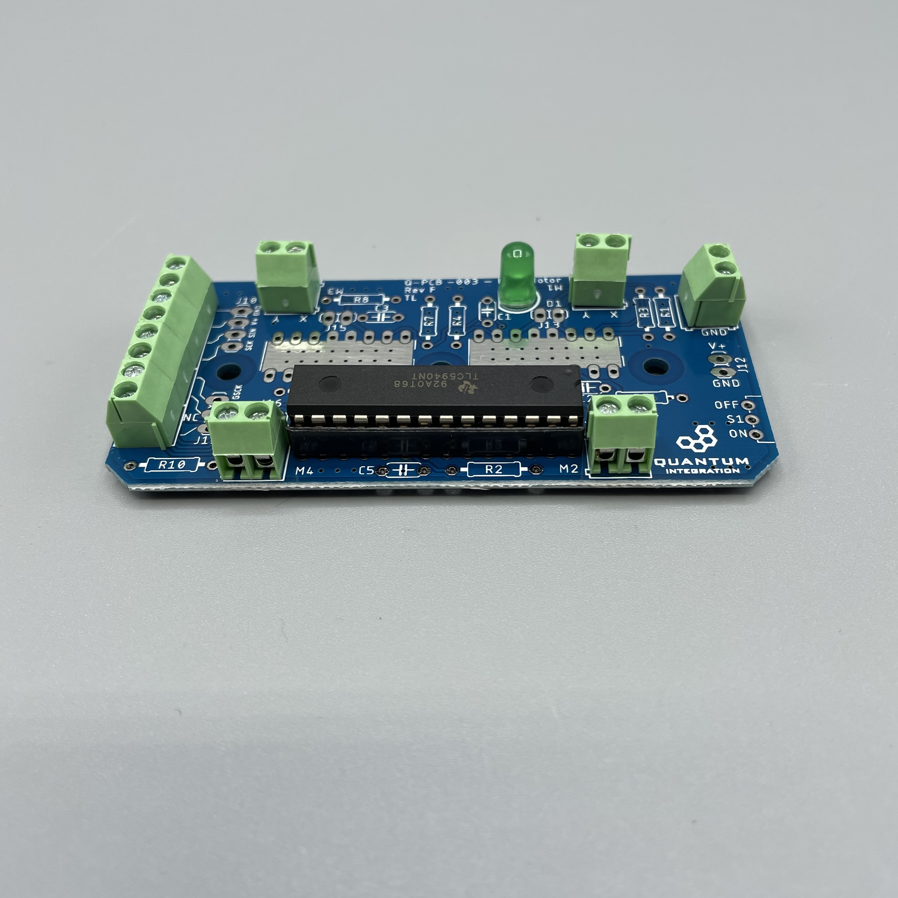
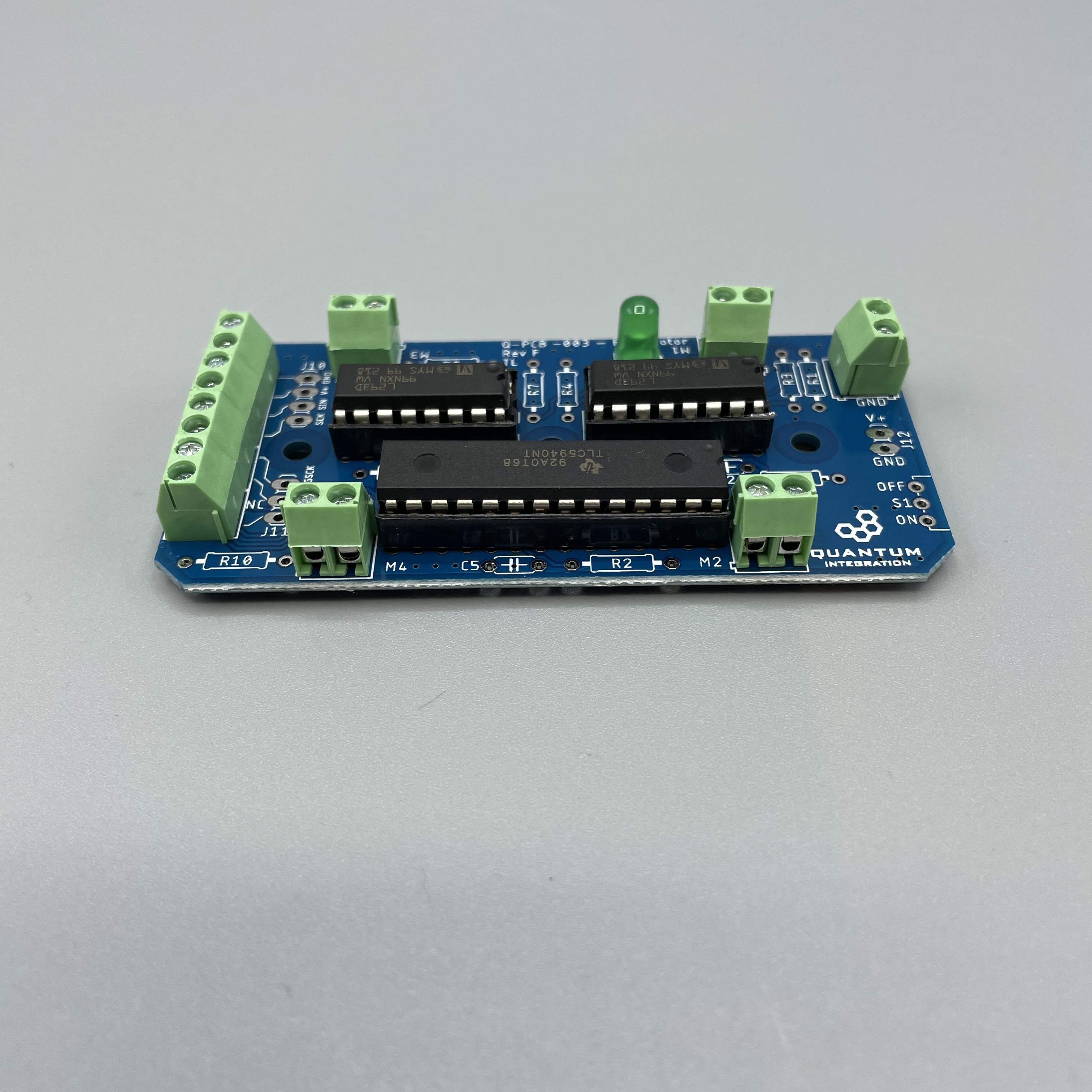
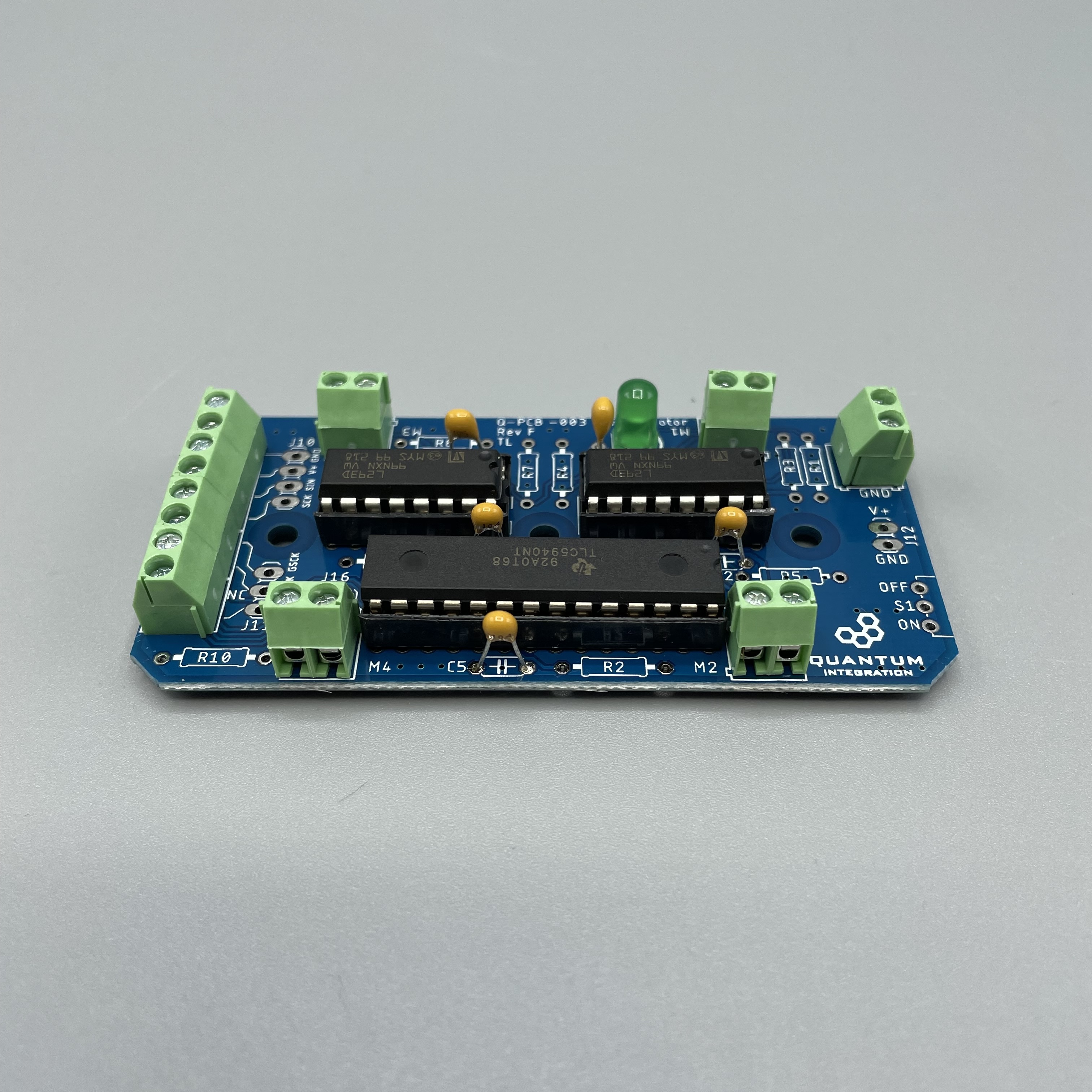
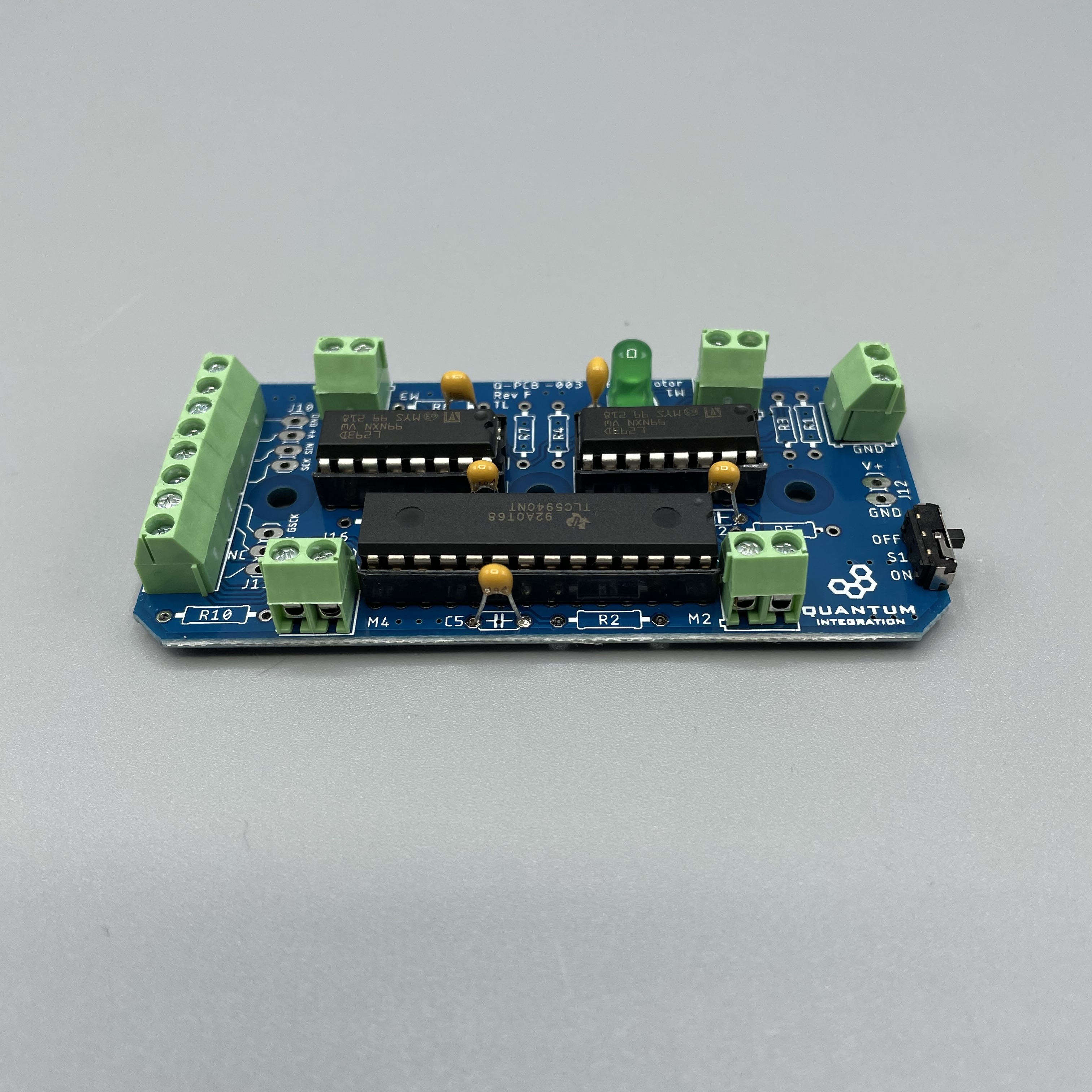
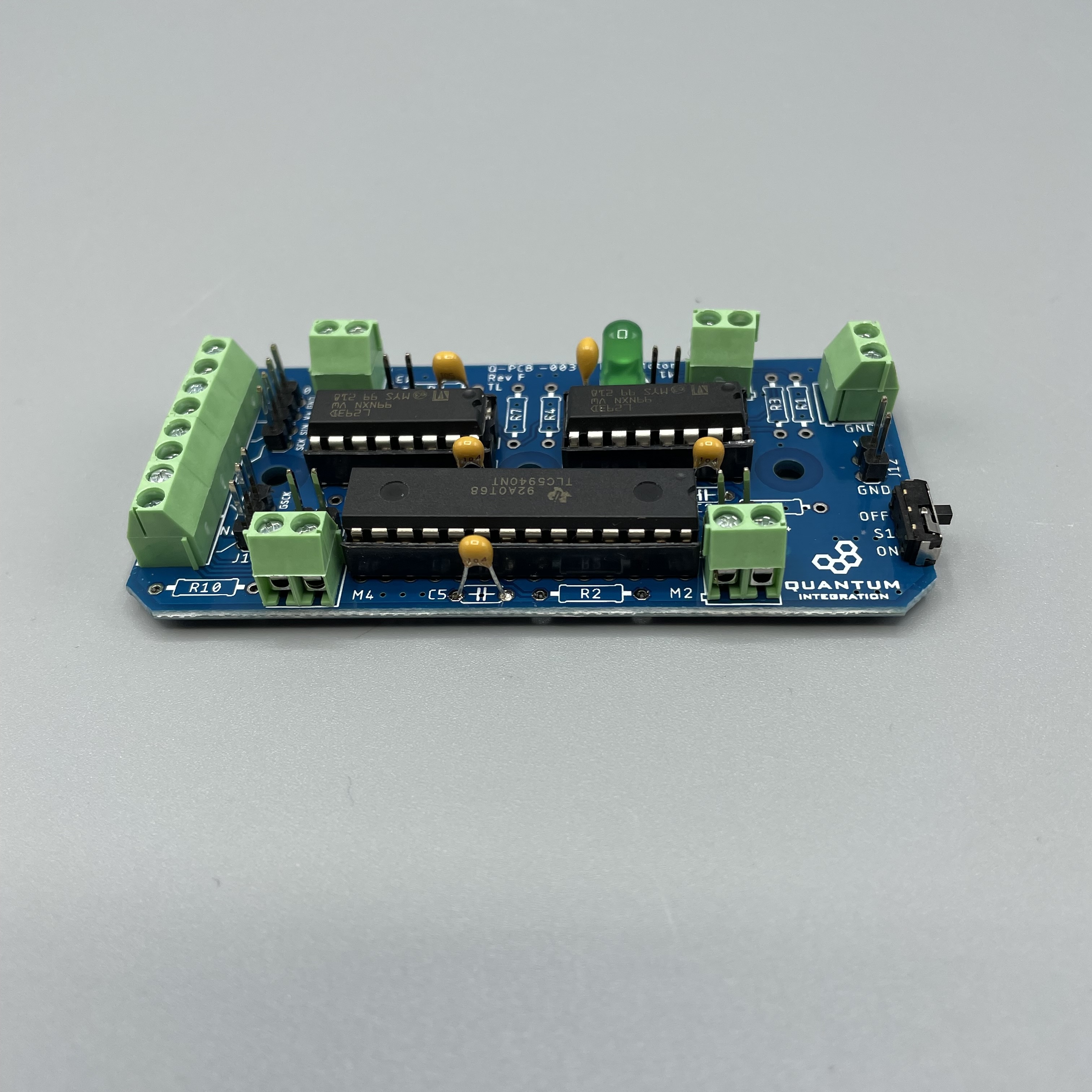
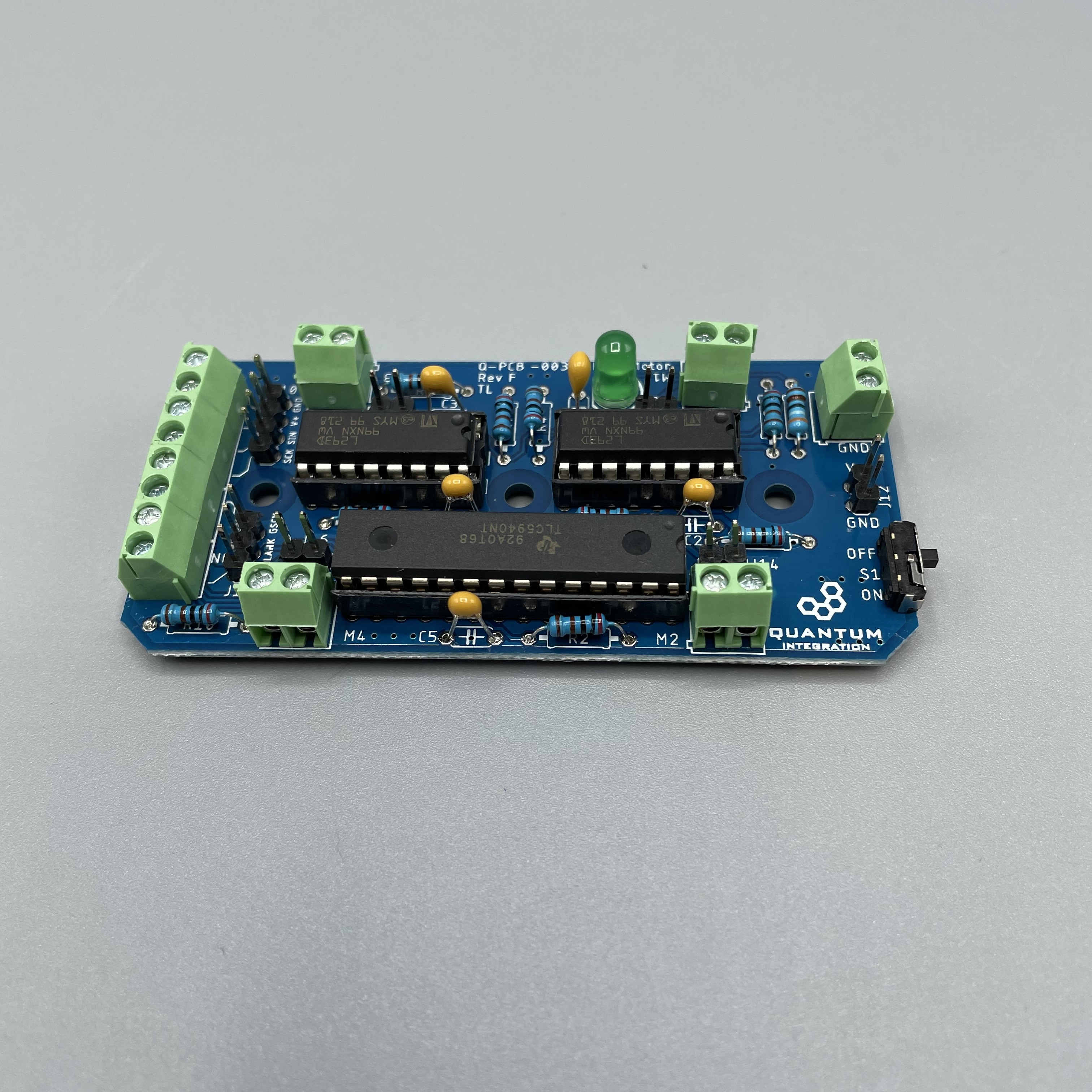
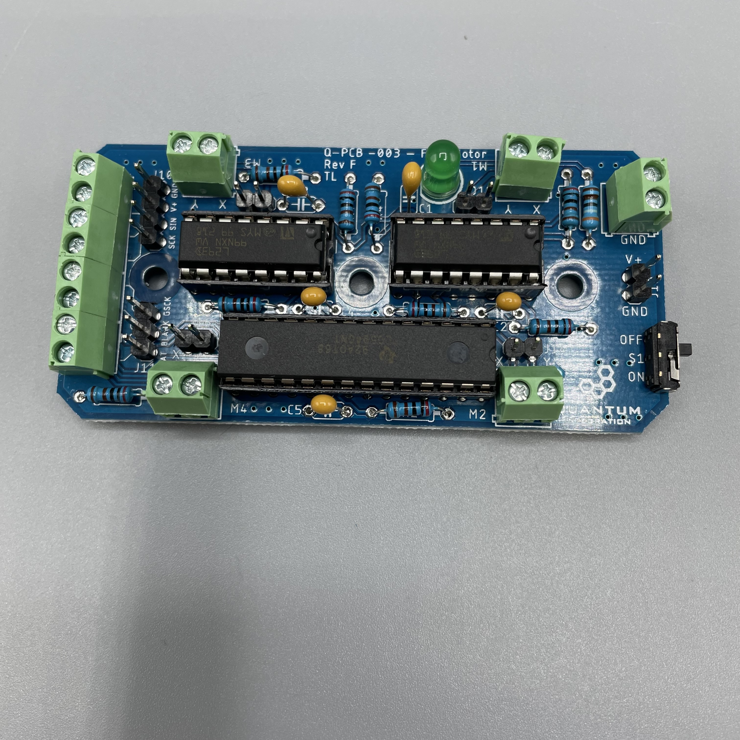
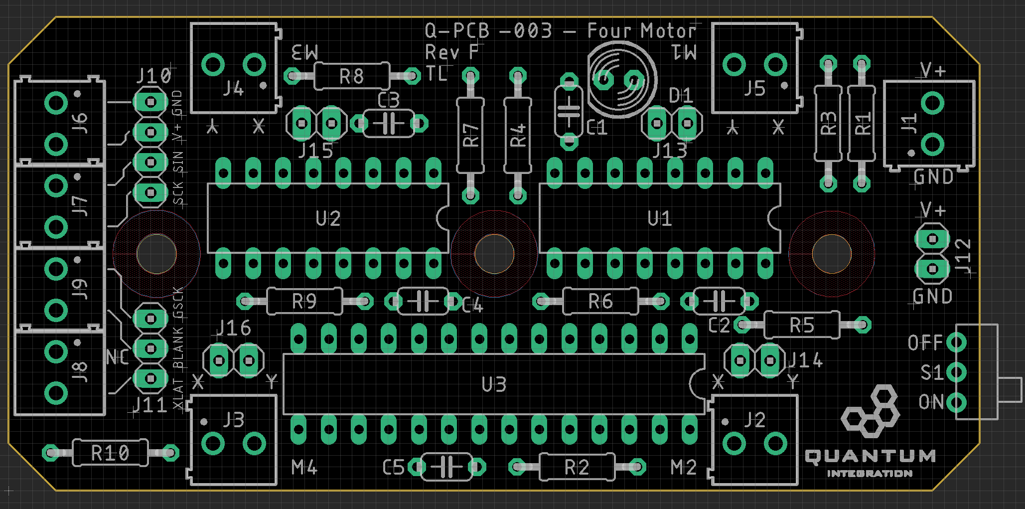
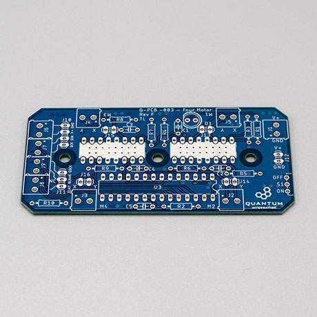
Take a look at the required components above and determine their final position on the PCB. The following images should be a good reference:
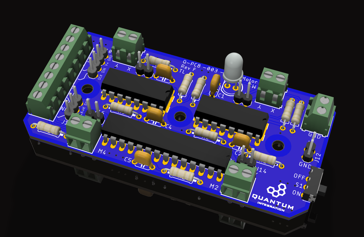
Place groups of components on the board and then solder them to the pads. It is recommended to start with components with the lowest profile, like for example resistor and them move up to components like buttons with higher profile.
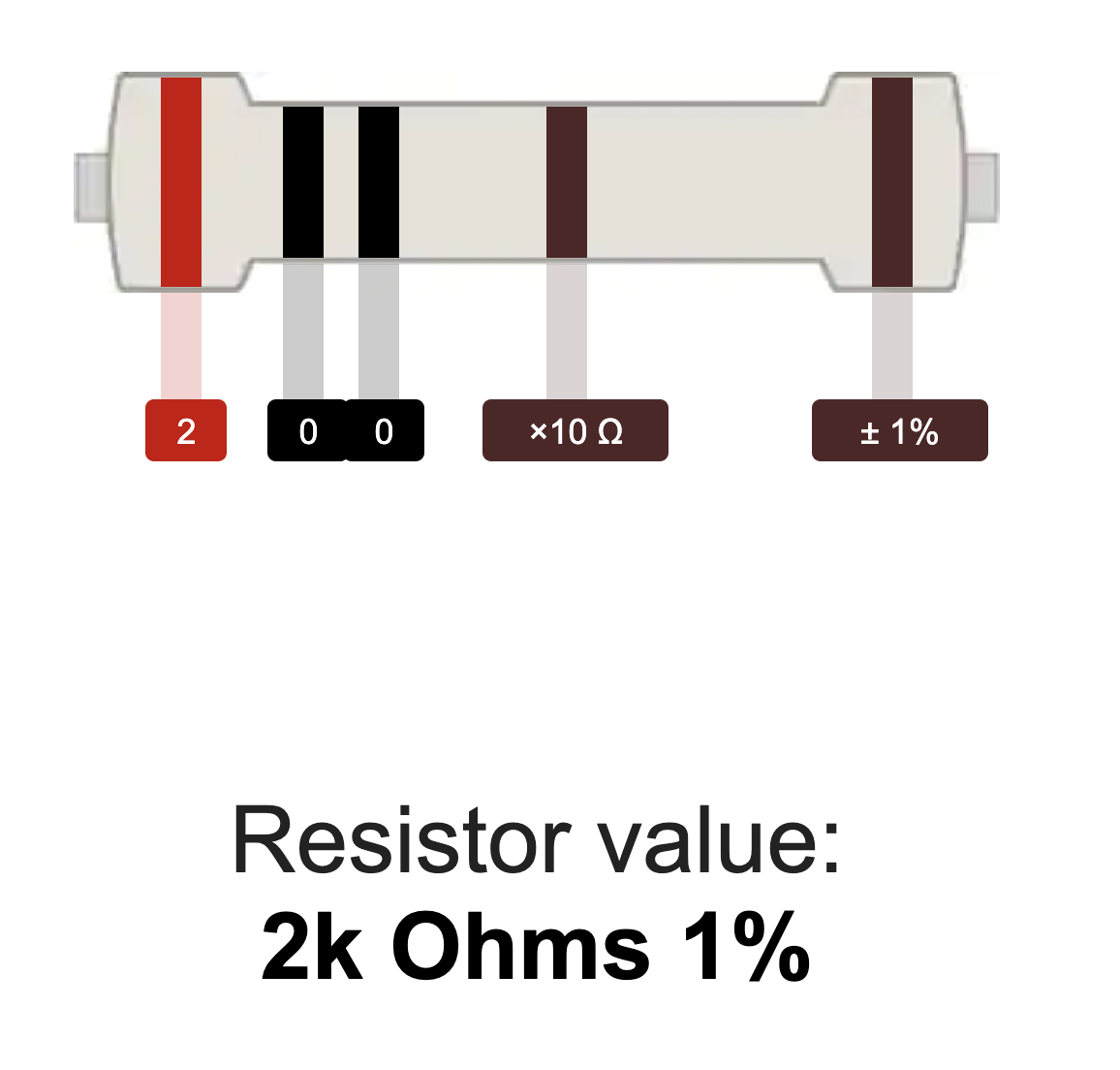
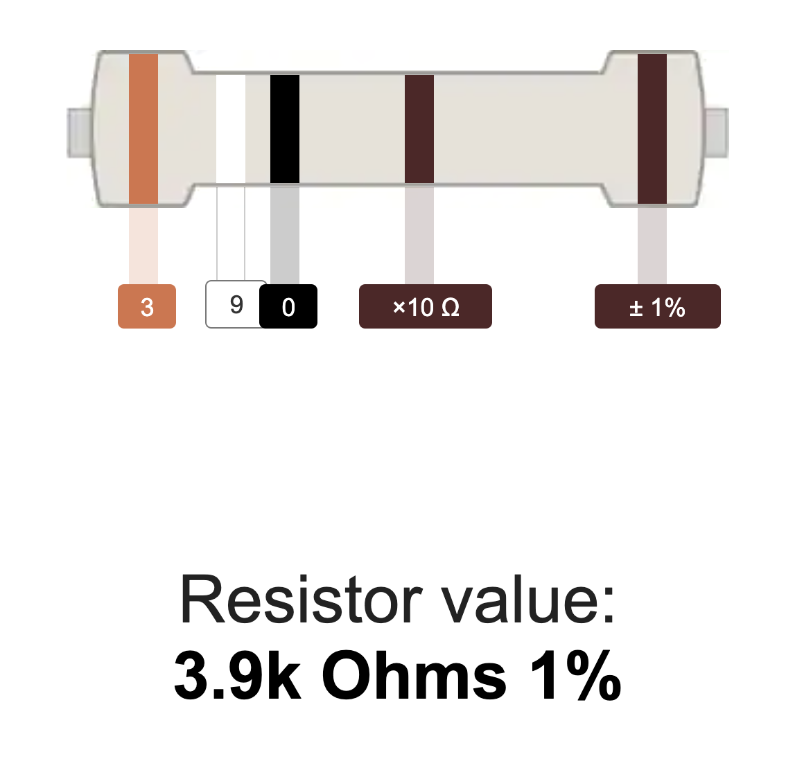
To determine the values of the given resistors and to place them in the correct position, please refer to a resistor color code calculator like this one:
Using some form of work holder is advised. You can find a list of suitable work holders on our Recommended Tools List.
To help you placing the bigger chips for the PWM expansion and the motor drivers, we put a 28-pin carrier and two 14-pin carriers into the kit. These can be soldered down and the chips can simply be plugged in on top of the carrier.
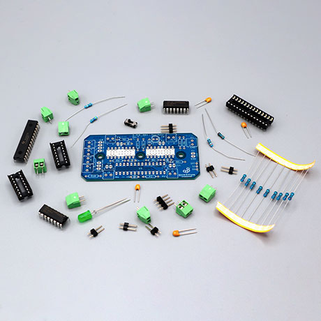
Step 2:
We will start by putting all the parts on the table.
First solder the terminal blocks. Make sure they are looking in the right direction.
Next solder the LED.

Solder the TLC5940NT with its 28 pin carrier. Make sure the directions are right. The board will show you how to place it.
Do this as well with the two L293D and their 14 pin carriers. Make sure the directions are right. The board will show you how to place it.
Next are the capacitors. C1 & C3 have 1µF. C2, C4 and C5 have 100nF. Solder them on their dedicated places.
Solder the switch. It should face away from the board.
Now the pin headers. Make sure they aren't upside down.
Next are the resistors.
2k Ohm: R2, R3, R4, R5, R6, R7, R8, R9, R10
3.9k Ohm: R1
Your Four Motor DIY Kit is ready to be used!
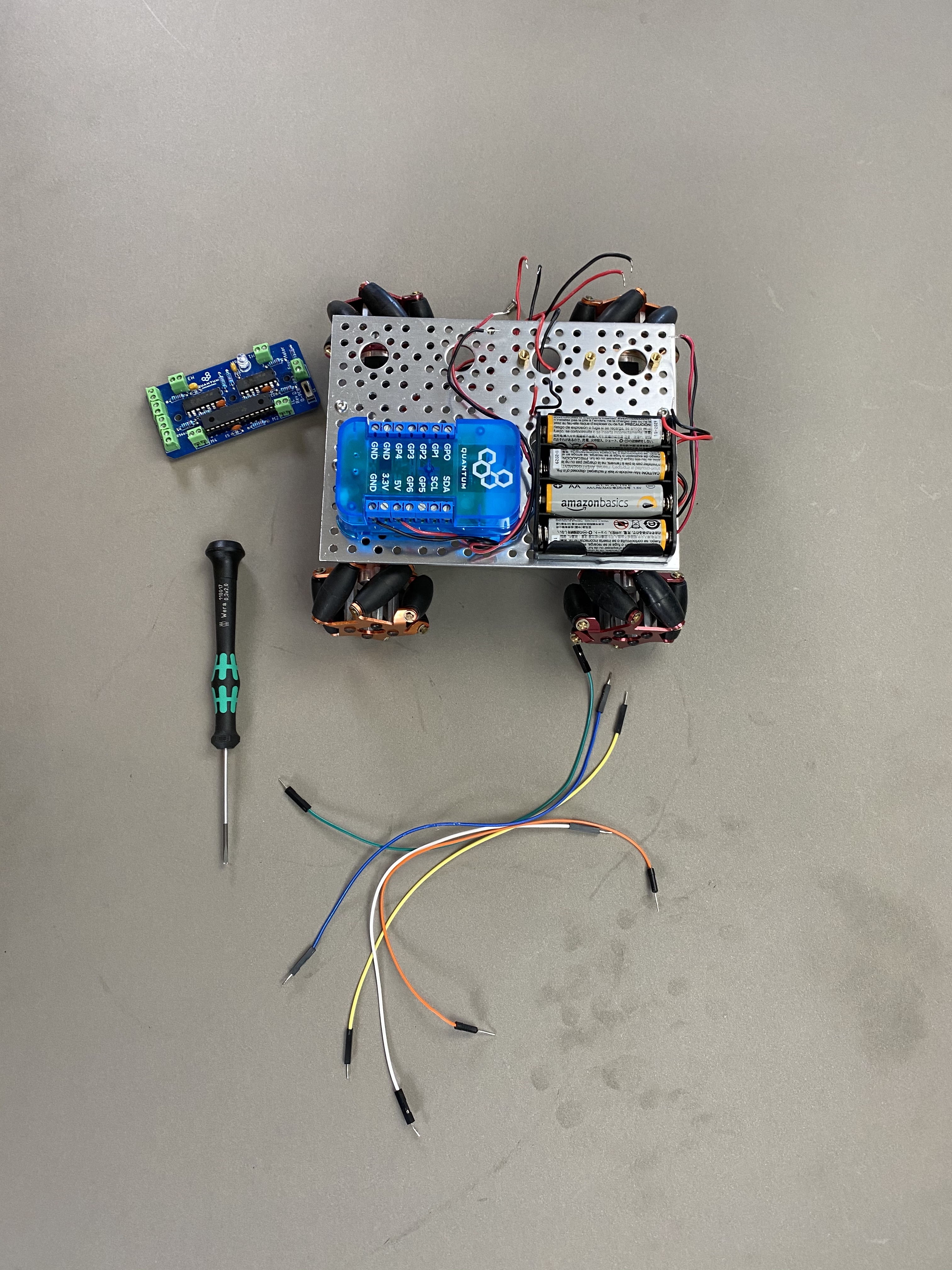
Connecting to the Builder Base
To connect the DIY Kit to the Builder Base you will need a bunch of male to male jumper wires and your flathead screwdriver.
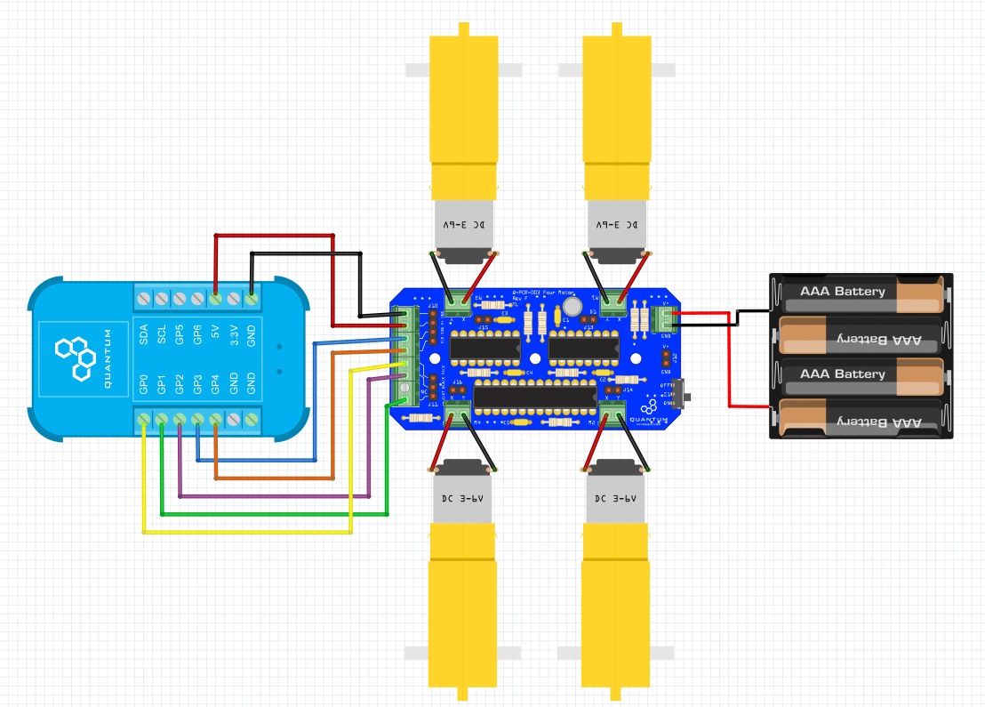
Please connect the Builder Base to the wide 8-connection jumper on the DIY Kit. The labeling of the connectors will be the same as determined in your firmware. The Builder Base can now get powered via USB and power the Kit as well, or get powered through the Kit. For that, the 2- connection terminal on the opposite side of the Kit has to be powered with 5V. A switch can interrupt the power in this configuration to save energy if for example a battery is used. The green LED will show you wether the DIY Kit is powered and ready to be used.
Projects
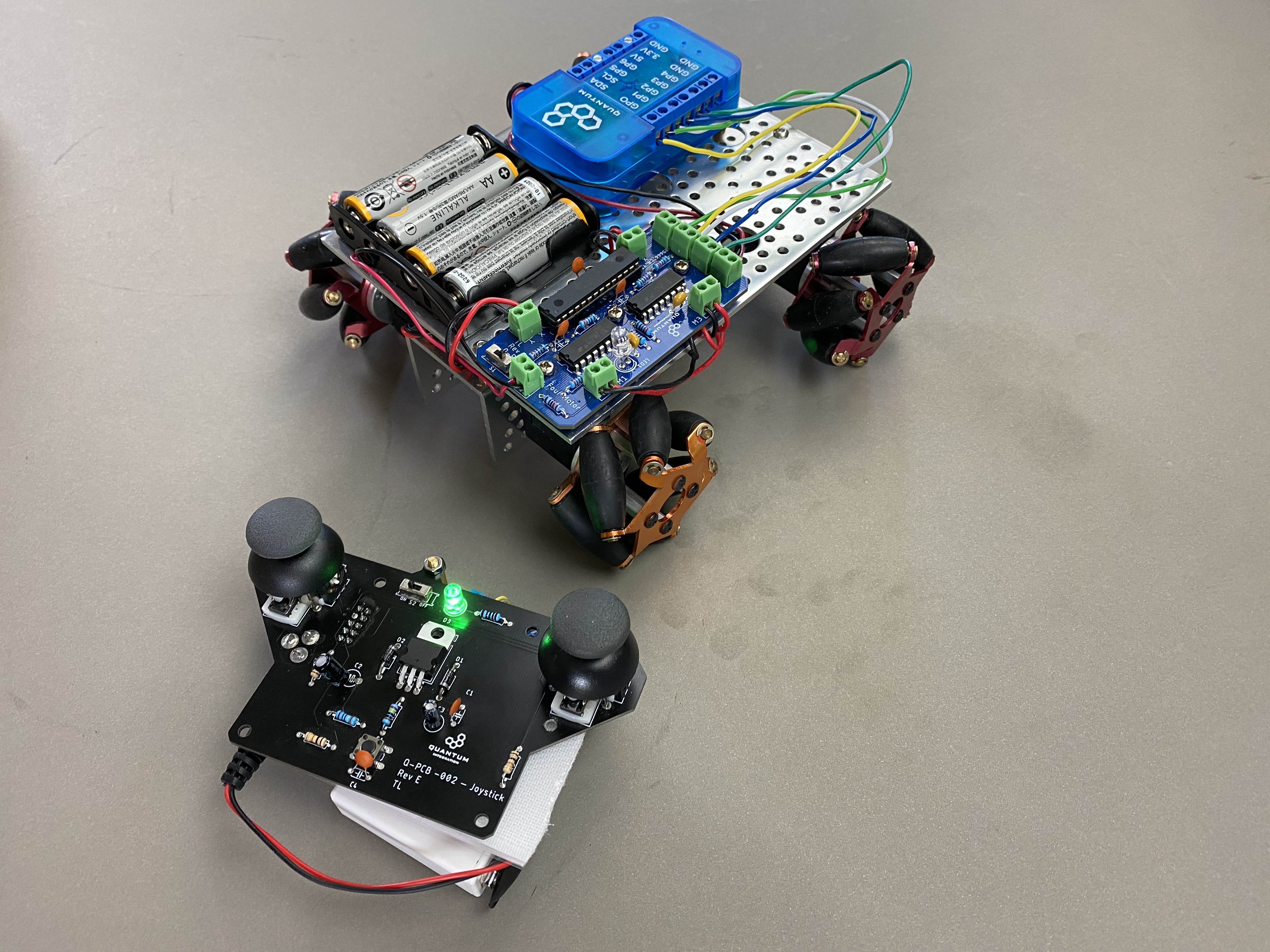
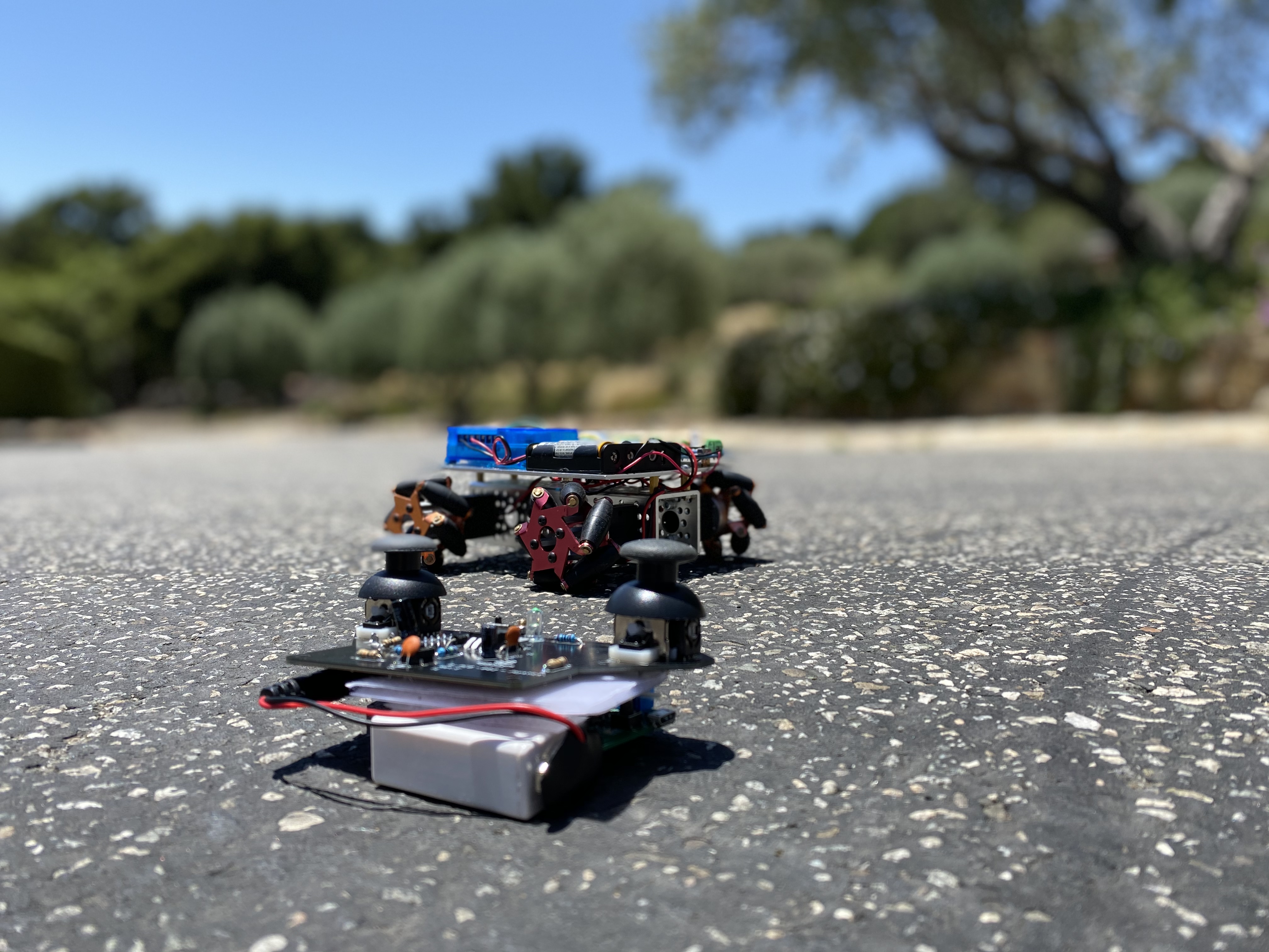
Mecanum Car
The project page can be found here Four Motor Project.
In this section we will explain how to make the DIY Kit compatible with the project.
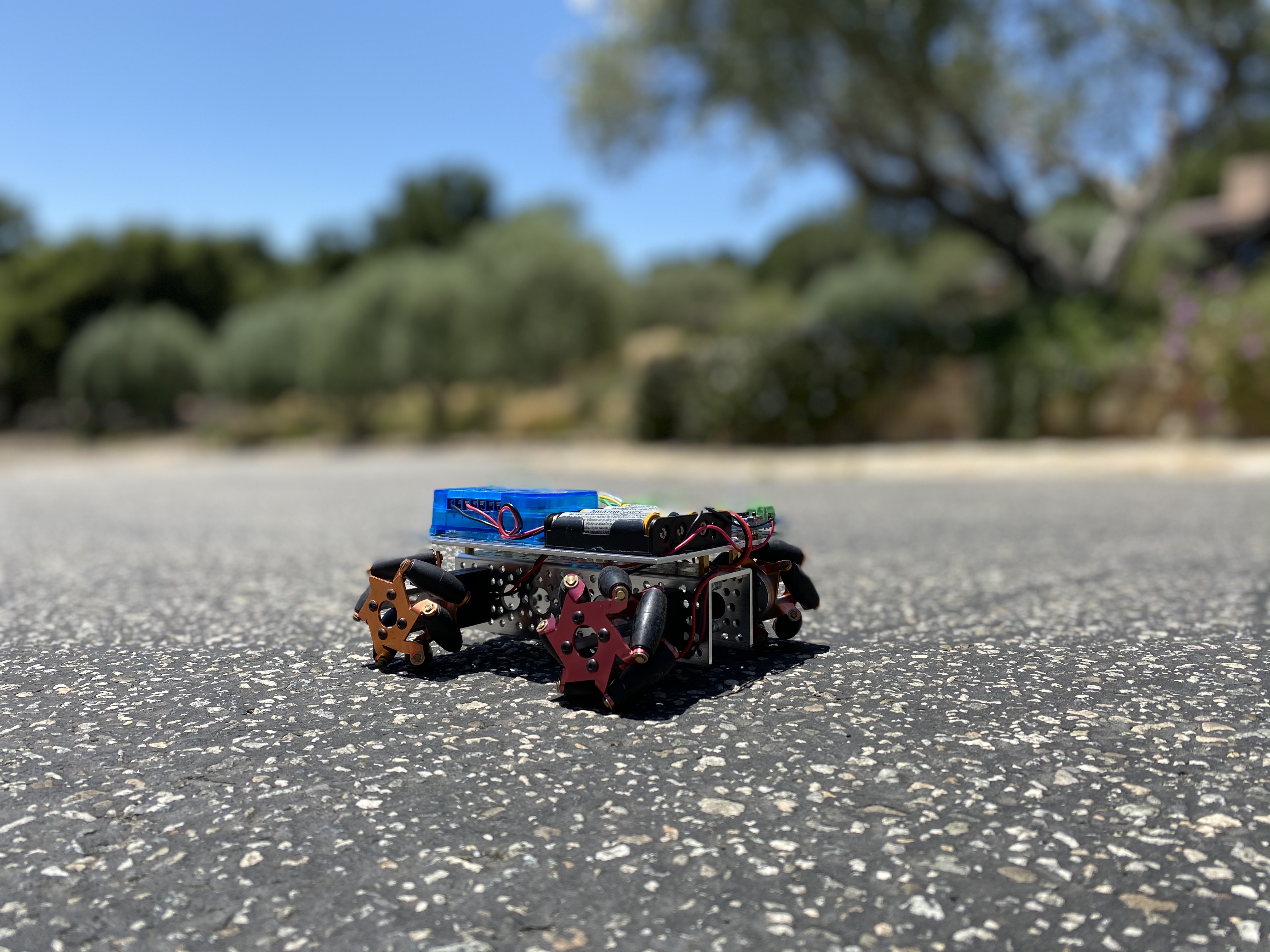
Fist Omnidirectional Mecanum Car
First of all, we need to connect the PCB to the Builder Base. For that we simply connect the Builder Base to connectors the 8 connectors on the left side of the DIY Kit. The labeling of the connectors is identifying the terminals clearly. The connections are exactly the same as in the project. Refer to the section here. The Builder Base can now get powered via USB and power the Kit as well, or get powered through the Kit. For that, the connectors on the right side of the Kit have to be powered with 5V. A switch can interrupt the power in this configuration to save energy if for example a battery is used.Firmware and app are exactly the same! Please refer to the instructions in this section
If you need more specific information about the joystick and the motors use this link Four Motors and this Joystick.
Gallery
Resources
App & Firmware
|
|
This DIY Kit page is currently optimized for revision F.
Current revision
Assembly files for the current revision of the DIY Kit (Rev F): | https://github.com/QuantumIntegration/Q-PCB-003-Four-Motor-Hardware-Files/tree/Rev_F |
|---|
Older revisions
- | - |
|---|