| Table of Contents |
|---|
Introduction
The TLC5940 driver is used in conjunction with the 16-port TLC5940 12-bit pwm expander and a generic H-Bridge to operate different kinds of motors. This setup can drive 8 motors from a single Builder Base.
Driver Parameters
The TLC5940 driver for the TLC5940 chip has seven parameters that need to be configured:
GSCLK
This is the PWM frequency driven by the Builder Base. This pin can be connected to any pin on the Builder Base if pin is not already in use for something else.
XLAT
This is the register clock line which shifts the serial data once transmitted into the output registers which eventually set the pins to the desired output state. This pin can be connected to any pin on the Builder Base if pin is not already in use for something else.
BLANK
This line resets the grayscale clock after counted up to 4095. This pin can be connected to any pin on the Builder Base if pin is not already in use for something else.
SIN
This is the data line which transmits the serial data bits from the client to the extender chip. This pin can be connected to any pin on the Builder Base if pin is not already in use for something else.
SCLK
This is the serial clock line which keeps the transmission of the serial data bits in sync. This pin can be connected to any pin on the Builder Base if pin is not already in use for something else.
DC 1 Pin
This is one channel of the TLC5940 connected to an input pin on the H-Bridge. The pin transmits information regarding speed and direction. Since the TLC is a current sink, we nee 2k pull up resistors on the connection between the dc pin on the H-Bridge and the TLC. Please select a number between 0-15 to connect the channels seen on the pinout.
DC 2 Pin
This is the other channel of the PCA9685 connected to the other input pin on the H-Bridge. The pin transmits information regarding speed and direction as well. Since the TLC is a current sink, we nee 2k pull up resistors on the connection between the dc pin on the H-Bridge and the TLC. Please select a number between 0-15 to connect the channels seen on the pinout.
Wiring
This is a pinout of the DIP version of the chip
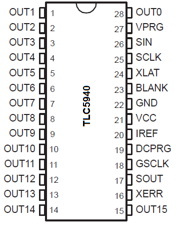
More information regarding the chip can be found in its datasheet
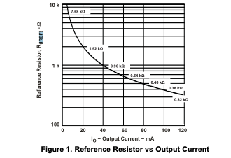
The table regarding current limiting on the IREF pin can be seen here
Example
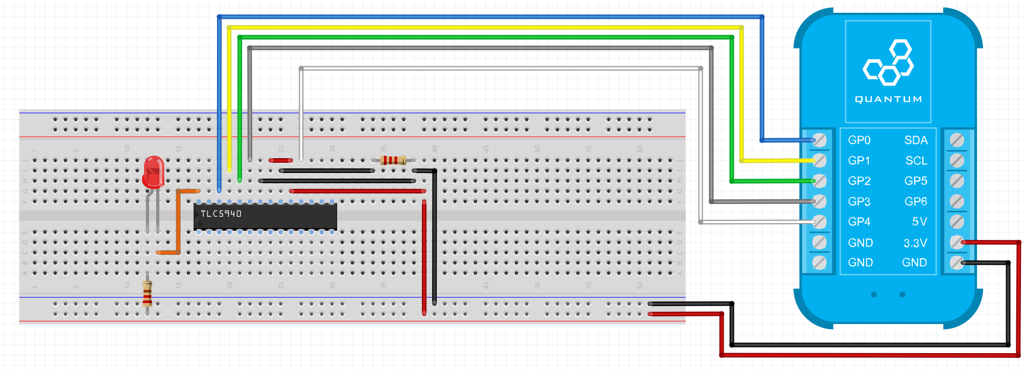
On the TLC5940 the GSLCK, XLAT,BLANK,SIN, and SCKL pins are connected to the Builder Base via the GP0, GP1, GP2 GP3, and GP4 pins respectively. The TLC5940 connects two of its channels to an H-Bridge to control the motor speed and direction. These pins have to be also pulled high via a 2k resistor since the TLC is configured as a current sink. The enable pin of the H-Bridge is tied high in this setup so we can preserve another pin. We also use a 2k resistor on the IREF pin of the TLC to stabilize the current flowing into the TLC.
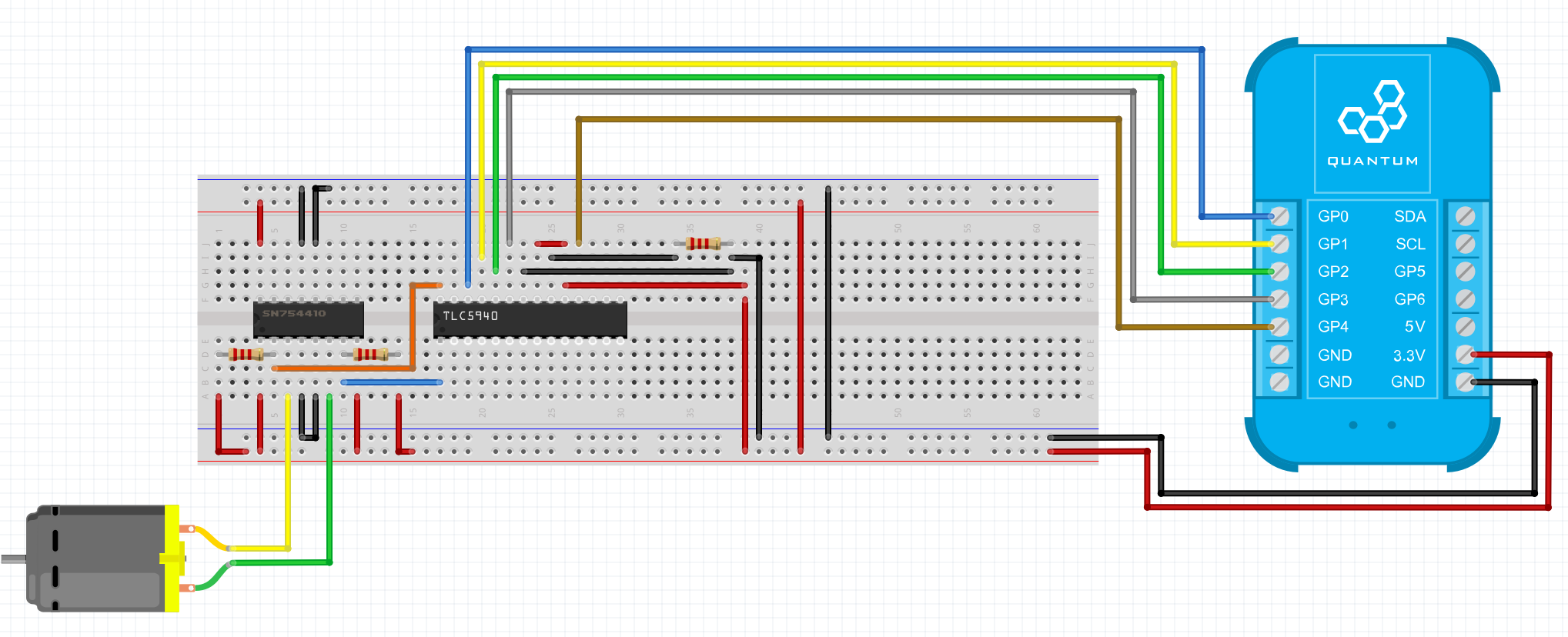
Breadboard
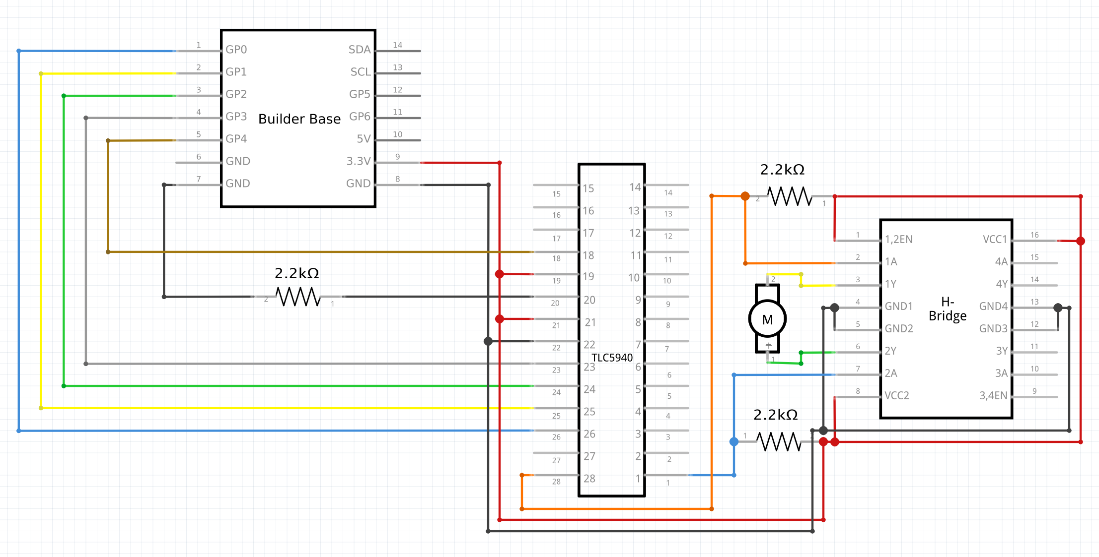
Schematic
Used Pins
Used Pins | Description |
|---|---|
GP4 (can be any GP pin) | Connected to the GSLCK pin |
GP2 (can be any GP pin) | Connected to the XLAT pin |
GP3 (can be any GP pin) | Connected to the BLANK pin |
GP0 (can be any GP pin) | Connected to the SIN pin |
GP1 (can be any GP pin) | Connected to the SCKL pin |
5V | This pin provides the power |
GND | This pin provides the GND |
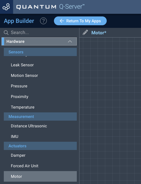
How to write an App
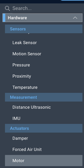
Navigate to the App Builder and create a new application. You can find the “Motor” code object under the “Hardware” Tab in the object drop down menu on the left, or you can also use the search bar.
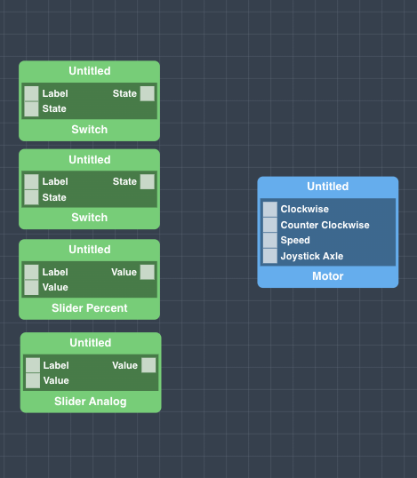
Drag the “Motor” object onto the grid.
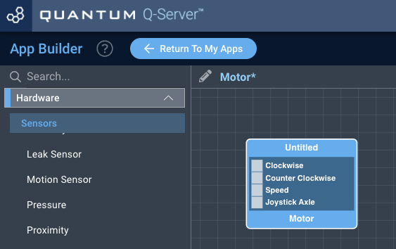
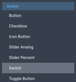
Next, under the interface tab, locate the switch, slider percent, and slider analog interface objects. Next, drag two of the switch objects, a slider percent object, and slider analog object onto the grid.
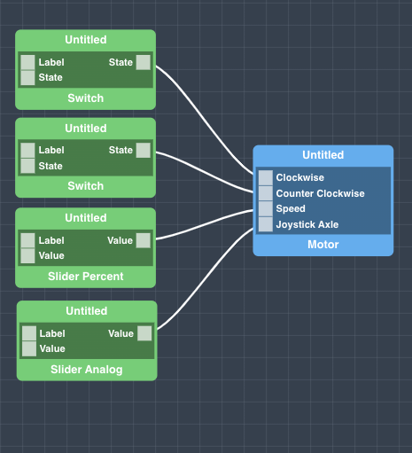
Finally, connect a switch object to each the clockwise and counter clockwise ports on the motor object, connect the slider percent object to the speed port, and the Slider Analog to the Joystick Axle. For the sake of organization, label each of the interface objects, and save your application.
How to create a firmware
Navigate to the Firmware Builder and create a new firmware file.
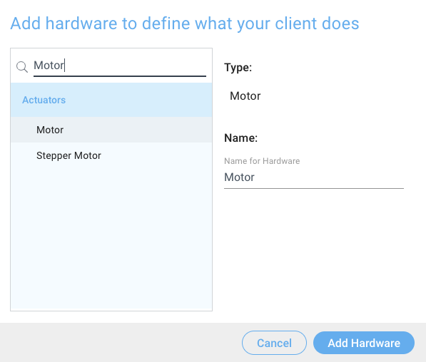
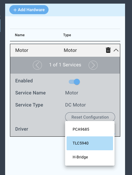
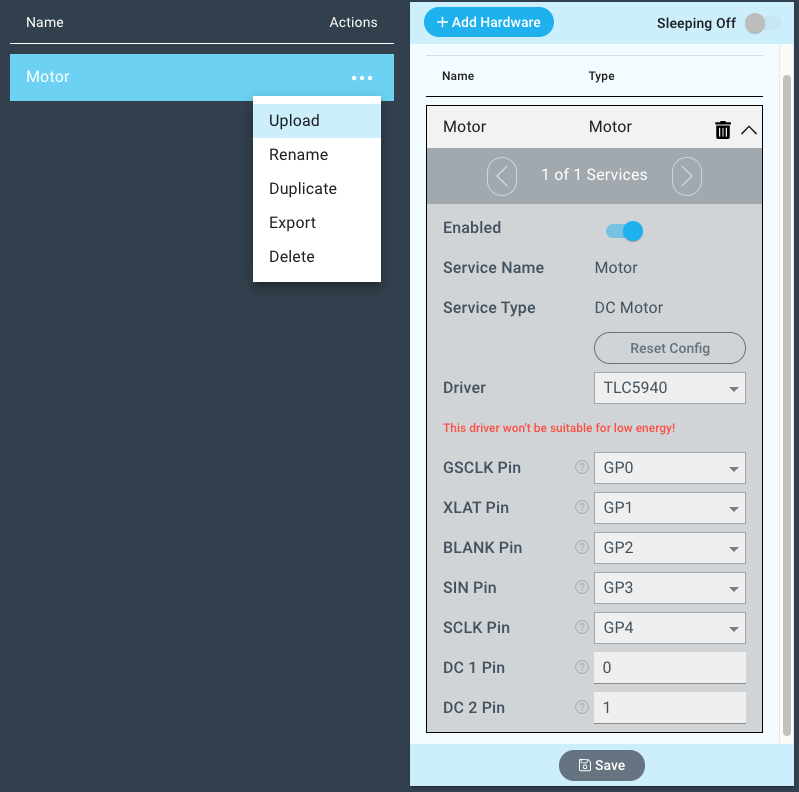
Click the “+ Add Hardware” button and listed under the “Actuators” tab find the “Motor” hardware option.
Give your device a name, and click “Add Device”

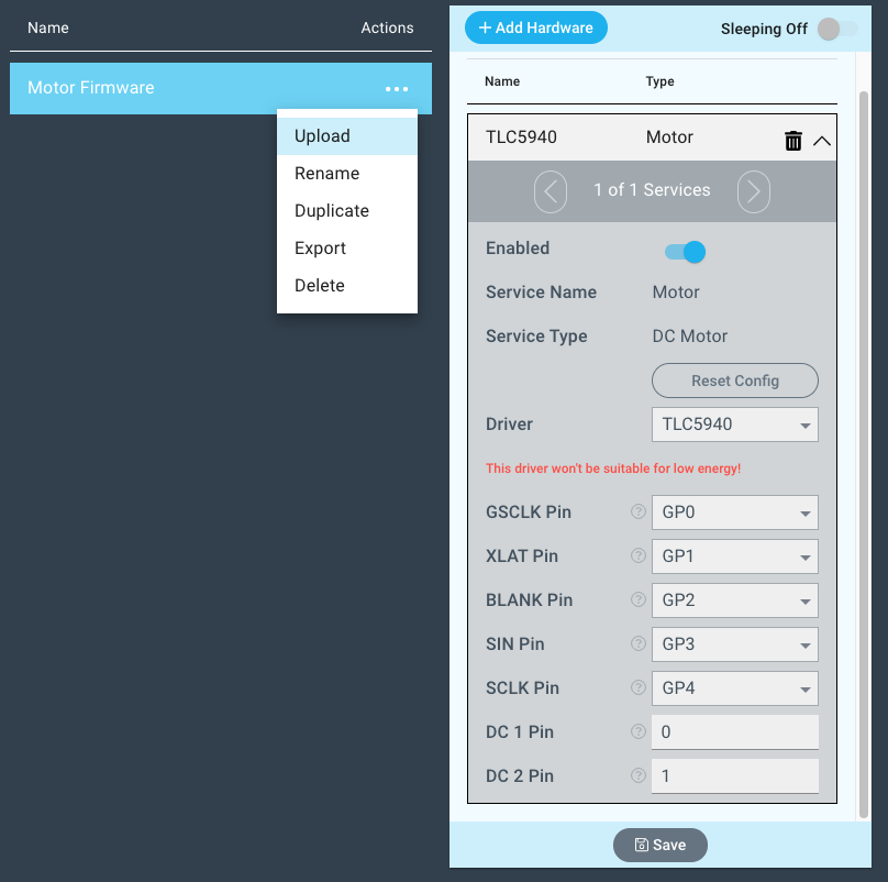
Next, select the “TLC5940” under the driver dropdown menu.
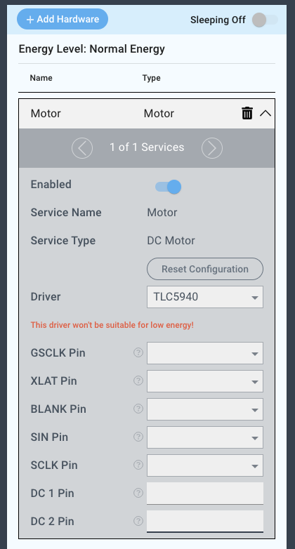
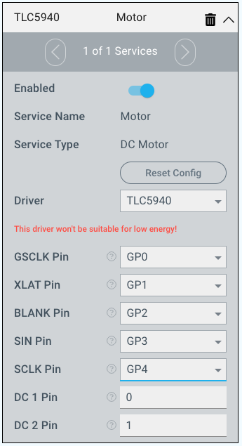
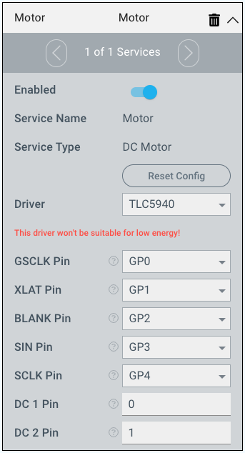
For this example we select:
GSCLK Pin: GP0
XLAT Pin: GP1
BLANK Pin: GP2
SIN Pin: GP3
SCLK Pin: GP4
DC 1 Pin: 0
DC 2 Pin: 1
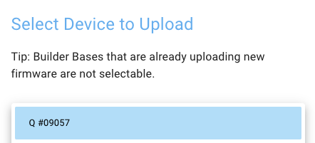
You may now save your firmware file and upload it to one of your clients.
Supported Hardware
TLC5940
Motors
Other Actuators
Downloads
Apps
| View file | ||
|---|---|---|
|
Firmware
| View file | ||
|---|---|---|
|
Assets