| Table of Contents |
|---|
Introduction
The ADS1015 driver for Analog Inputs is used to detect the voltage level of an analog signal on the selected channel on an external ADC (Analog to Digital converter). The selected analog channel gets a granularity assigned which determines at what minimum change the Central Core gets notified.
Driver Parameters
The ADS1015 driver for Analog Inputs has three parameters that have to be configured:
I2C Address
This is the address the device is being referenced by on the I2C bus. The address can be set by connecting the ADDR pin from the chip to one of the following pins corresponding to the following addresses:
I2C Address | Binary Address | Connected Pin |
|---|---|---|
0x48 | 1001000 | GND |
0x49 | 1001001 | VDD |
0x4a | 1001010 | SDA |
0x4b | 1001011 | SCL |
More information about addressing can be found in the datasheet
Channel
This is the channel on the ADS1015 reading the input voltage, just select a channel from the dropdown list.
Granularity
This is the minimum change from the last notifications value that would trigger sending another notification to the Central Core. This helps us to only wake up and notify when the application specific threshold has been passed. Important values:
The Analog In range: 0-4095 (12 bit)
The Granularity range 0-200
Wiring
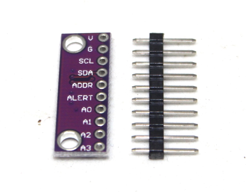
Since the ADS1015 does not come as a DIP version we just assume that we use a breakout board. The actual pinout should be very similar to the one shown
Example
Channel 0 is connected to a potentiometer which acts as a voltage divider in this case. The resistance does not really matter unless it is in the higher range (>10000Ω) to keep the current flow low. The chip is connected to address 0x48 of the I2C bus because by default the ADDR pin is connected to GND.
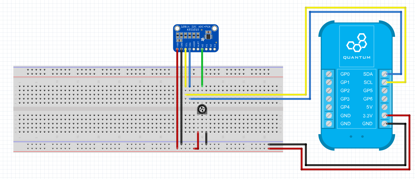
Breadboard
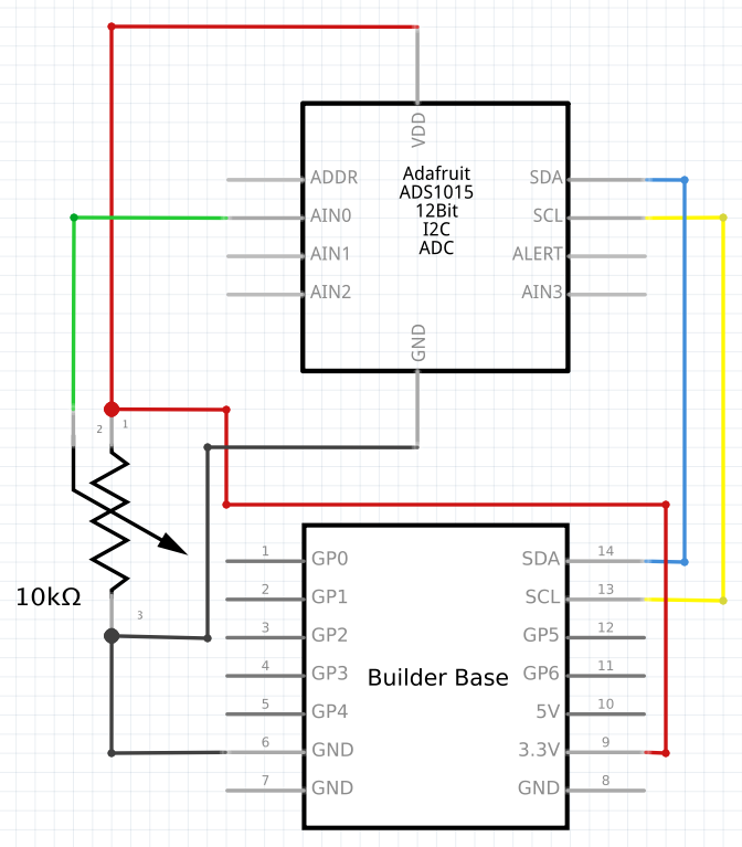
Schematic
Used Pins
Used Pins | Description |
|---|---|
3V3 | The voltage level for the assembly |
GND | The ground potential for the assembly |
SDA | The I2C data line |
SCL | The I2C clock line |
How to write an App
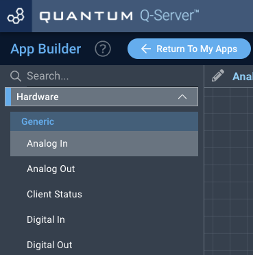
Navigate to the App Builder and create a new application. You can find the “Analog In” code object under the “Hardware” Tab in the object drop down menu on the left, or you can also use the search bar.
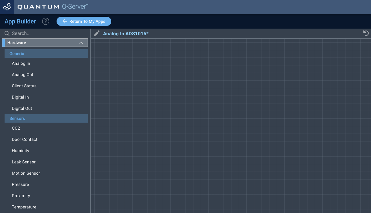
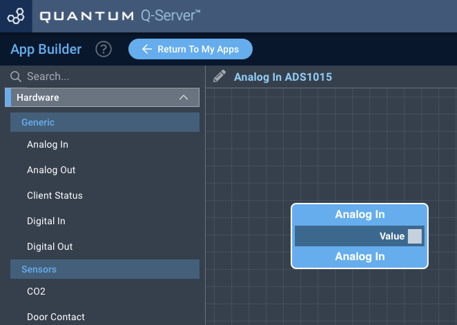
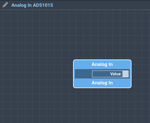
Drag the “Analog In” Object onto the canvas.
Next, locate the “Text” Object under the “Interface” tab and drag it onto the canvas.
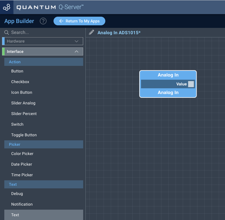
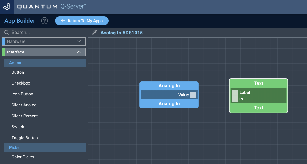
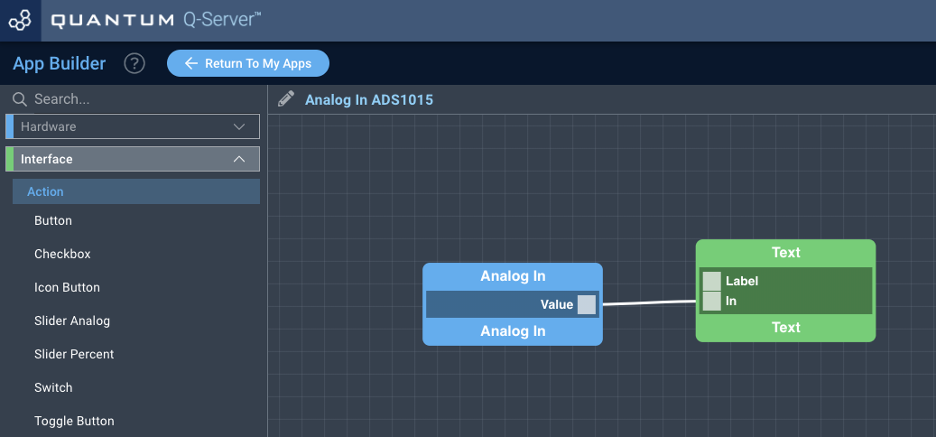
Finally, connect the “State” port from the Digital In Object to the “In” port on the Text Object, and save your application.
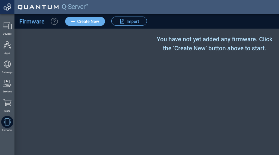
How to create a firmware
Navigate to the Firmware Builder and create a new firmware file.
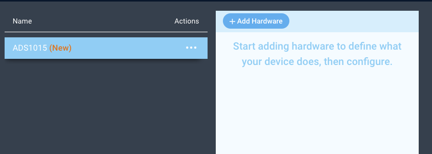
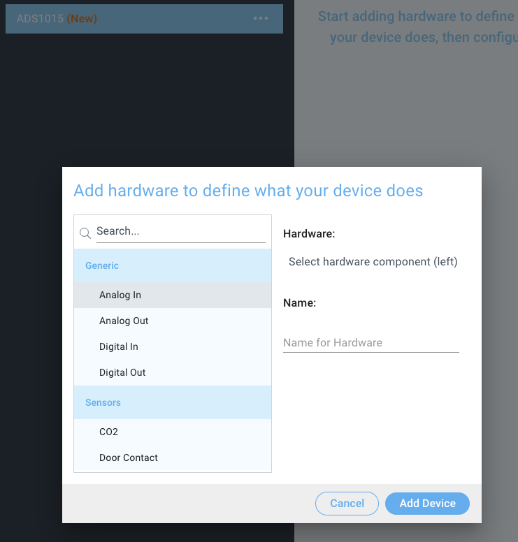
Click the “+ Add Hardware” button which will open a modal window. Scroll down in the list to find the “Generic” section and select the “Analog In” hardware option.
Give your device a name, and click “Add Device”
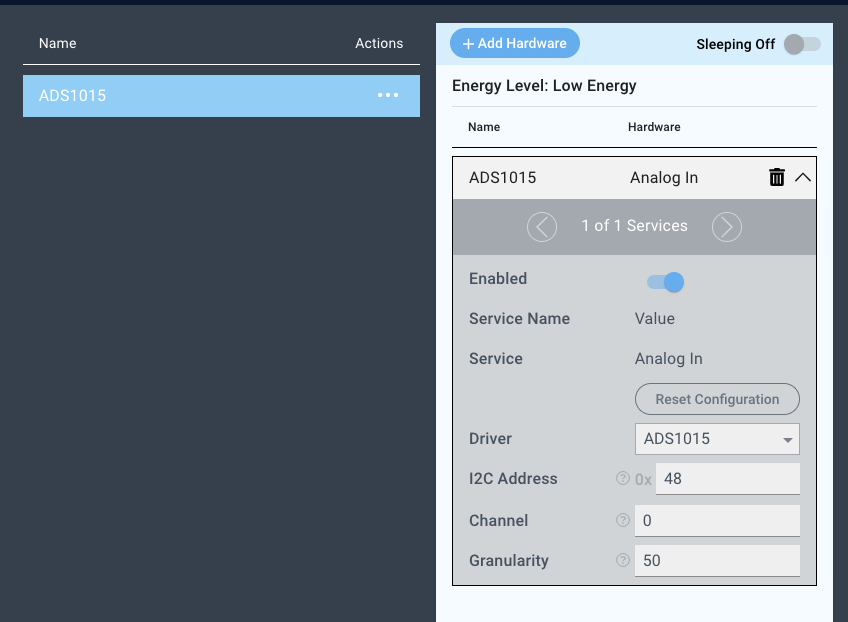
Next, select the “GPIO” driver under the driver dropdown menu, set the Address, the Channel and the Granularity.
For this example we select:
I2C Address: 0x48
Channel: 0
Granularity: 50
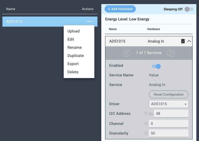
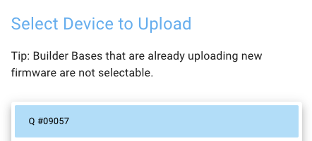
You may now save your firmware file and upload it to one of your Builder Bases.
Supported Hardware
Joysticks
potentiometers
Mostly any analog device
Downloads
Apps
| View file | ||
|---|---|---|
|
Firmware
| View file | ||
|---|---|---|
|
Assets