| Table of Contents |
|---|
Introduction
The 74HC595 driver for Digital Outputs is used to set the digital level of a selected channel on an external GPIO extender. The selected channel includes an optional initial value.
Driver Parameters
The 74HC595 driver for Digital Inputs has five parameters that have to be configured:
DS
This is the data line which transmits the serial data bits from the client to the extender chip. This pin can be connected to any pin on the Builder Base if not already in use
RSCLK
This is the serial clock line which keeps the transmission of the serial data bits in sync. This pin can be connected to any pin on the Builder Base if not already in use
RCLK
This is the register clock line which shifts the serial data once transmitted into the output registers which eventually set the pins to the desired output state. This pin can be connected to any pin on the Builder Base if not already in use
More information regarding the functionality of this device can be found in its datasheet
Channel
The channel is the port/pin combination on the chip. Just select from the dropdown list what channel your project connects to
Mode
This is the initial output mode of the channel
Possible Configurations
High: The channel has a logic level of 1 at initialization
Low: The channel has a logic level of 0 at initialization
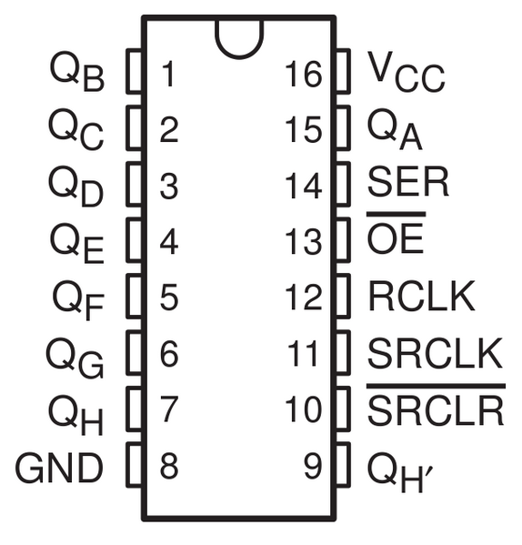
Wiring
This is the pinout of the 74HC595 where Q is the output with its corresponding letter
Example
The channel QA is connected to the LED directly through a current limiting resistor.

Breadboard
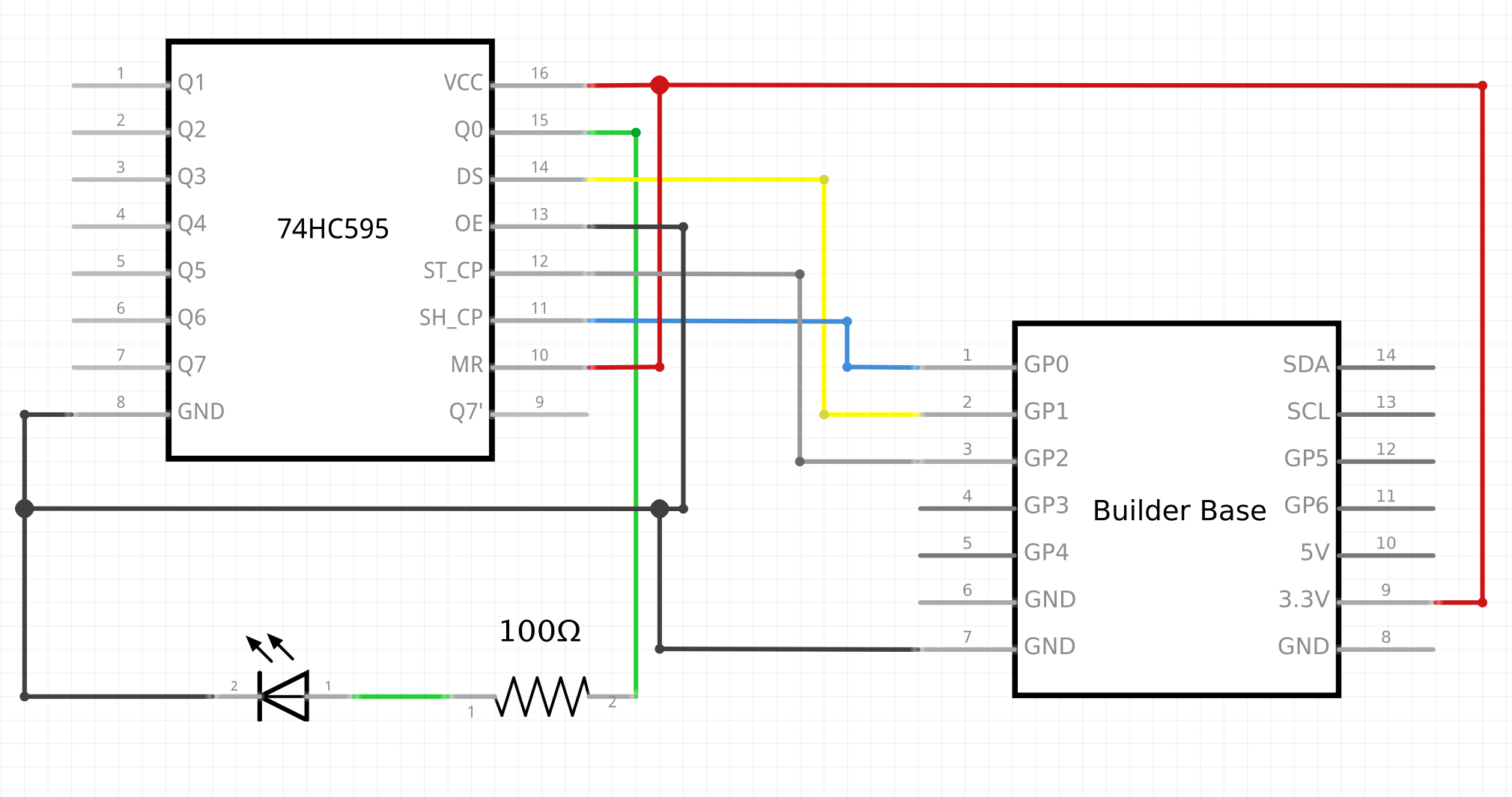
Schematic
Used Pins
Used Pins | Description |
|---|---|
3V3 | The voltage level for the assembly |
GND | The ground potential for the assembly |
GP1 (can be any GP pin) | The DS line |
GP0 (can be any GP pin) | The RSCLK line |
GP2 (can be any GP pin) | The RCLK line |
How to write an App
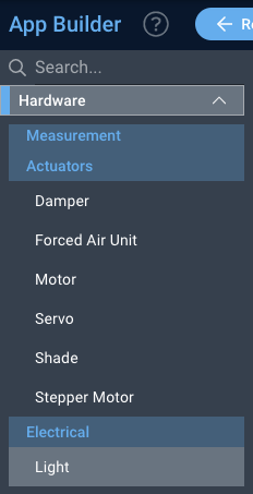
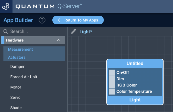
Navigate to the App Builder and create a new application. You can find the “Light” code object under the “Hardware” Tab in the object drop down menu on the left, or you can also use the search bar.
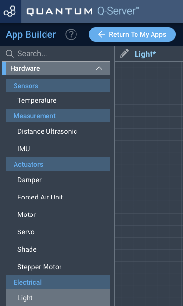
Drag the “Light” object onto the canvas.
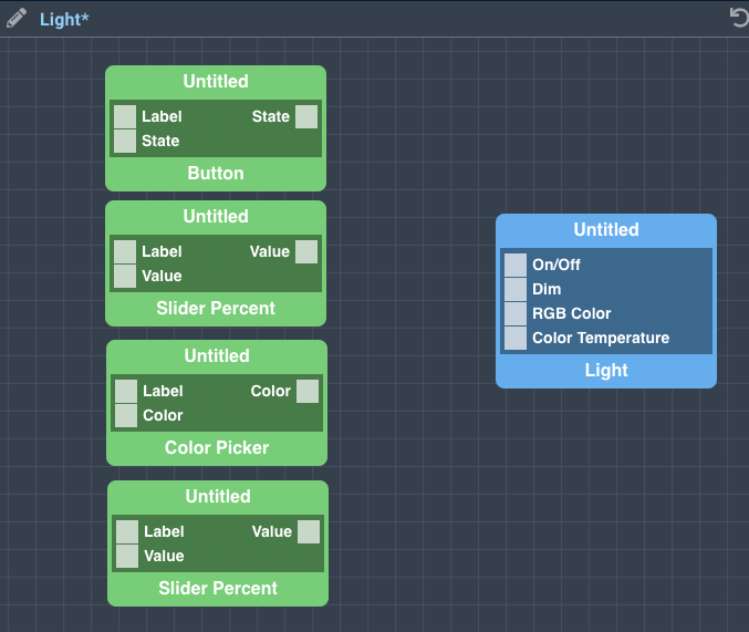
Next, located under the interface tab, drag a button, two slider percent, and one color picker objects onto the grid.
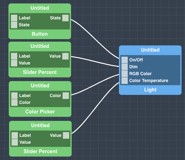
Finally, connect the button object to the on/off port, the slider percent object to the dim port, the color picker to the RGB color port, and the other slider percent object to the color temperature port.
How to create a firmware
Navigate to the Firmware Builder and create a new firmware file.
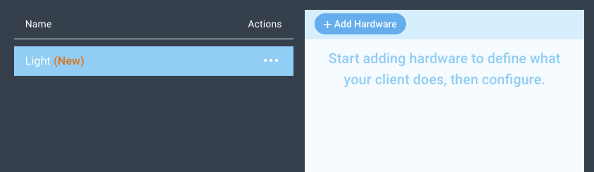
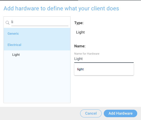
Click the “+ Add Hardware” button which will open a modal window. Scroll down in the list to find the “Electrical” section and select the “Light” hardware option.
Give your device a name, and click “Add Hardware”
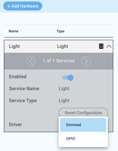
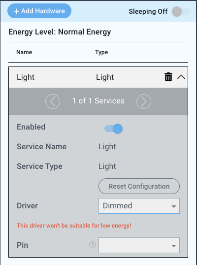
Next, select the “Dimmed” driver under the driver dropdown menu.
For this example we select:
Pin: GP0
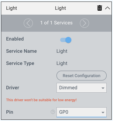
You may now save your firmware file and upload it to one of your clients.

Supported Hardware
LEDs
Most anything that can receive a digital signal
Downloads
Apps
| View file | ||
|---|---|---|
|
Firmware
| View file | ||
|---|---|---|
|
Assets
