| Table of Contents |
|---|
Introduction
The HC-SR04 driver for distance measurement is used in conjunction with the HC-SR04 sensor to measure the distance between itself and an object placed in front of the ultrasonic transducers. The HC-SR04 measures distances between 5 and 300cm, it does this by utilizing its ultrasonic transducers as transmitter and receiver. An ultrasonic sound is beamed from the transmitter and depending on the time it takes for the sound to rebound from the object and carry back to the receiver a distance can be calculated. The HC-SR04 has four pins: GND, power, echo, and trigger.
Driver Parameters
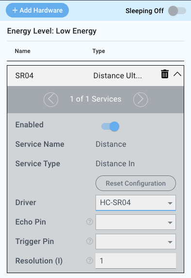
The HC-SR04 driver for the HC-SR04 measurement sensor has three parameters that needs to be configured:
Echo Pin
This is the pin that receives the pinged signal.
Trigger Pin
This pin triggers the HC-SR04 to take a measurement sample.
Resolution(in.)/(cm)
The resolution depends on the measurement system of the central core. If set to imperial, the resolution is in inches and in metric it is in centimeters.
The resolution in imperial ranges from 0 to 11 inches with a default value of 1.
The resolution in metric is ranging from 0 to 30 centimeters with a default value of 1.
For example in the metric system, if our latest reading was 8cm and the resolution is set to 3cm, the builder base is not going to notify the central core unless the value is <5 or >11
Wiring
Example
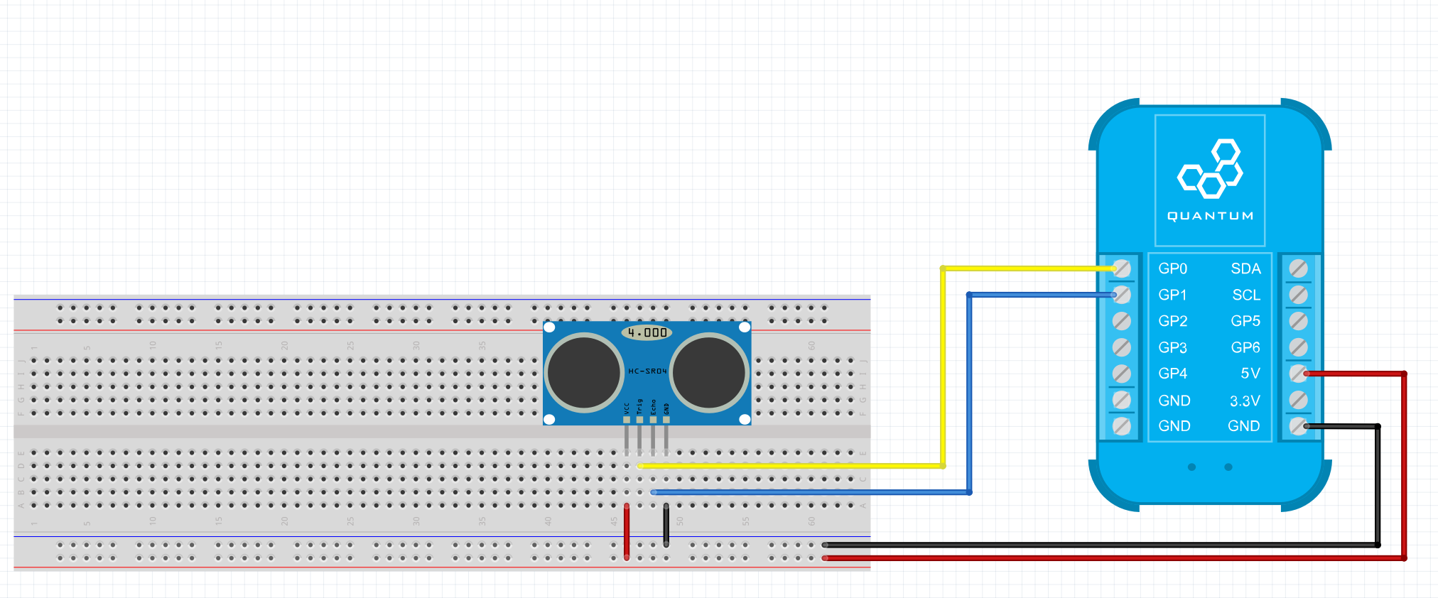
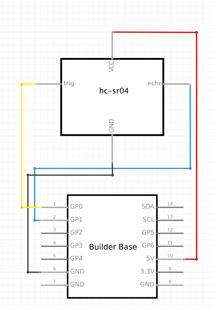
On the HC-SR04 sensor the GP0 pin is connected to Echo Pin and the GP1 Pin is connected to the Trigger Pin, the 5V and GND pins on the Builder Base are then connected to the VCC and GND pins on the HC-SR04 sensor.
Breadboard
Schematic
Used Pins
Used Pins | Description |
|---|---|
GP0 (can be any GP pin) | This pin triggers readings from the HC-SR04 |
GP1 (can be any GP pin) | This pin reads the echo data from the HC-SR04 |
5V | This pin provides the power |
GND | This pin provides the GND |
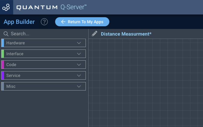
How to write an App
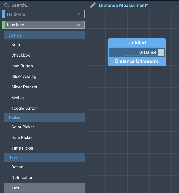
Navigate to the App Builder and create a new application. You can find the “Distance Ultrasonic” code object under the “Hardware” Tab in the object drop down menu on the left, or you can also use the search bar.
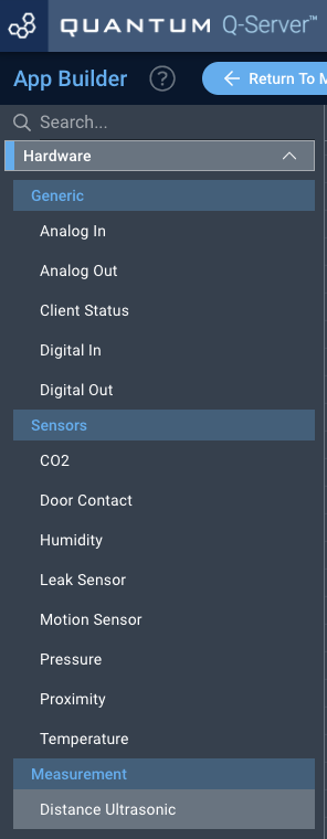
Drag the “Distance Ultrasonic” Object onto the grid.

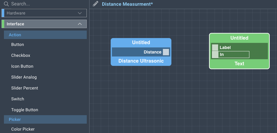
Next, locate the “Text” Object under the Interface tab and drag it onto the grid.
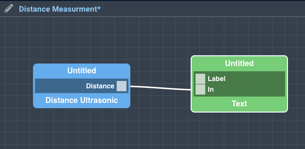
Finally, connect the “Distance” port from the Motion Sensor Object block to the “State” port on the Switch block and save your application.
How to create a firmware
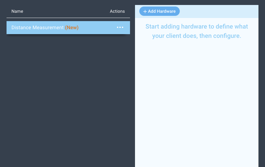
Navigate to the Firmware Builder and create a new firmware file.
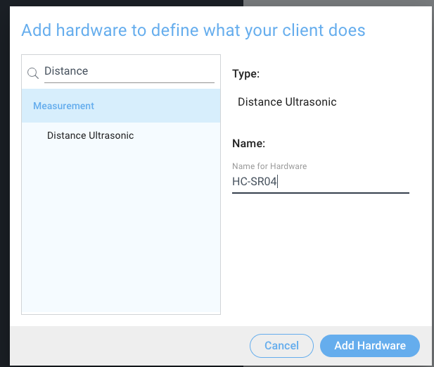
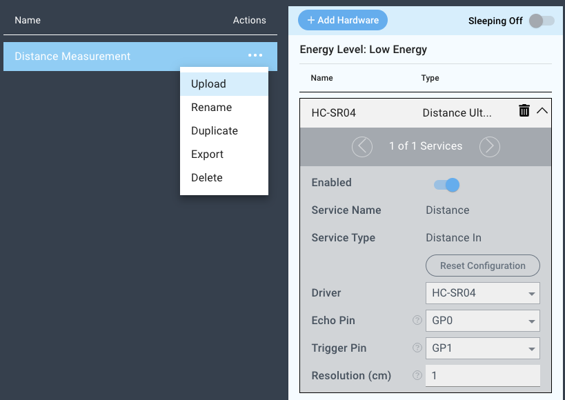
Click the “+ Add Hardware” button and listed under the “Sensors” tab find the “Distance Measurement” hardware option.
Give your device a name, and click “Add Device”
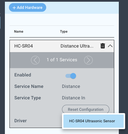
Next, select the “HC-SR501” driver under the driver dropdown menu.
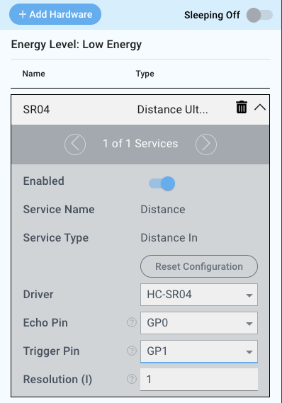
For this example we select:
Echo Pin: GP0
Trigger Pin: GP1
Resolution(I): 1
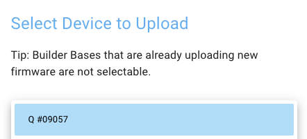
You may now save your firmware file and upload it to one of your clients.
Supported Hardware
HC-SR04
Downloads
Apps
| View file | ||
|---|---|---|
|
Firmware
| View file | ||
|---|---|---|
|
Assets