| Table of Contents |
|---|
Introduction
The 28BYJ-48 driver is designed to work specifically with the 28BYJ-48 stepper motor. I is a special unipolar stepper motor and a darlington transistor driver or any circuitry that amplifies the current of the output pins. is used to drive it. The signals from the Builder Base are what the motor requires but transistor driver is needed to provide enough current to the coils in the stepper motor. We need four channels of the driver, a typical one would be the ULN2003. Usually this motor ships with a little driver PCB featuring this iC. The motor has a preset steps per revolution of 2048 offering a big amount of precision this way.
Driver Parameters
The Generic Step Direction driver has six parameters that need to be configured:
Pin 1
This pin is connected to the first coil
Pin 2
This pin is connected to the second coil
Pin 3
This pin is connected to the third coil
Pin 4
This pin is connected to the fourth coil
RPM
This is the revolutions the motor performs per minute. We can handle revolutions per minute between 5 and 60 with the default being 10.
Wiring
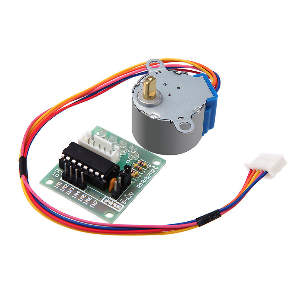
The included driver PCB offers a plug to directly connect the motor and easily connectable signal and power pins.
Example
In this example we use a UNL2003 driver IC to control the 28BYJ-48 stepper motor. From the Builder Base we have the GP0, GP1, GP2, and GP3 pins connected to the IN 1 - 4 pins on the UNL2003 respectively. We then have the OUT 1 , 2 , 3 , and 4 pins connected to the Orange, Yellow, Pink, and Blue pins respectively on the stepper motor. Both the COM and 5V pins on the chip and builder base are connected to the Red pin on the stepper motor. This setup mirrors the connections of the driver PCB. In this case we are not using an external power supply since the 28BYJ-48 works with 5V that can be sourced from the Builder Base.
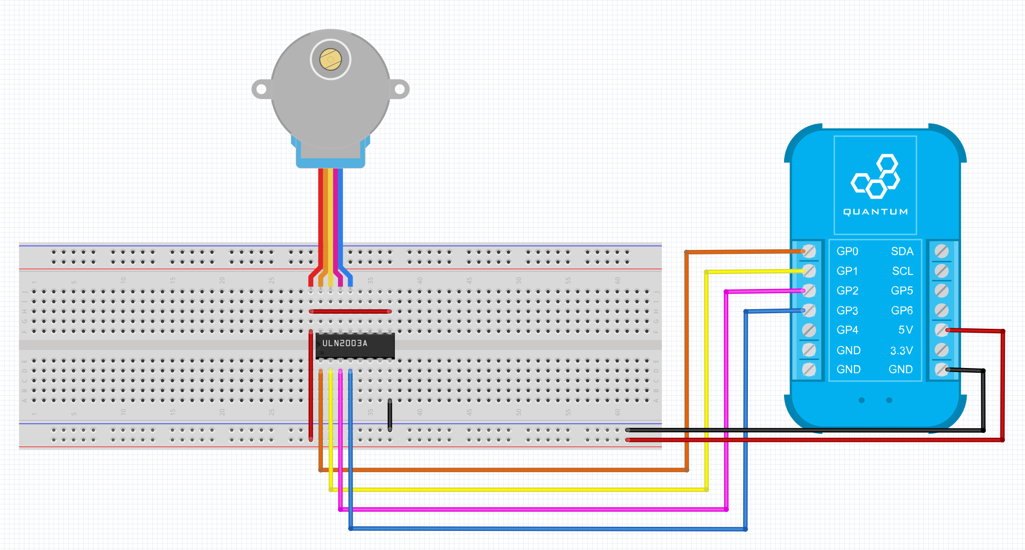
Breadboard
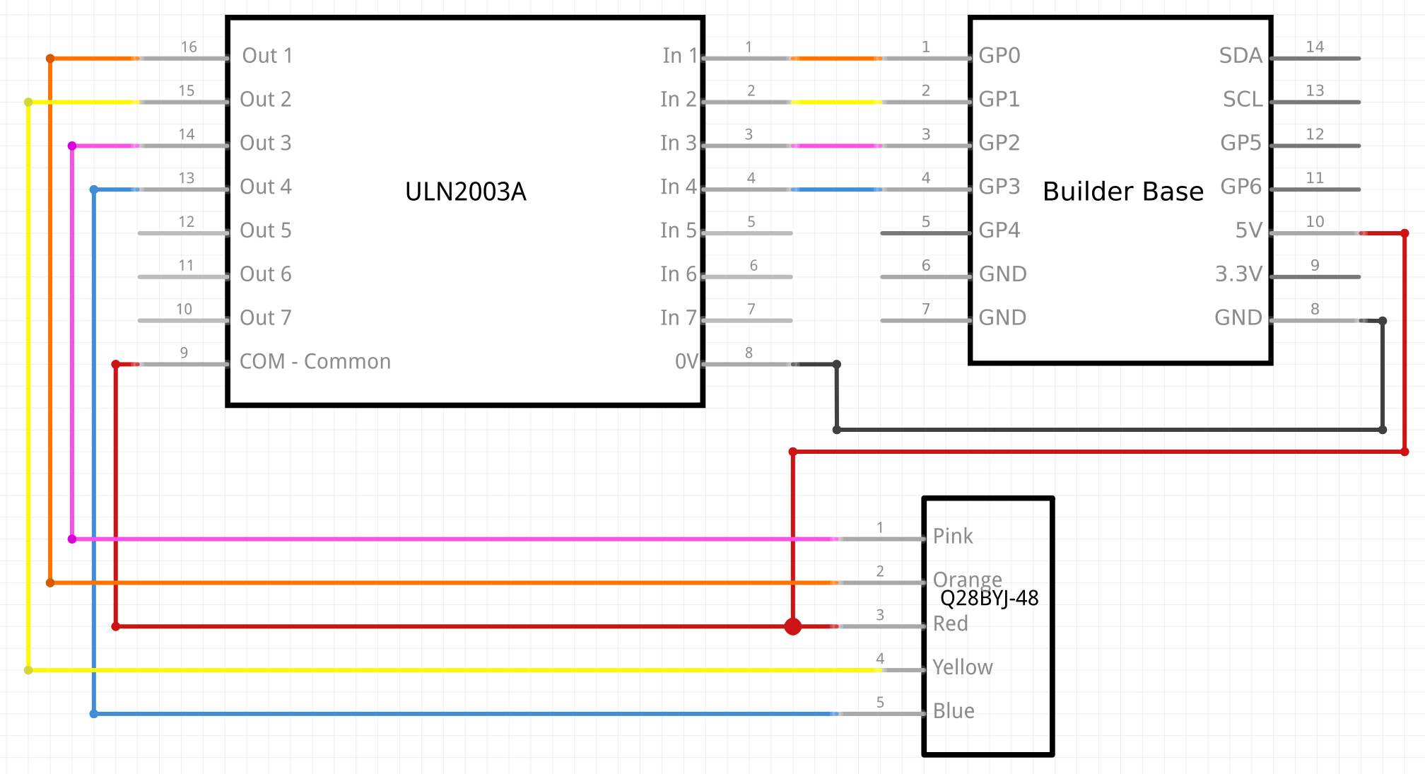
Schematic
Used Pins
Used Pins | Description |
|---|---|
GP0: (Can be any GP pin) | IN 1 |
GP1: (Can be any GP pin) | IN 2 |
GP2: (Can be any GP pin) | IN 3 |
GP3: (Can be any GP pin) | IN 4 |
5V: | Common 5V power for the IC and Stepper Motor |
GND: | Provides grounding for the circuit: Connected to GND pin on the IC. |
How to write an App
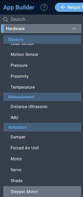
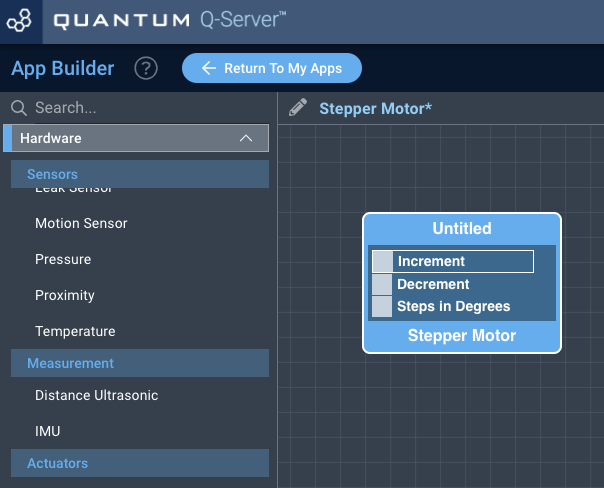
Navigate to the App Builder and create a new application. You can find the “Stepper Motor” code object under the “Hardware” Tab in the object drop down menu on the left, or you can also use the search bar.
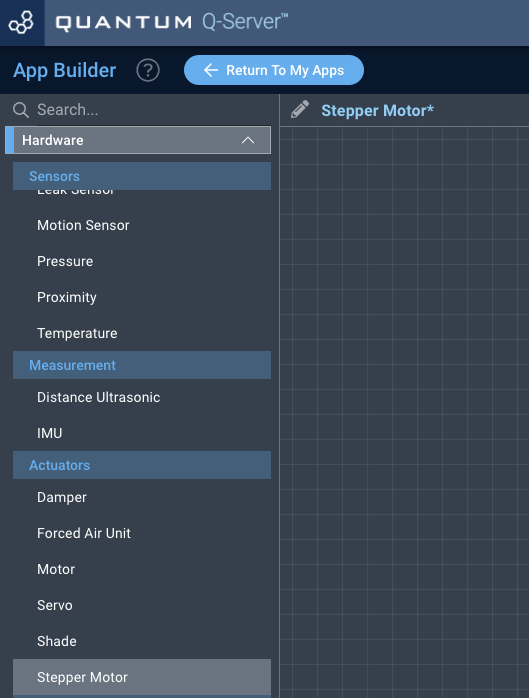
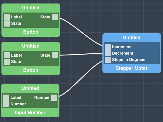
Drag the “Stepper Motor” Object onto the canvas.
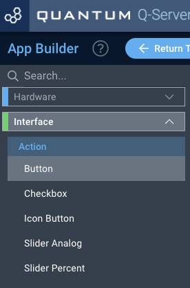
Next, locate the “Button” and “Input Number” Objects under the interface tab and drag two instances of the “Button” Object and one instance of the “Input Number” Object onto the canvas.
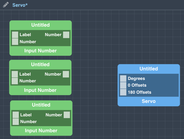
Finally, from the “Button” Objects connect one state port to the Increment port and one state port to the Decrement port on the “Stepper Motor” Object. From the “Input Number” Object connect the Number port to the Steps in Degrees port. If you wish, label your code objects for easier identification on the dashboard, and save your application.
How to create a firmware
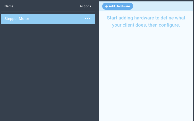
Navigate to the Firmware Builder and create a new firmware file.
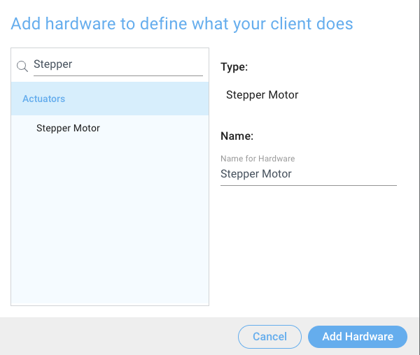
Click the “+ Add Hardware” button which will open a modal window. Scroll down in the list to find the “Generic” section and select the “Stepper Motor” hardware option.
Give your device a name, and click “Add Device”
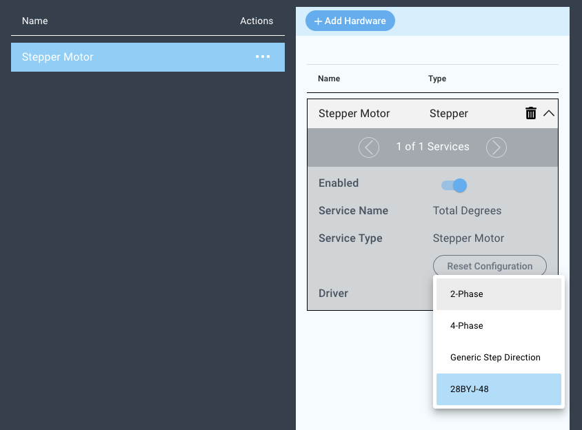
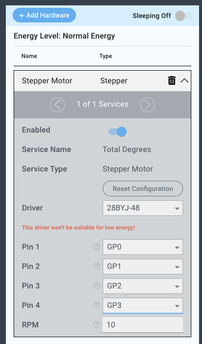
Next, select the “2-Phase ” driver under the driver dropdown menu.
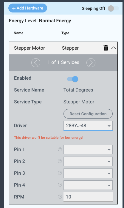
For this example we select:
Pin 1: GP0
Pin 2: GP1
Pin 3: GP2
Pin 4: GP3
RPM: 10
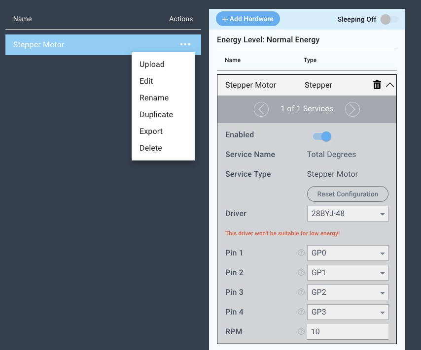
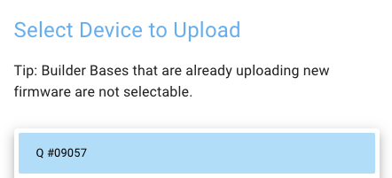
You may now save your firmware file and upload it to one of your clients.
Supported Hardware
28BYJ-48 Stepper Motor
Downloads
Apps
| View file | ||
|---|---|---|
|
Firmware
| View file | ||
|---|---|---|
|
Assets