| Table of Contents |
|---|
Introduction
The HD44789 driver for LCDs drives a classic 2x16 display with HD44789 chipset via 6 pins of the Builder Base. The display has separate backlight pins which can be used to light up the background of the display. It also has a pin to connect a contrast resistor, the easiest way here to adjust the right value is to use a potentiometer.
Driver Parameters
The HD44789 driver for LCDs has six parameters that need to be configured:
RS
This pin determines whether a command or a character is written currently.
E
This pin enables a sent command and latches it in.
D4
The first bit of the four data bit lines.
D5
The second bit of the four data bit lines.
D6
The third bit of the four data bit lines.
D7
The fourth bit of the four data bit lines.
Wiring
Example
Pins GP0 and GP1 are connected to the RS and EN pins on the display. The data is transmitted via pins GP2-GP5 which are connected to pins D4-D7 on the display. The display and its backlight are separately powered from the GND and 5V pins as well as the two inputs of the potentiometer for the contrast.
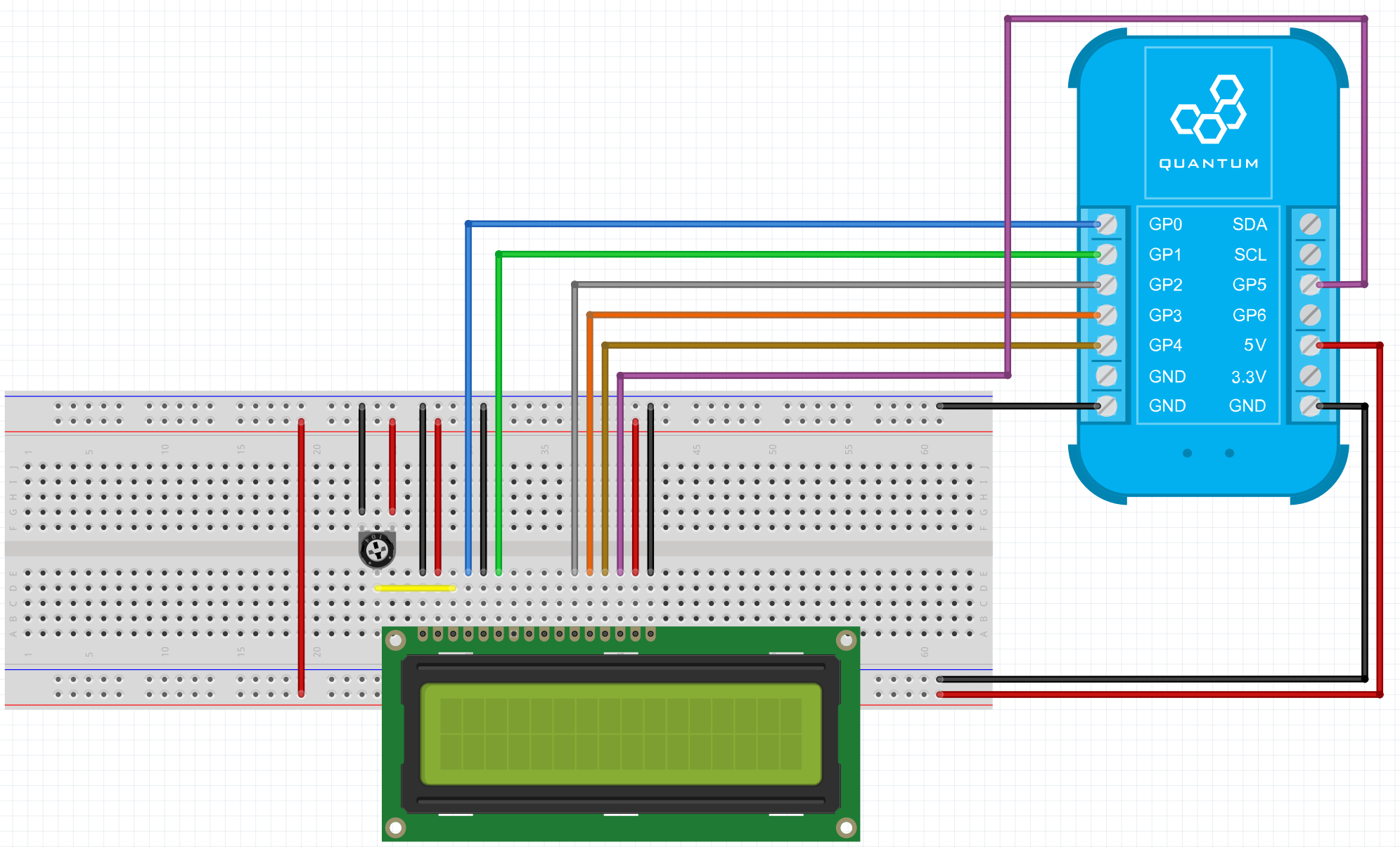
Breadboard
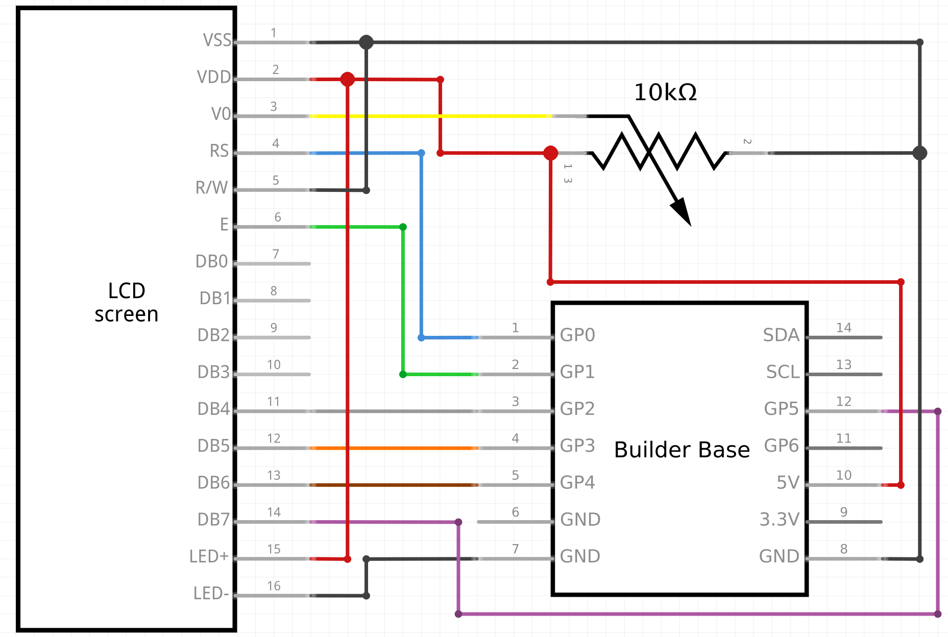
Schematic
Used Pins
Used Pins | Description |
|---|---|
GP0 (can be any GP pin) | This pin is connected to the RS pin on the display |
GP1 (can be any GP pin) | This pin is connected to the EN pin on the display |
GP2 (can be any GP pin) | This pin is connected to the D4 pin on the display |
GP3 (can be any GP pin) | This pin is connected to the D5 pin on the display |
GP4 (can be any GP pin) | This pin is connected to the D6 pin on the display |
GP5 (can be any GP pin) | This pin is connected to the D7 pin on the display |
5V | provides power to display and backlight |
GND | provides GND to display and backlight |
How to write an App
Navigate to the App Builder and create a new application. You can find the “LCD” code object under the “Hardware” Tab in the object drop down menu on the left, or you can also use the search bar.
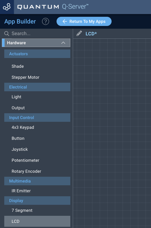
Drag the “7-Segment” object onto the canvas.
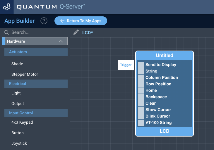
Next, located under the interface tab find the “Button” and “Input Text” objects, and drag two “Button” objects and one “Input Text” object onto the canvas.
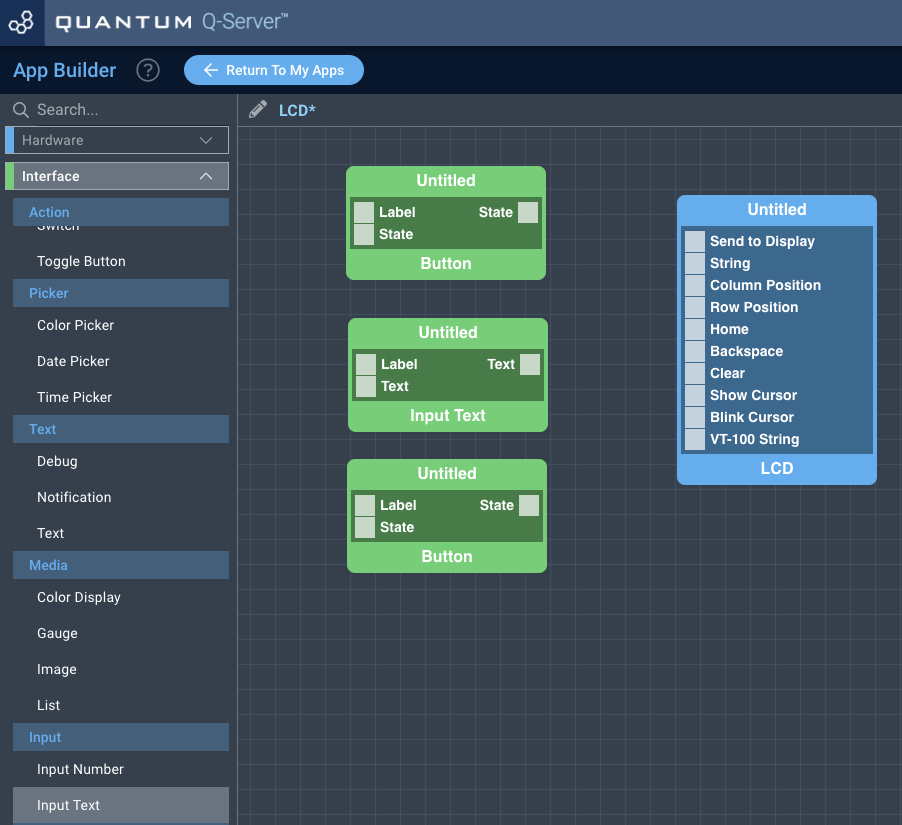
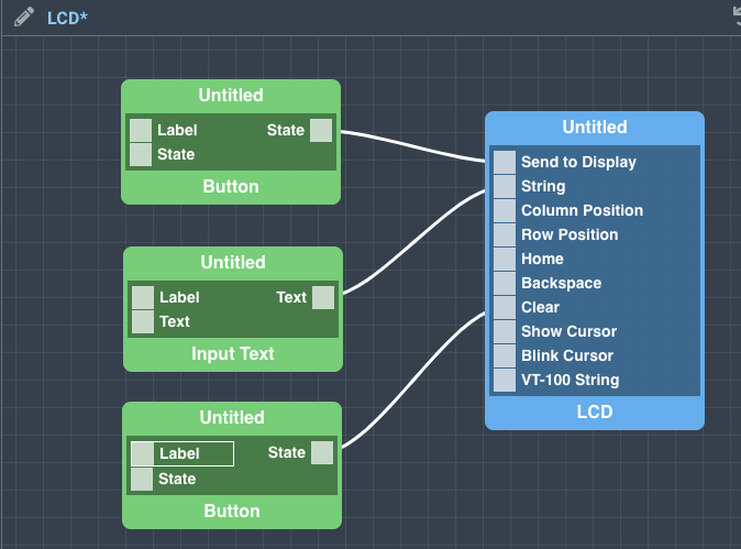
Finally, connect Text port form the “Input Text” object to the String port on the “LCD” object. Next, connect a State port from one of the “Button” objects to the Send to Display port on the LCD object, and connect the State port from the other “Button” object to the Clear port on the “LCD” object.
Finally, you may label your objects and save your application.
How to create a firmware
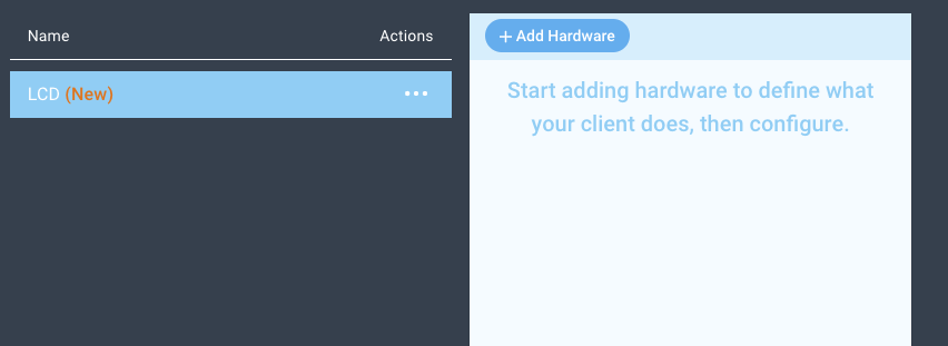
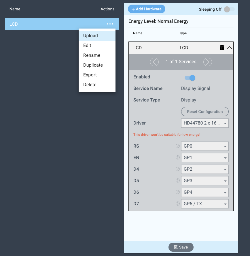
Navigate to the Firmware Builder and create a new firmware file.
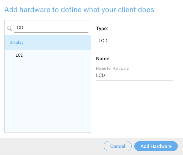
Click the “+ Add Hardware” button which will open a modal window. Scroll down in the list to find the “Display” section and select the “LCD” hardware option.
Give your device a name, and click “Add Hardware”
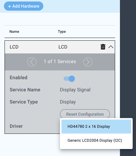
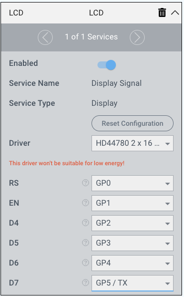
Next, select the “HD44780 2 x 16 Display” driver under the driver dropdown menu.
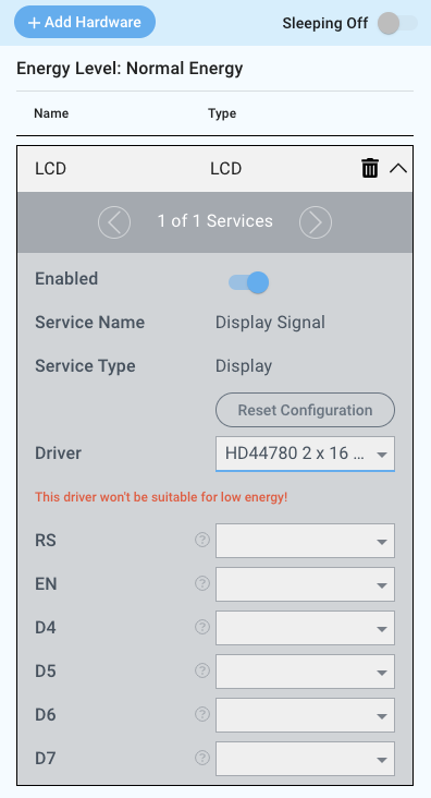
For this example we select:
RS: GP0
EN: GP1
D4: GP2
D5: GP3
D6: GP4
D7: GP5/TX
You may now save your firmware file and upload it to one of your clients.
Supported Hardware
HD44780 2x16 LCD Display
Downloads
Apps
| View file | ||
|---|---|---|
|
Firmware
| View file | ||
|---|---|---|
|
Assets