| Table of Contents | ||||
|---|---|---|---|---|
|
Overview
| Widget Connector | ||||||||||
|---|---|---|---|---|---|---|---|---|---|---|
|
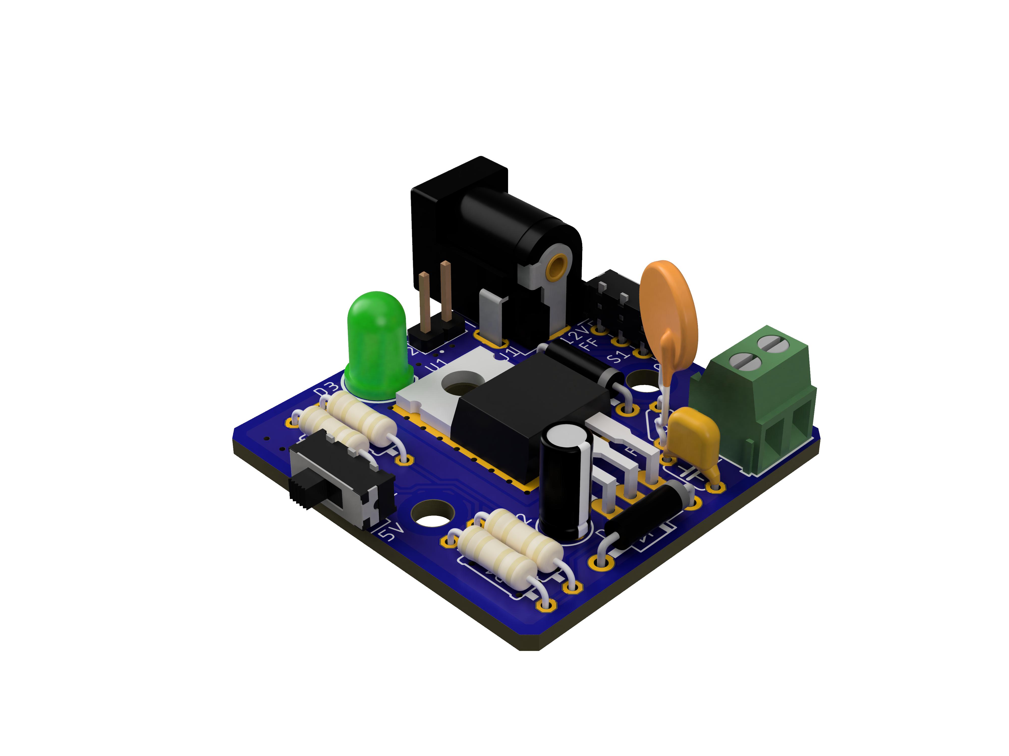
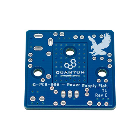
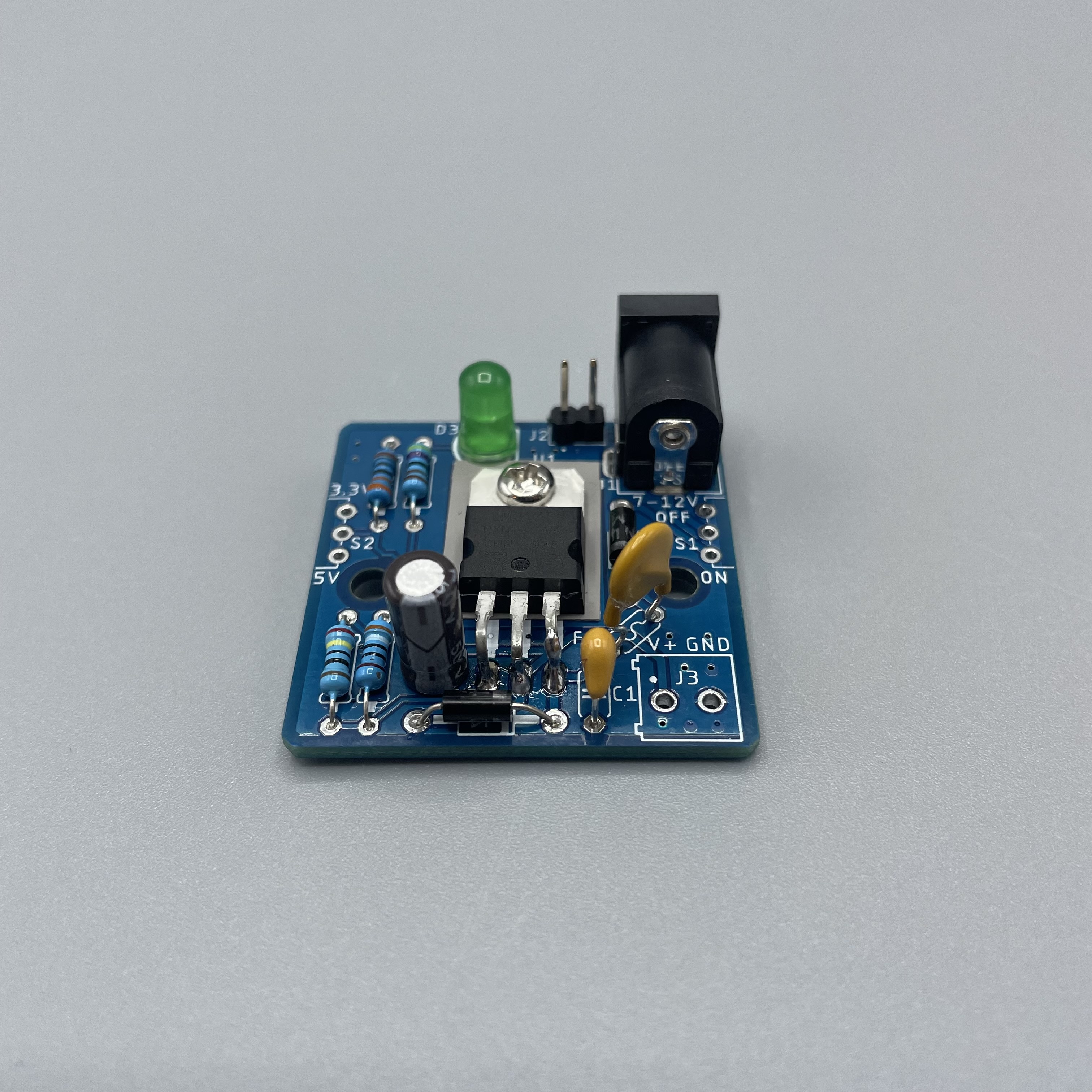
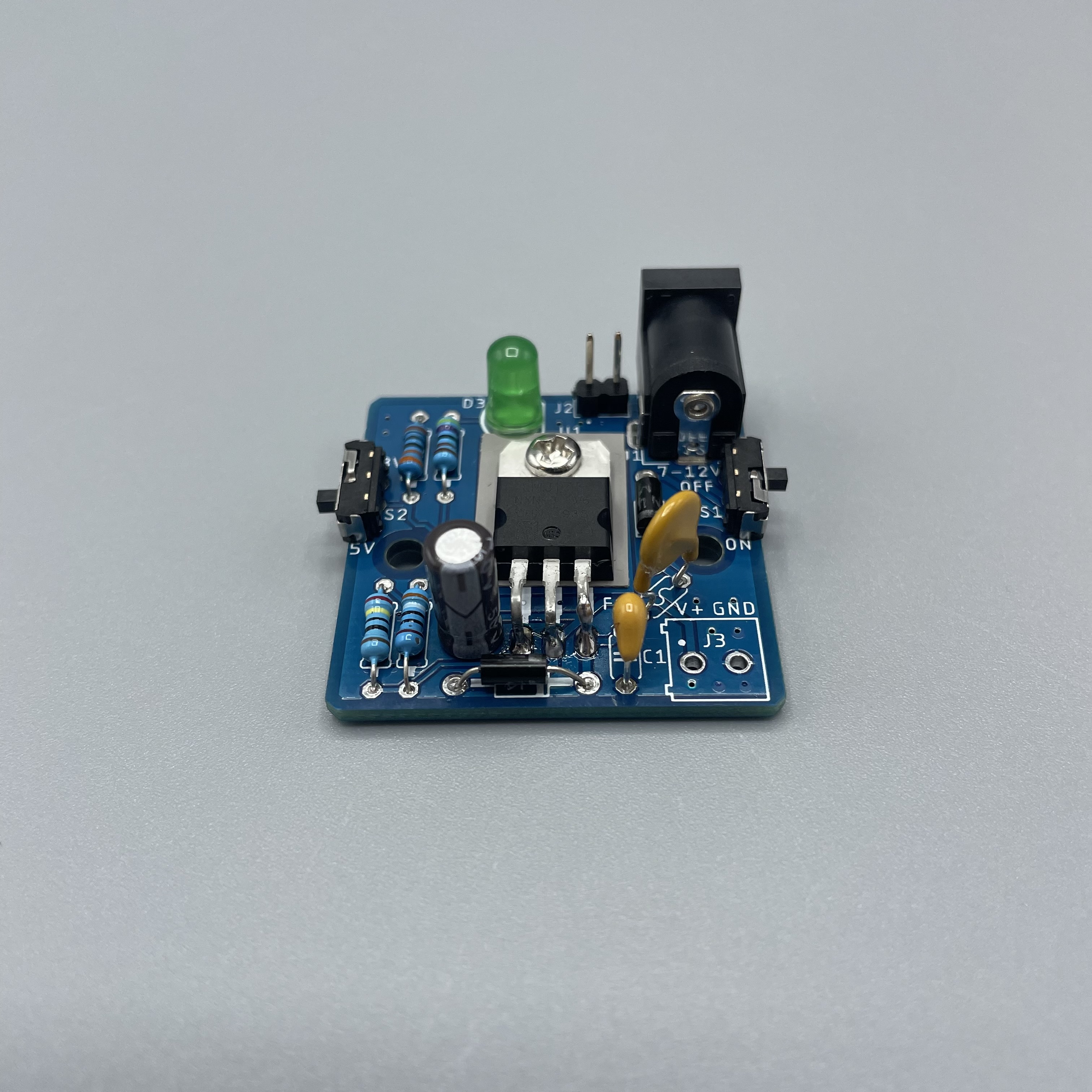
The Flat Power Supply is a redesign of our original Power Supply DIY kit in response to customer requests for a more compact and sleek design. Like its predecessor, this kit converts 7-12V into 3.3 or 5V to power your Builder Base and connected components without being tethered to a wall outlet. You can change the regulated voltage of the kit between 3.3V and 5V with a switch on the PCB to provide the correct voltage that your circuit requires. It also includes multiple terminals that you can use to power circuits at the regulated voltage and/or at the input voltage. Lastly, being able to fold the regulator back and having a finished height less than half of the previous 5V kit provides a smaller profile to fit into even smaller projects.
|
|
Hardware Components
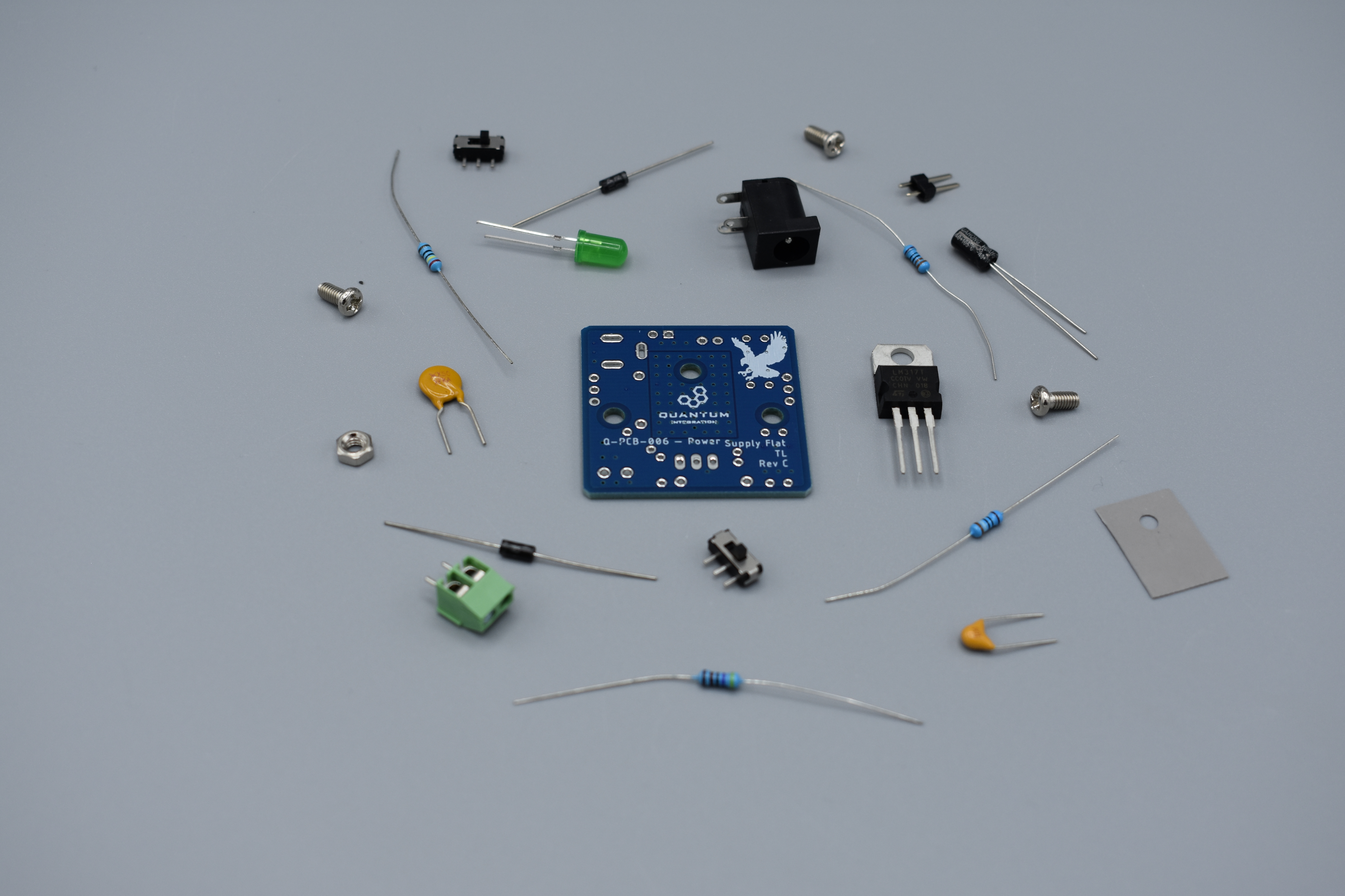
The components are part of the DIY Kit or can be sourced separately with help of the BOM:
| View file | ||
|---|---|---|
|
Picture | Name | Designator | Quantity |
|---|---|---|---|
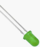 | Radial LED (5mm) | D3 | 1 |
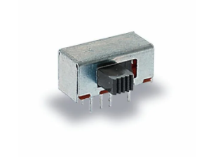 | Sliding Switch | S1, S2 | 2 |
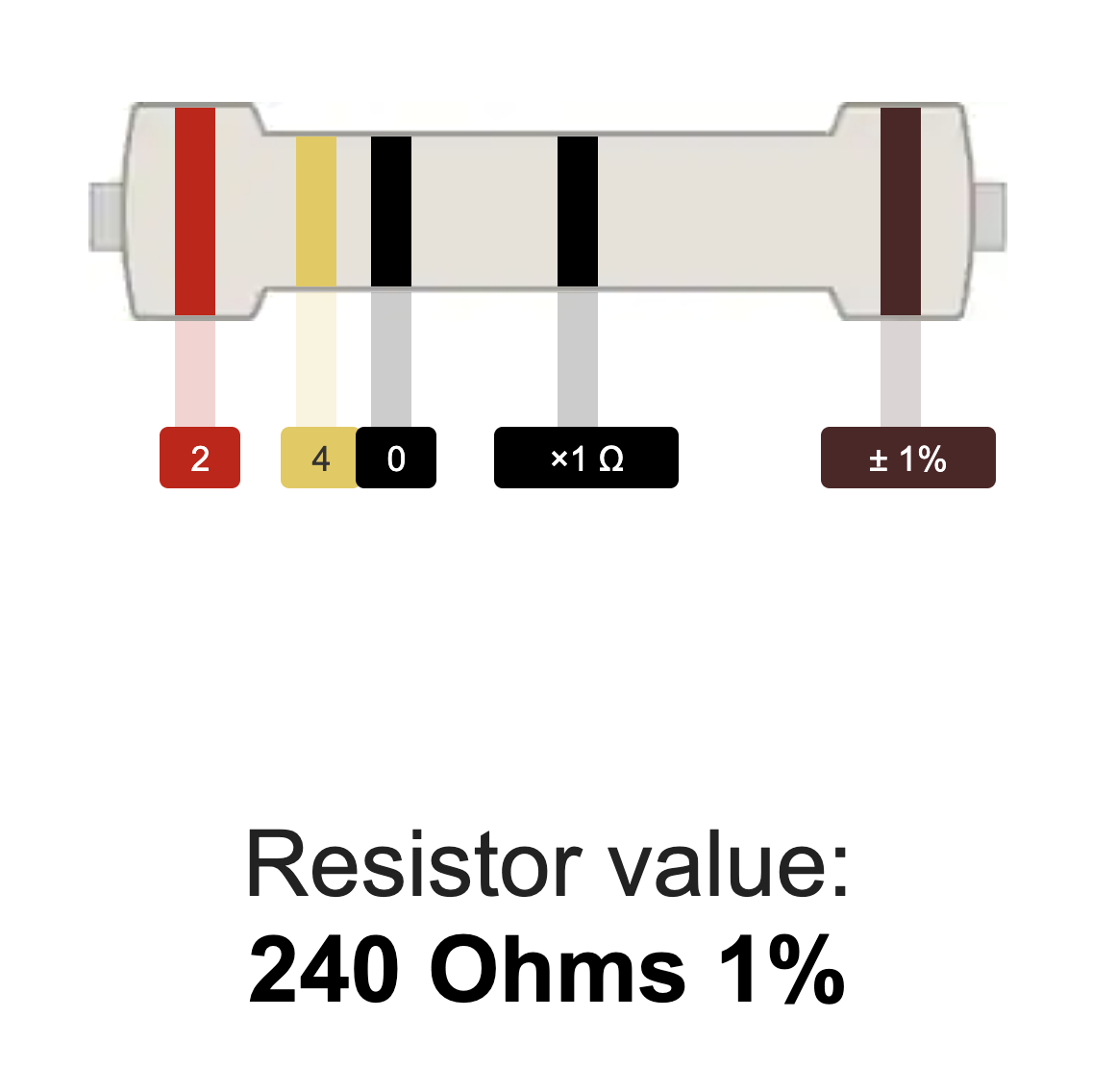
 | 240 Ω Resistor | R1 | 1 |
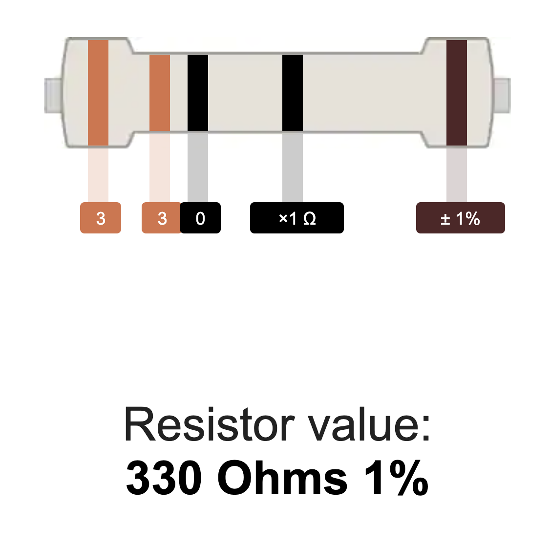 | 330 Ω Resistor | R3 | 1 |
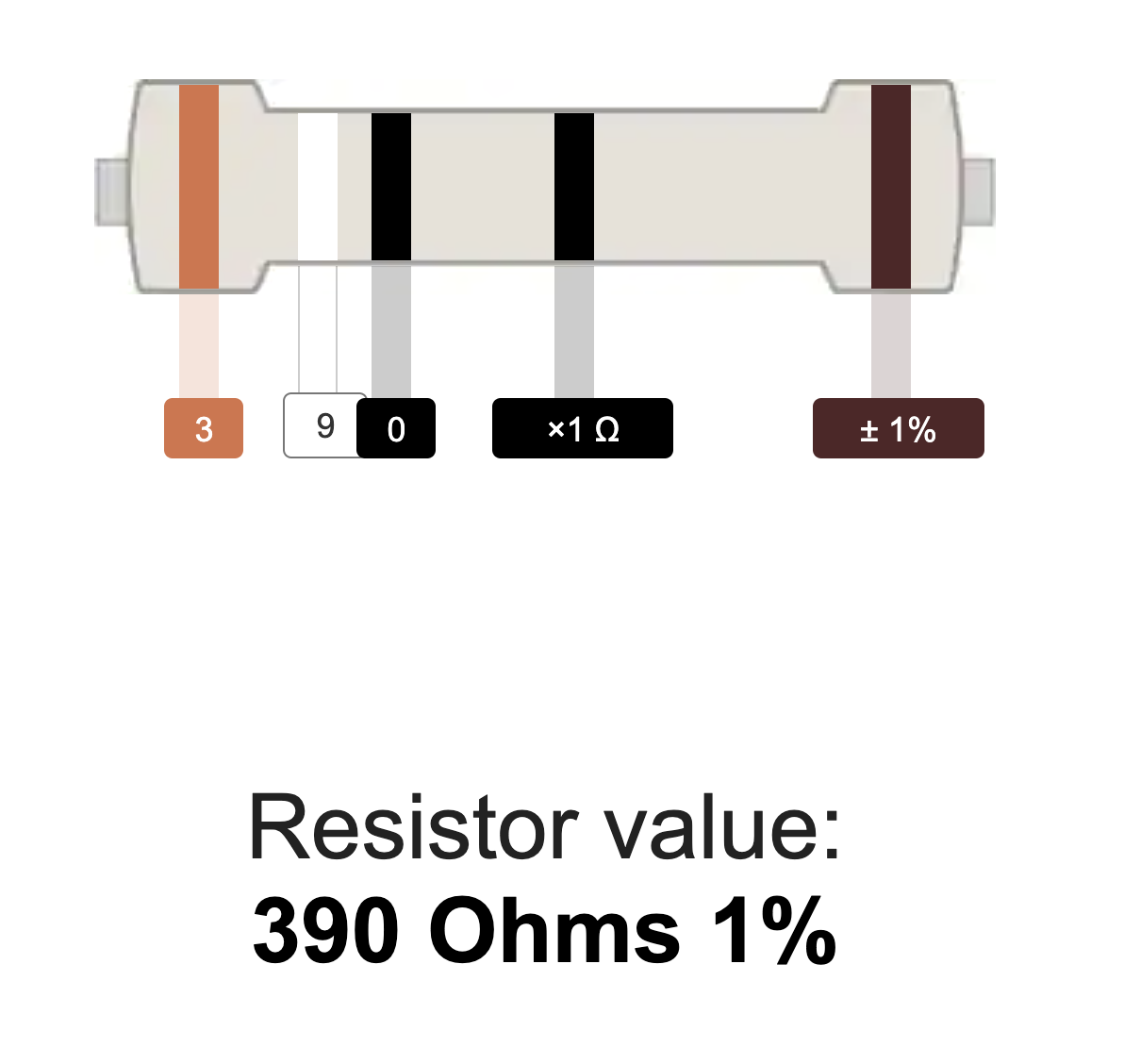 | 390 Ω Resistor | R2 | 1 |
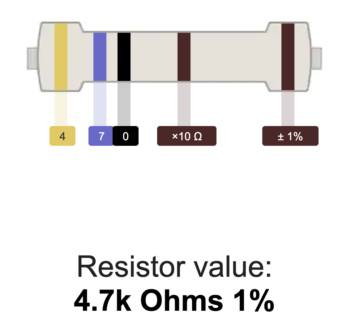
 | 4.7k Ω Resistor | R4 | 1 |
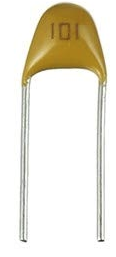 Reads: “104” | 100nf Capacitor | C1 | 1 |
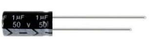 Reads: “1µF” | 1uf Polarized Capacitor | C2 | 1 |
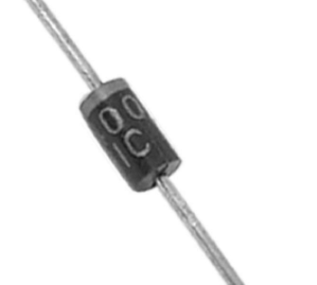 | 1N4000 Diode | D1, D2 | 2 |
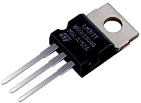 | LM317MB | U1 | 1 |
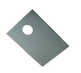 | Heatsink Pad | 1 | |
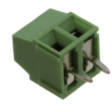 | 1x2 3.5mm Terminal Block | J3 | 1 |
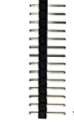 | 1x2 pin header | J2 | 3 |
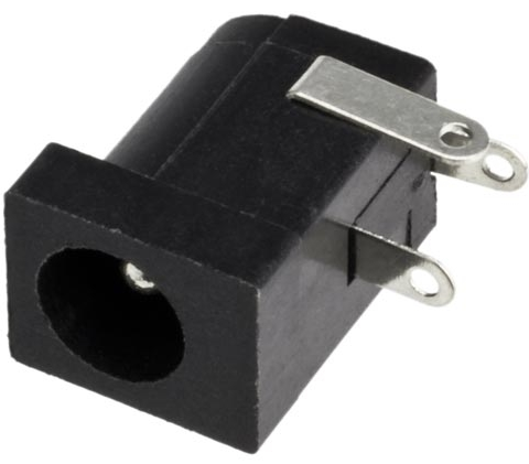 | 2.1mm Barrel Jack | J1 | 1 |
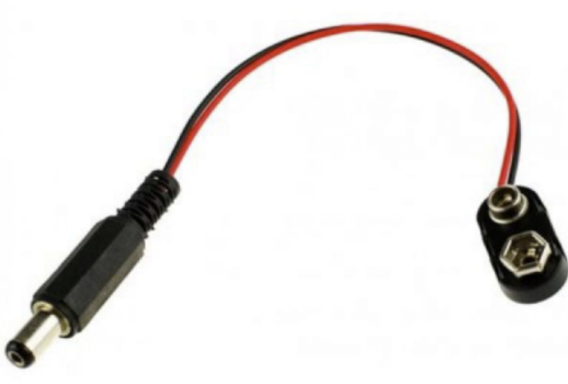 | 2.1mm Barrel Jack to 9V adapter | 1 | |
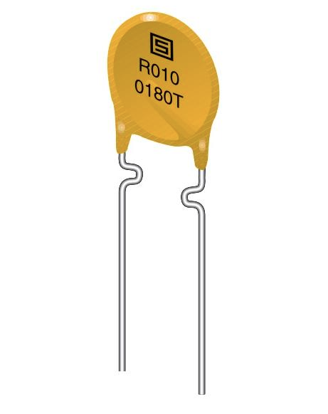 | PTC Fuse | F1 | 1 |
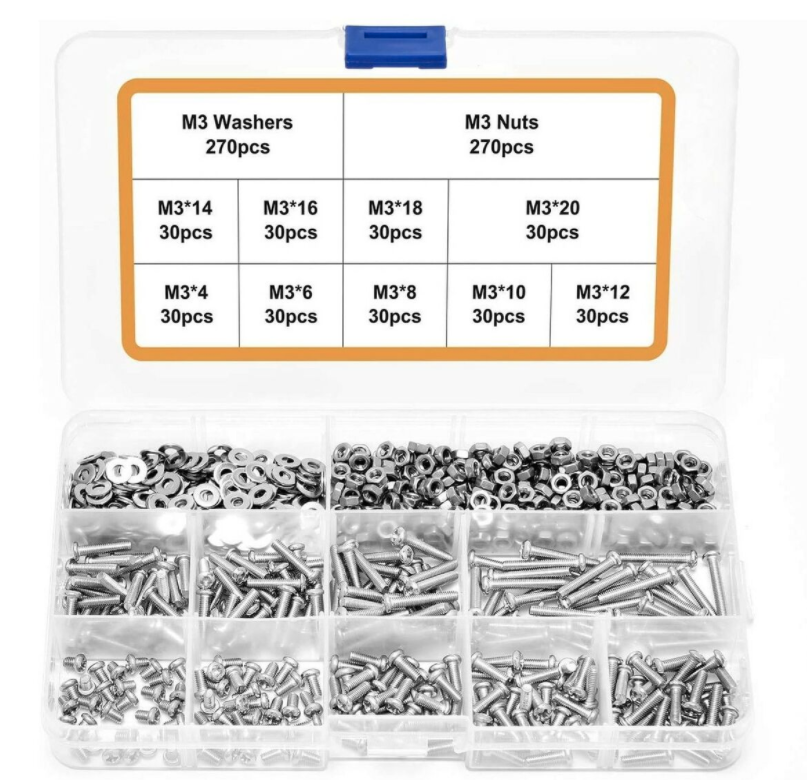 | Mounting Hardware
| 4 | |
 | Power Supply PCB | Q-PCB-006 | 1 |
Tools Used
Picture | Name | Quantity | Link |
|---|---|---|---|
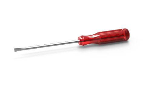 | Small slotted-head screwdriver | 1 | Included in Component Kit Or you can pick from one on our Recommended Tools List |
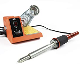 | Soldering Iron | 1 | You can pick from one on our Recommended Tools List |
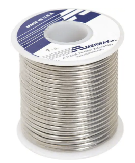 | Solder | 1 | You can pick from one on our Recommended Tools List |
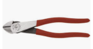 | Diagonal Cutters | 1 | You can pick from one on our Recommended Tools List |
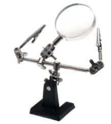 | Work Holder | You can pick from one on our Recommended Tools List |
PCB Assembly and Soldering
Place groups of components on the board and then solder them to the pads.
Using some form of work holder is advised. You can find a list of suitable work holders on our Recommended Tools List.

We will start by putting all the parts on the table.
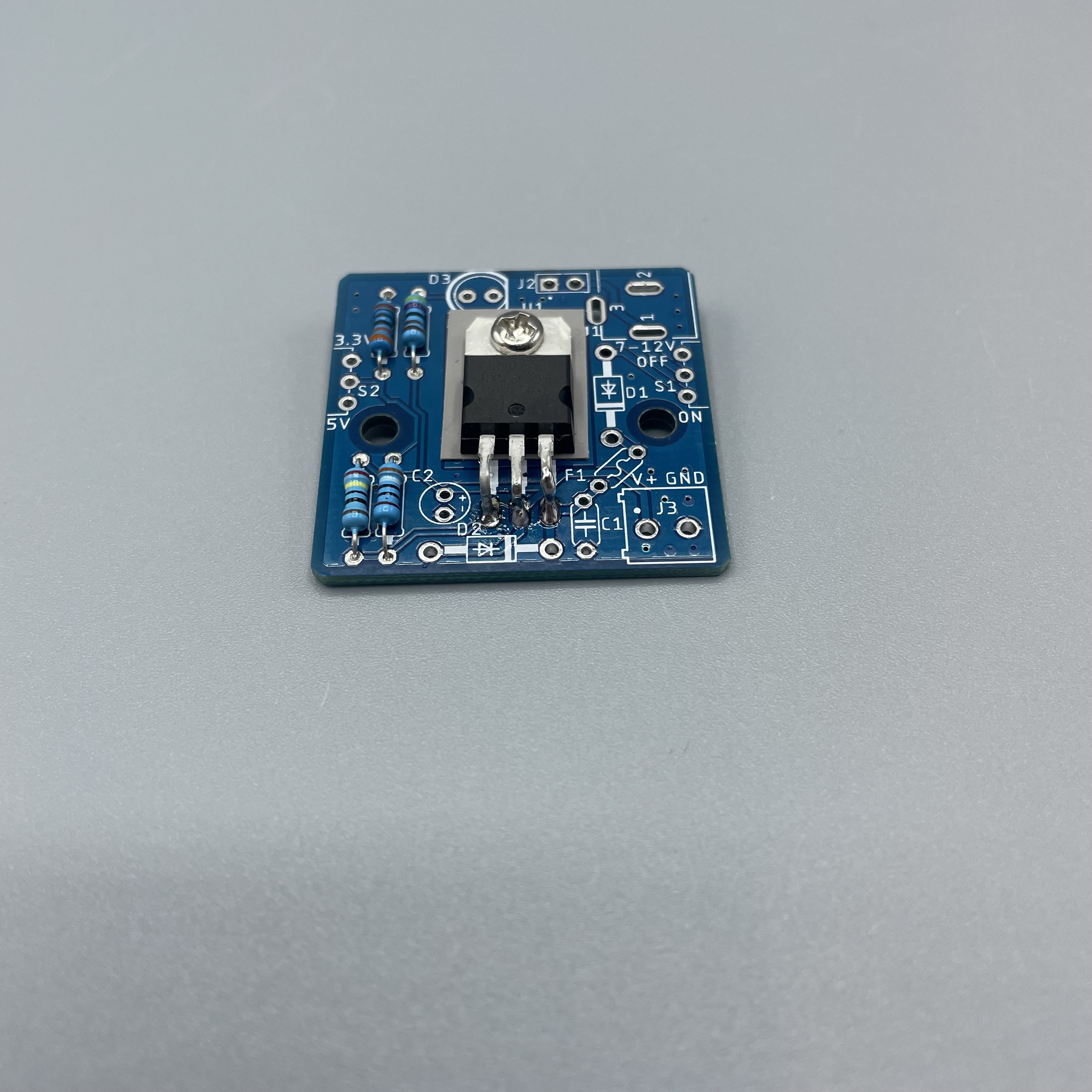
Start by soldering the heat sink. Bent it over and solder the three connections to the board.
Next are the resistors. Use the table and pictures to identify them.
R1: 240Ω Resistor
R2: 390Ω Resistor
R3: 330Ω Resistor
R4: 4.7kΩ Resistor
 |  |  |  |
Solder the diodes on D1 and D2.
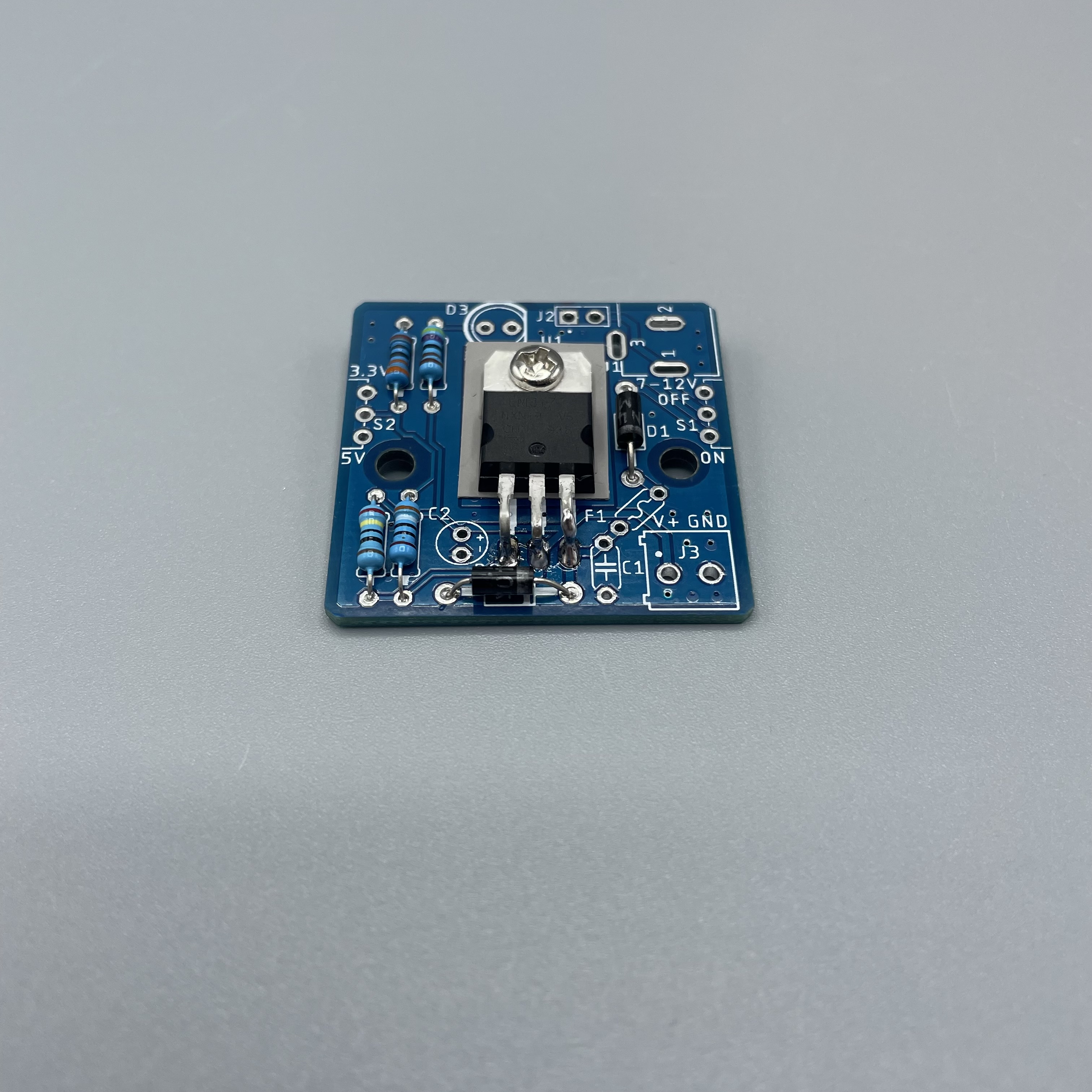
Solder the Fuse on F1.
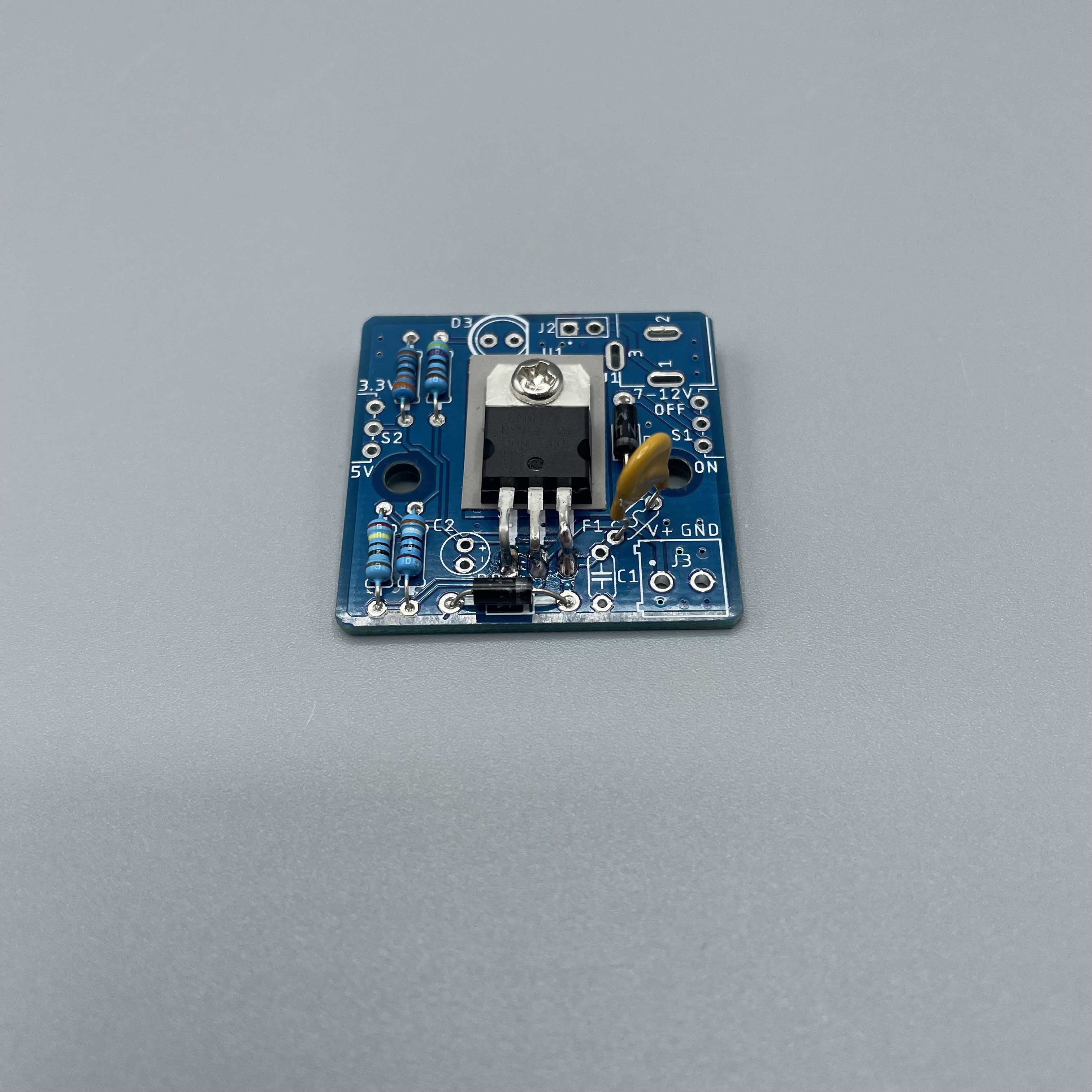
Now we solder the capacitors. The black one with 1µF goes onto C2. Remember that the long pin is the positive side. The PCB will show you which one is the positive side. The yellow one which reads “104“ is not polarized so it has no positive or negative side. Solder it onto C1.
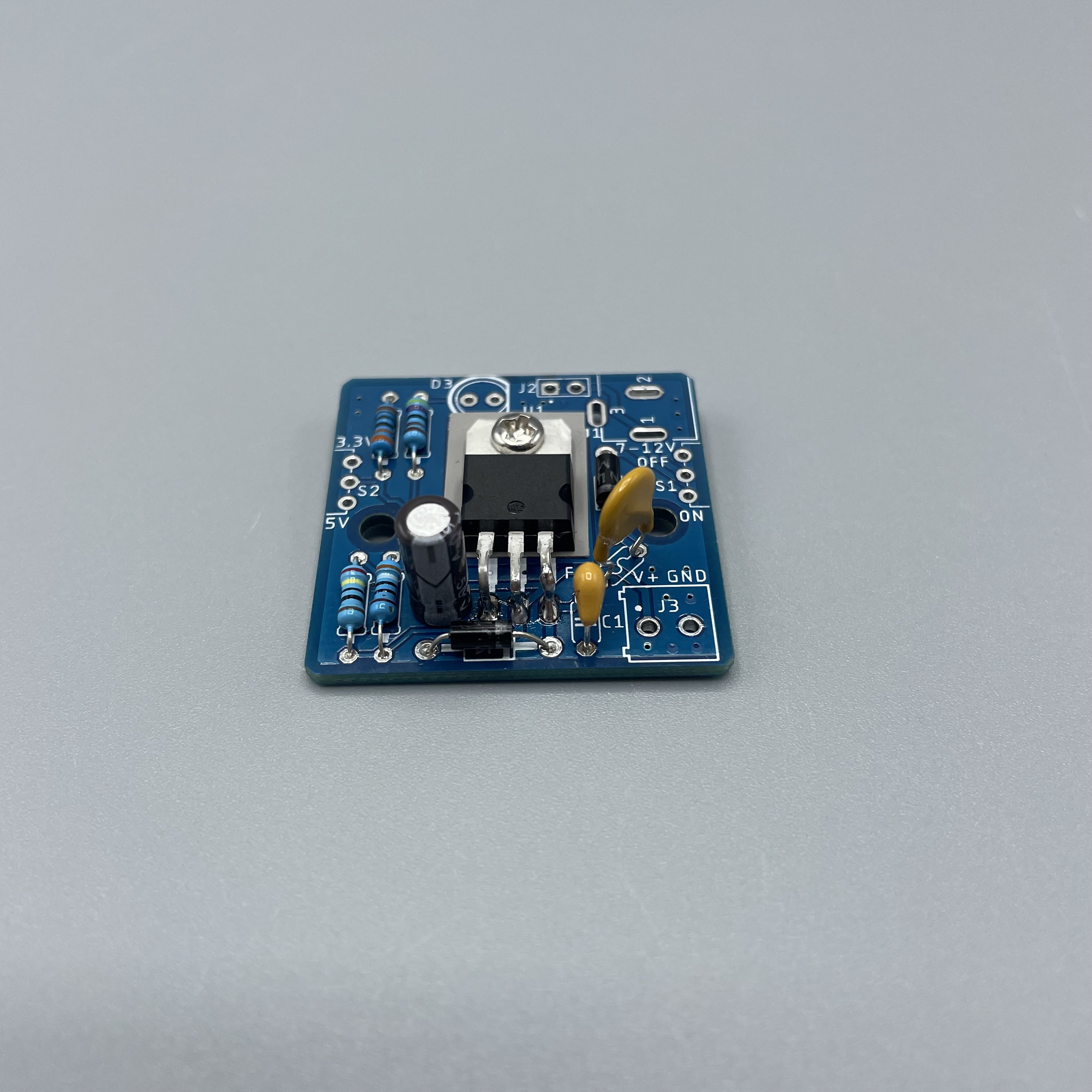
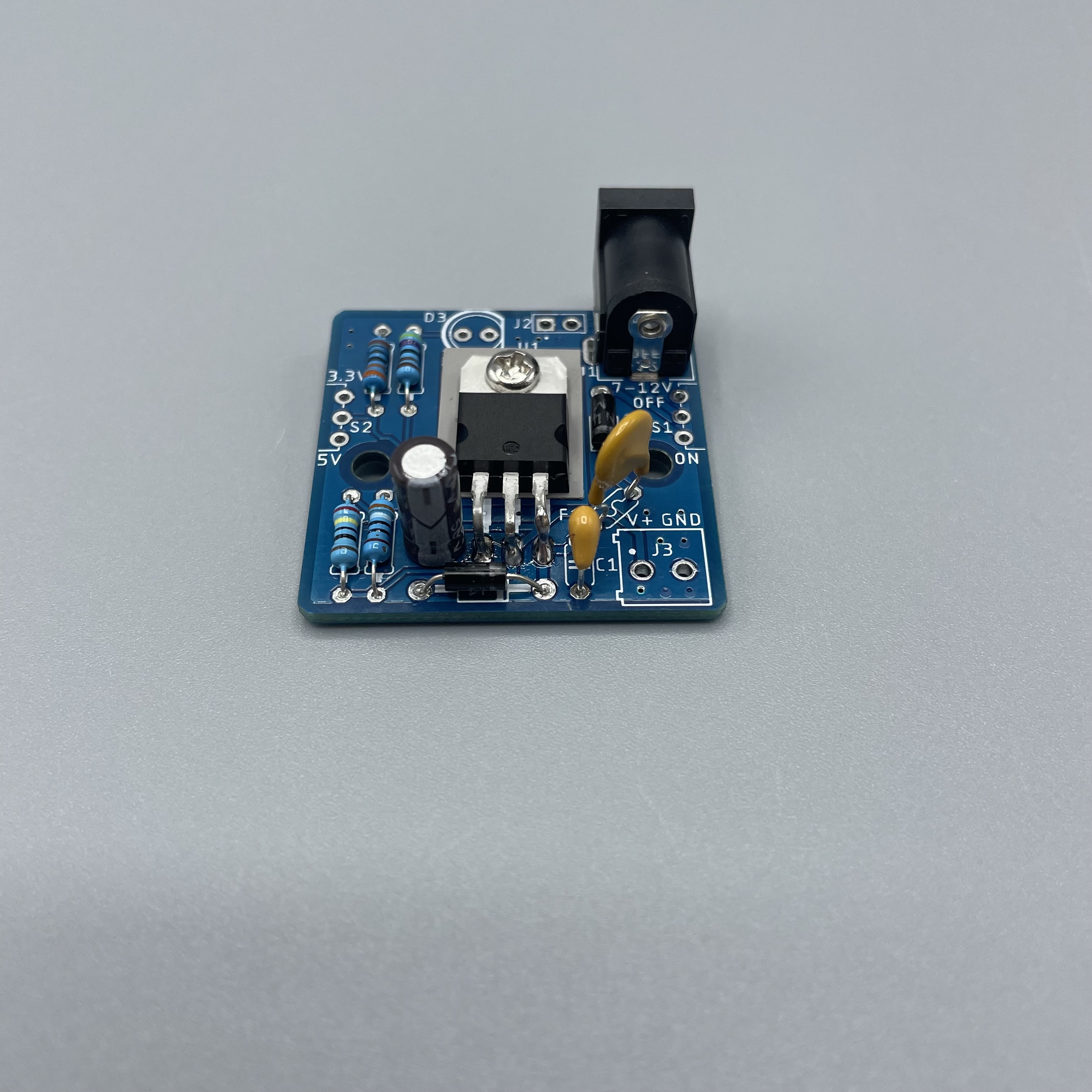
Solder the barrel jack. Make sure it faces away from the board.
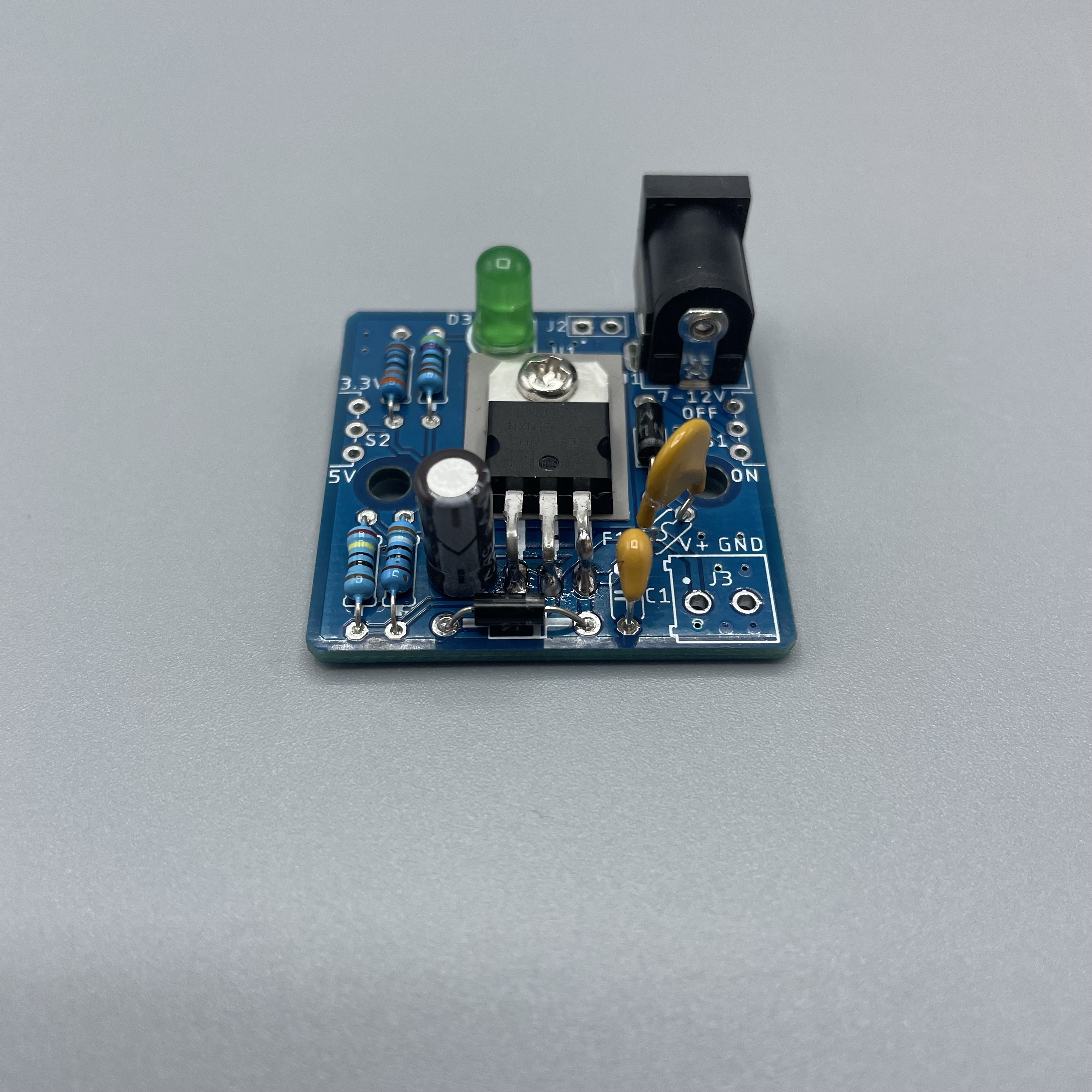
Solder the LED on D3. Remember there is a flattened side of the LED which is also projected on the PCB. The longer pin is the positive side.
Solder the pin header on J2.
Solder both switches. Make sure they face away from the board.
Lastly solder the terminal on J3.
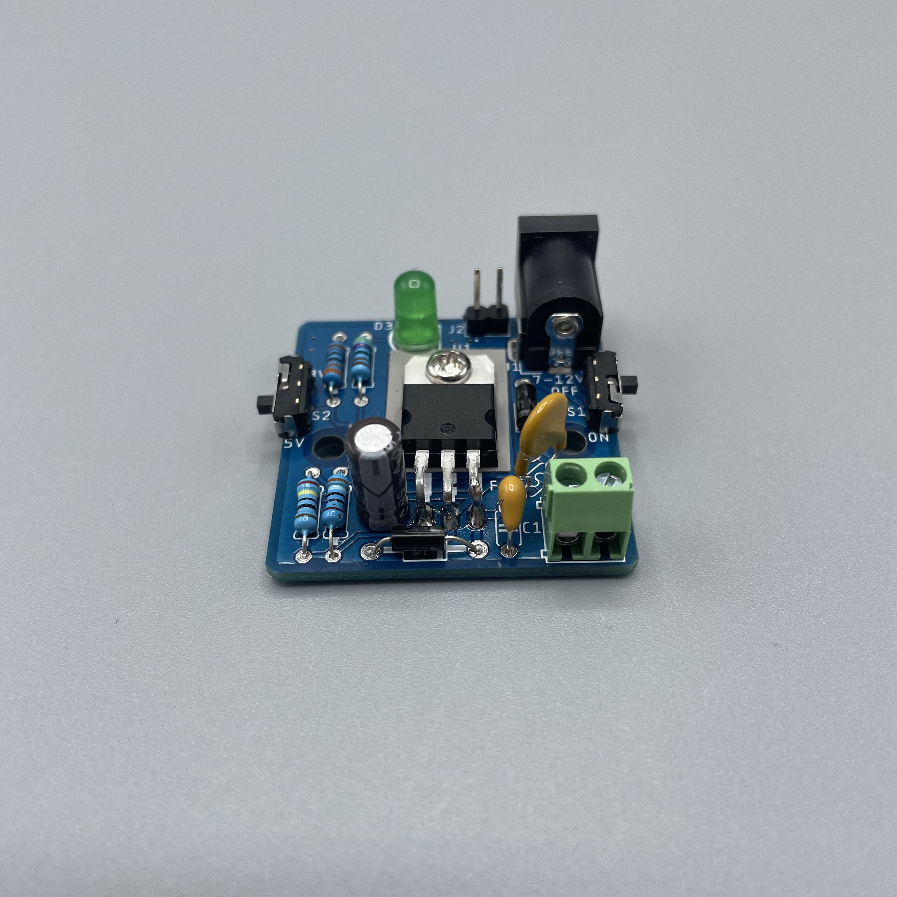
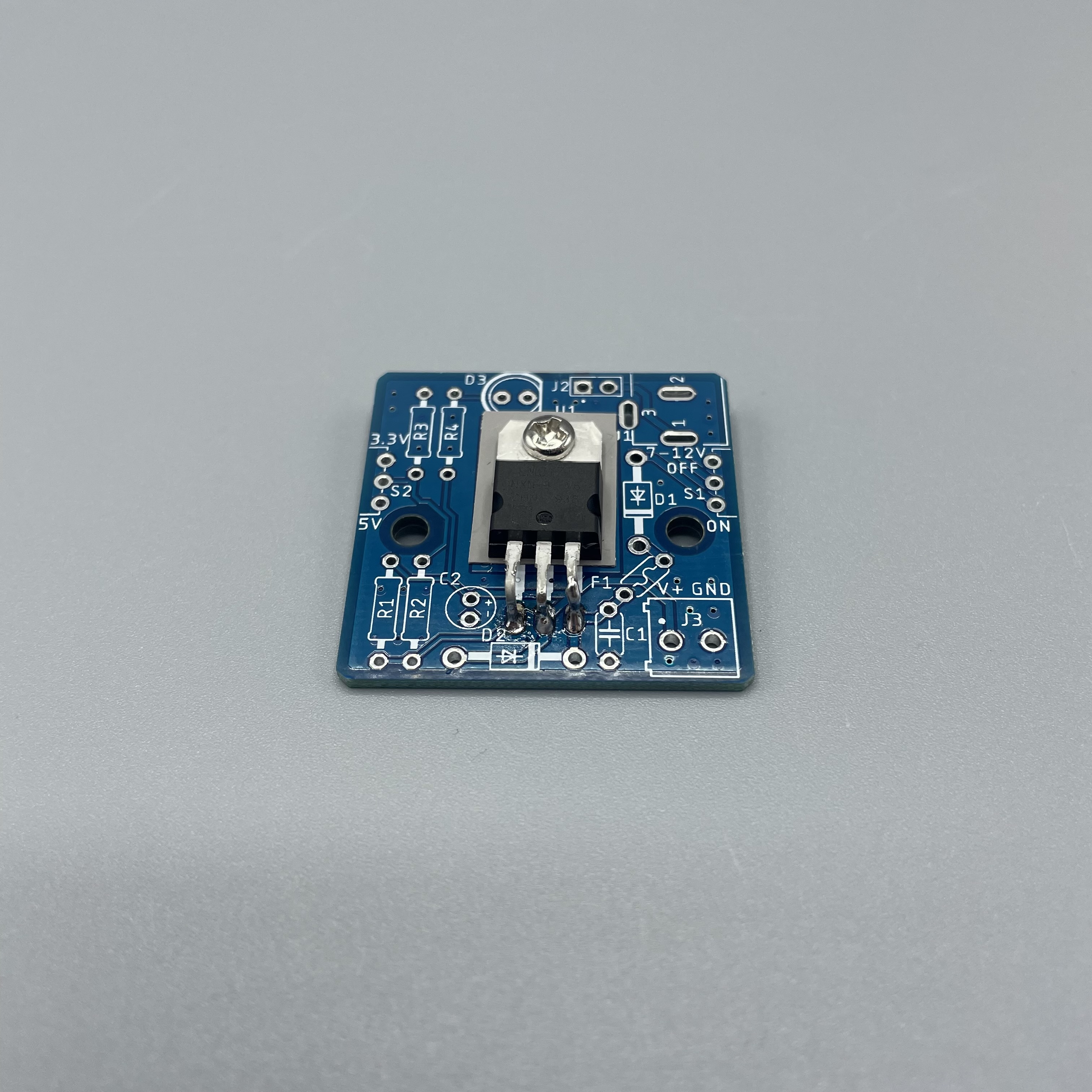
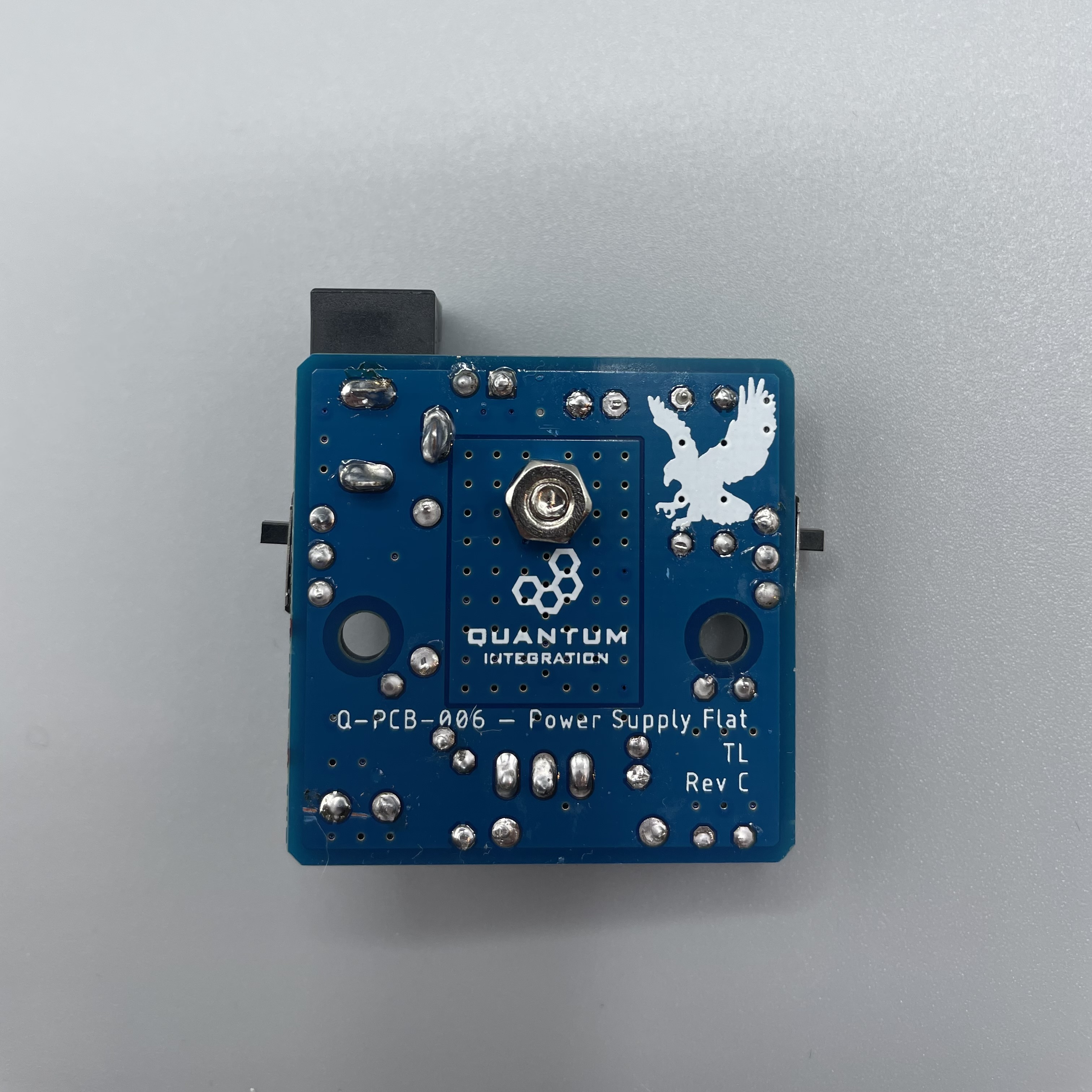
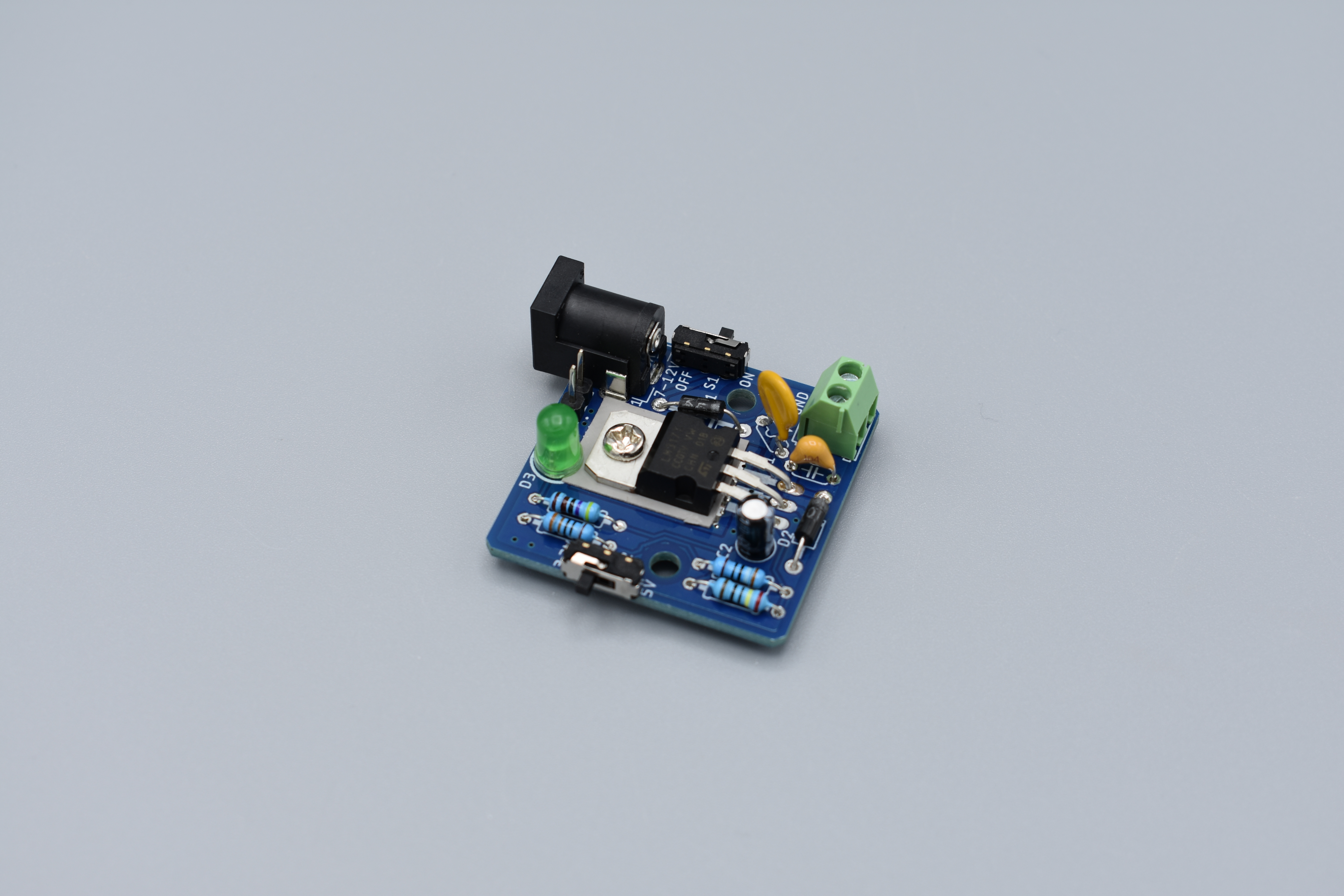
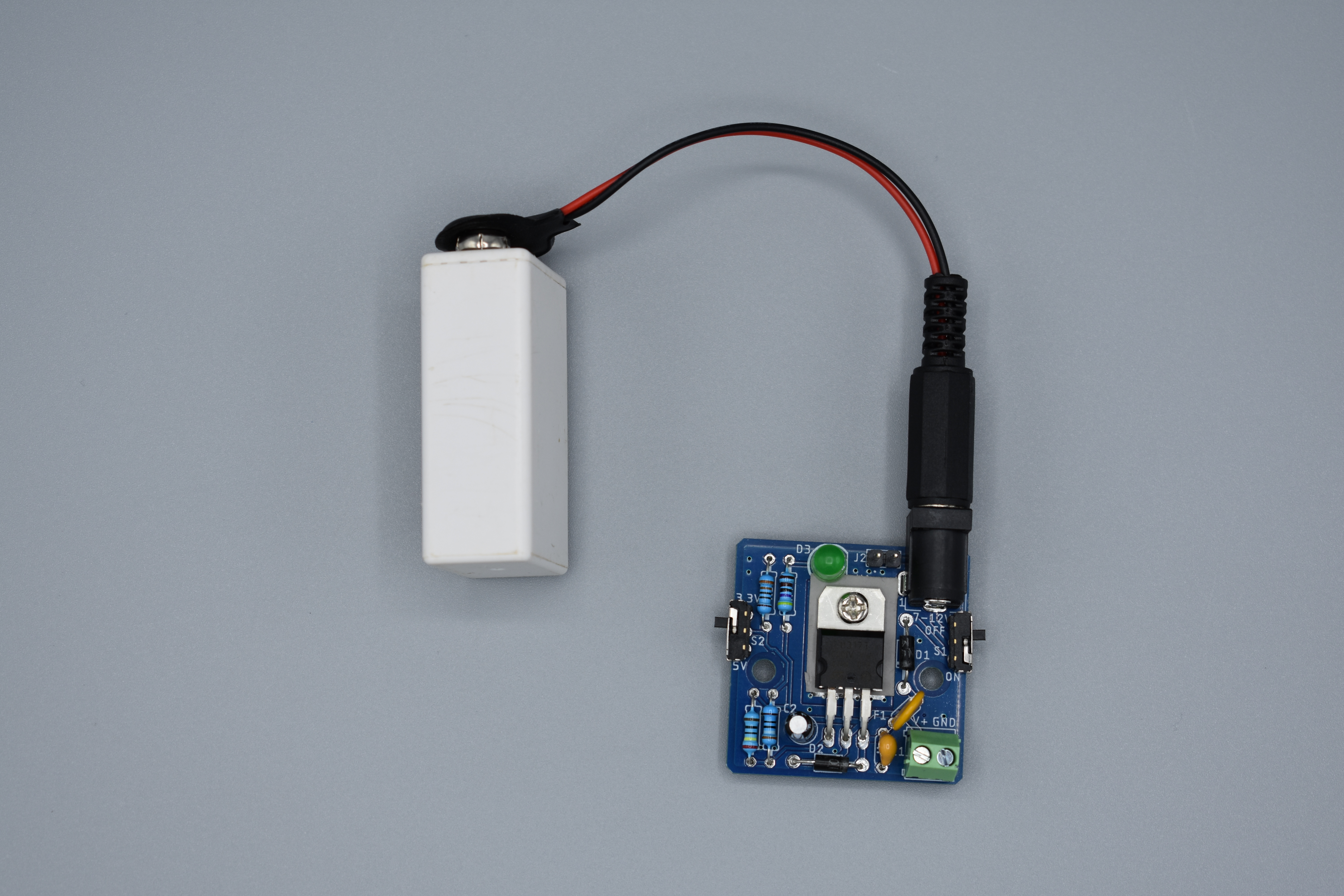
Your Flat Power Supply DIY Kit is ready to be used! The back should look like this.
Connecting to the Builder Base
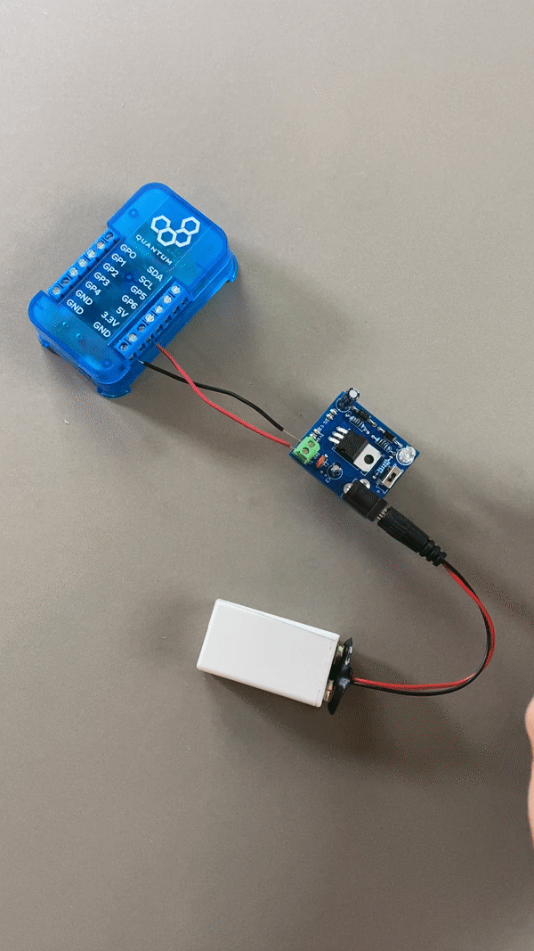
Please refer to the following image on how to connect the DIY Kit to the Builder Base.
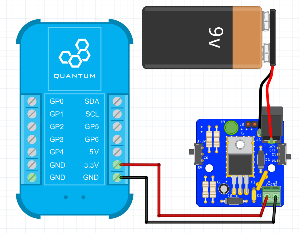
You have two options for connecting the power supply to your Builder Base: you can use the male headers on the bottom of your PCB to stick it on the GND and VCC rails of a bread board, or you can use the screw terminals located on the top of your power supply. Both options serve the same purpose, but one might work better for a given project than the other. If you are using the image above as a reference make sure to have the switch in the 3.3V position. If you want to change to 5V also change the wires to the 5V Terminal at the Builder Base. You know that your DIY Kit is powered and ready to be used when the LED lights up.
Projects
The Power Supply DIY Kit can be used in a variety of projects! It can power your Builder Base or your entire Breadboard circuit!
Gallery
Resources
This DIY Kit page is currently optimized for revision C.
Current revision
Assembly files for the current revision of the DIY Kit (Rev C): | https://github.com/QuantumIntegration/Q-PCB-006-Power-Supply-Flat-Hardware-Files |
|---|
Older revisions
- | - |
|---|