| Table of Contents |
|---|
Overview
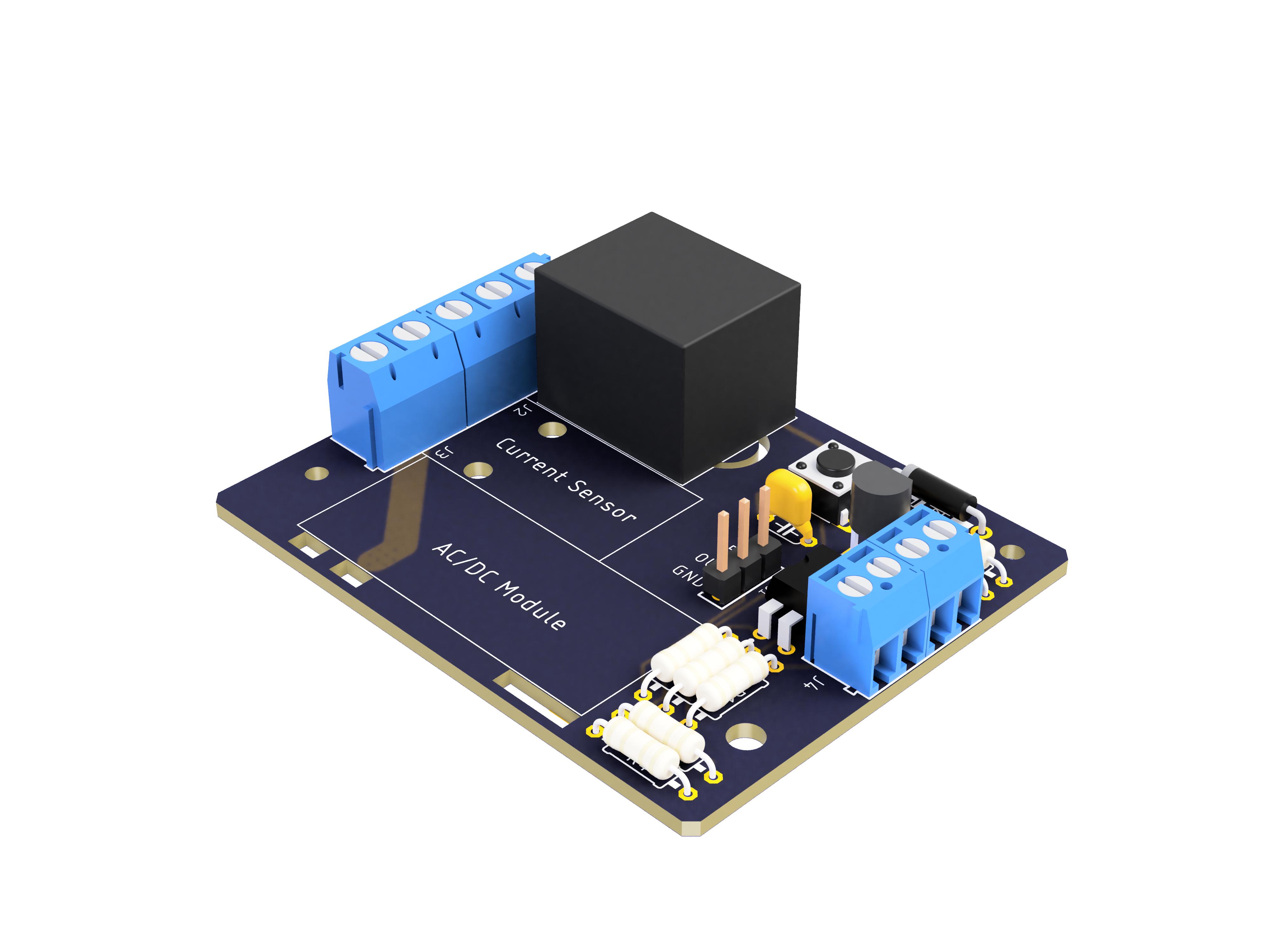
The Outlet Switch DIY Kit can control the power of an outlet with the Quantum platform. An outgrowth of Quantum’s Smart Outlet project, this kit is wired to a Builder Base and outlet and can fit into a standard outlet box. It takes in up to 240V AC or 30V DC at 10 amps, and uses a relay switch to power the outlet on/off. This allows you to control the power of an outlet from the Quantum dashboard on any smart device or with a trigger component like a pushbutton on the IR remote.
|
|
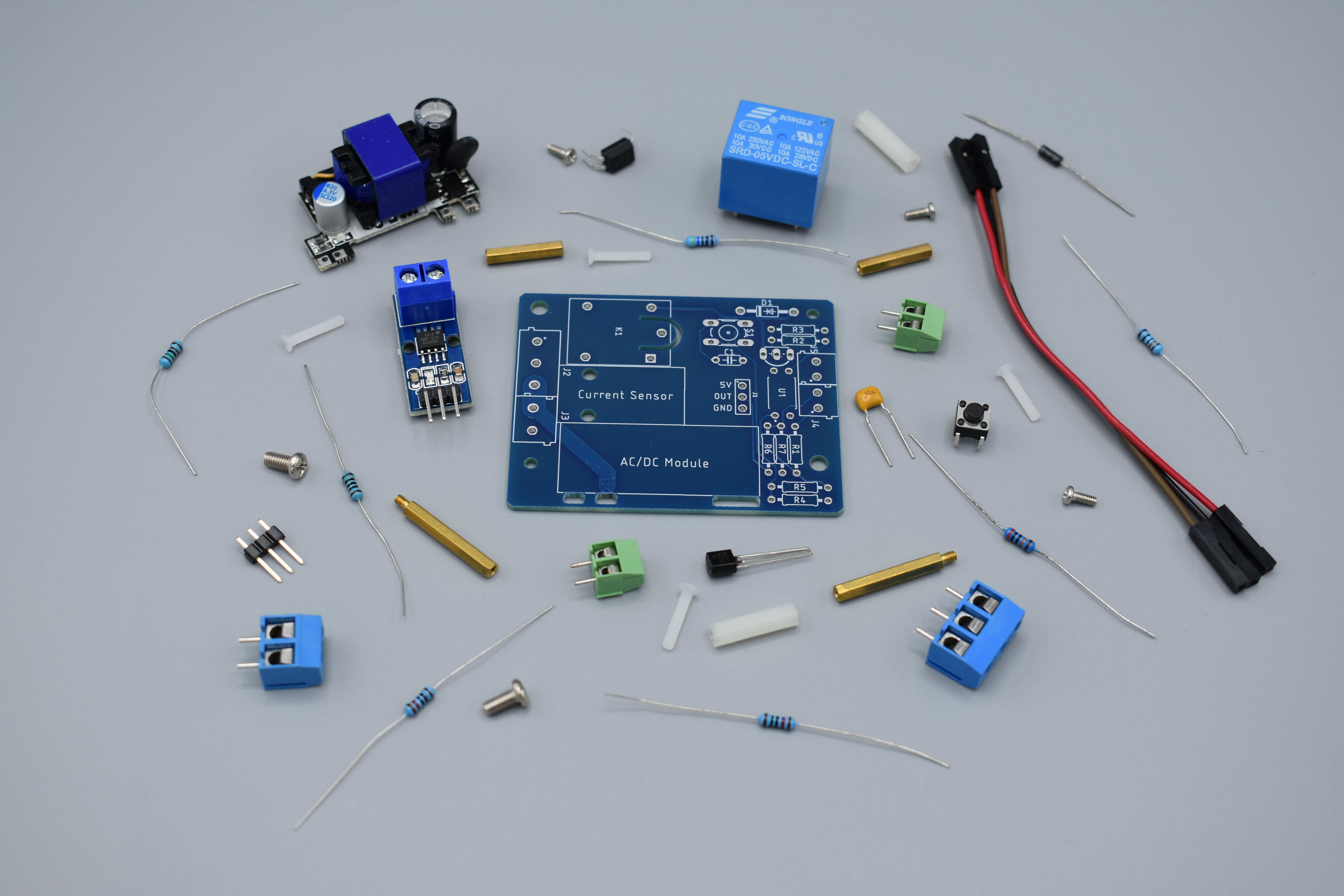
Hardware Components
The components are part of the DIY Kit or can be sourced separately with help of the BOM:
| View file | ||
|---|---|---|
|
Picture | Name | Designator | Quantity |
|---|---|---|---|
Reads: “104” | 100nf Capacitor | C1 | 1 |
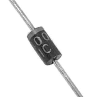 | 1N4000 Diode | D1 | 1 |
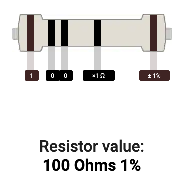 | 100 Ω Resistor | R1 | 1 |
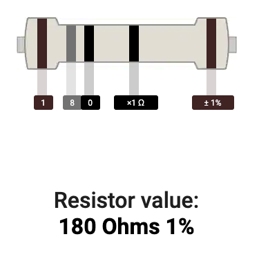 | 180 Ω Resistor | R5 | 1 |
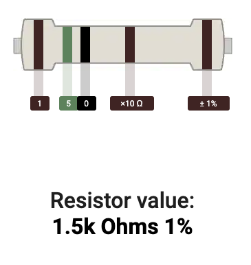 | 1.5 kΩ Resistor | R2 | 1 |
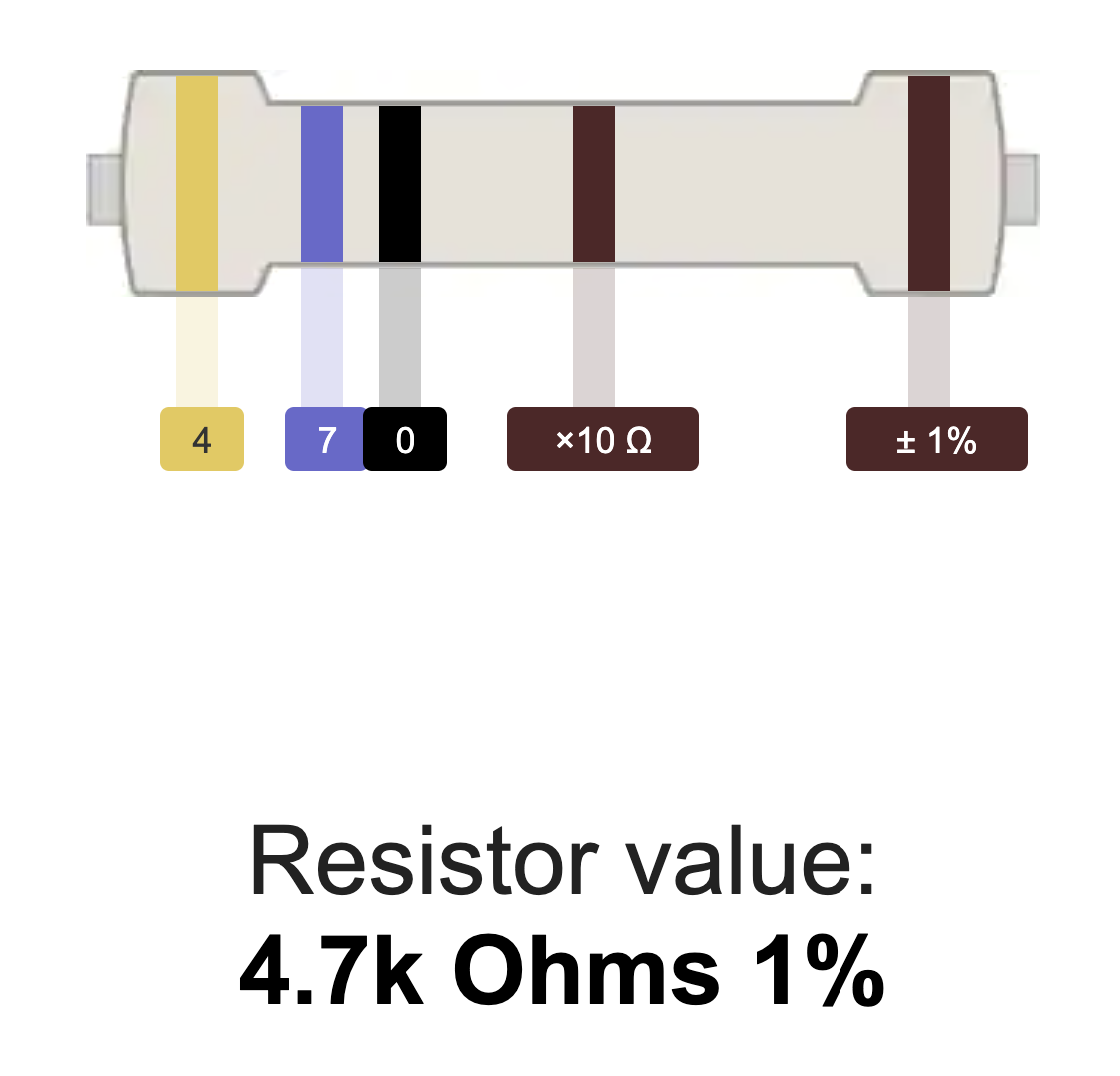 | 4.7 kΩ Resistor | R3 | 1 |
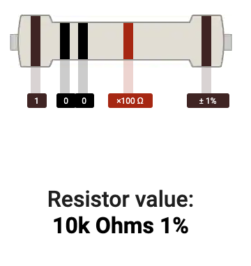 | 10 kΩ Resistor | R4 | 1 |
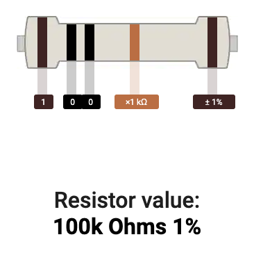 | 100 kΩ Resistor | R6 | 1 |
 | 200 kΩ Resistor | R7 | 1 |
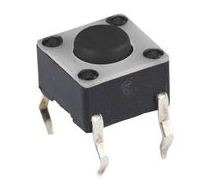 | Tactile Push Button | S1 | 1 |
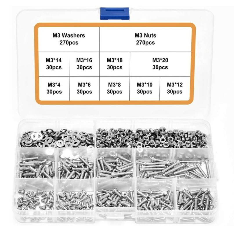 | Mounting Hardware
| 18 | |
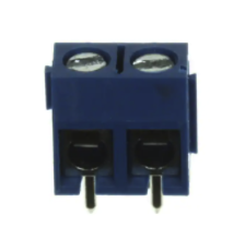 | Terminal | J2, J3 | 2 1/2 |
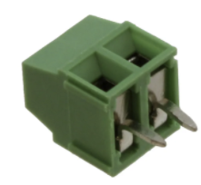 | 1x2 3.5mm Terminal Block | J4, J5 | 2 |
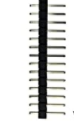 | 1x3 male pin header | J1 | 1 |
Transistor NPN | Q1 | 1 | |
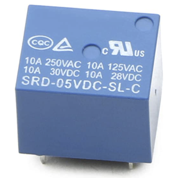 | Relay | K1 | 1 |
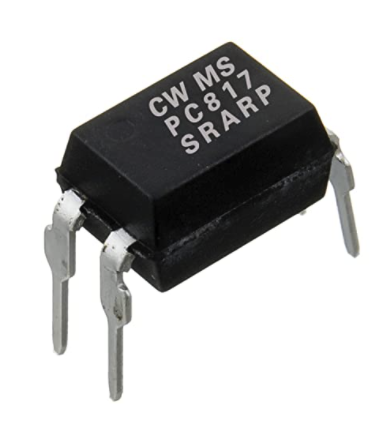 | Octocoupler | U1 | 1 |
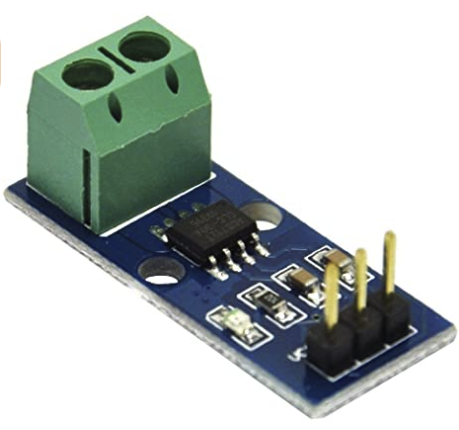 | Current Sensor | 1 | |
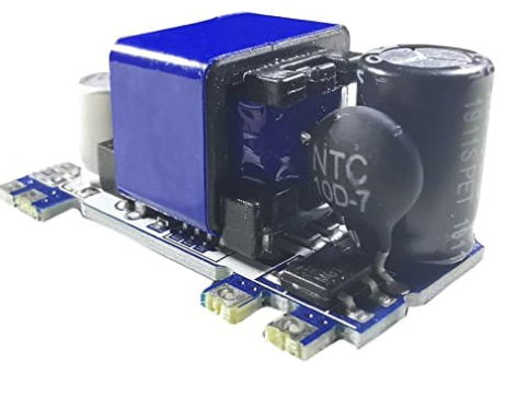 | Power Supply | 1 | |
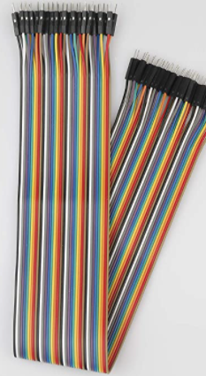 | Jumper Wires FF | 3 | |
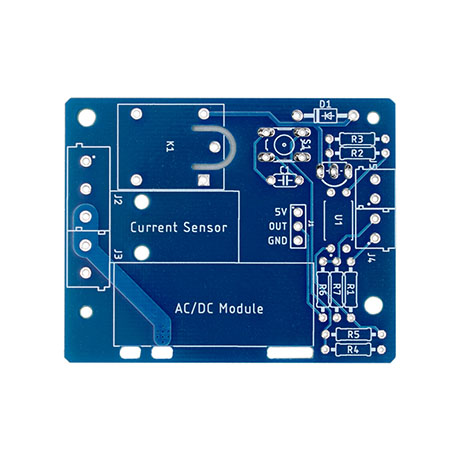 | Switched Outlet PCB | Q-PCB-007 | 1 |
Tools Used
Picture | Name | Quantity | Link |
|---|---|---|---|
Small flat-head screwdriver | 1 | Included in Component Kit or you can pick from one on our Recommended Tools List | |
Soldering Iron | 1 | You can pick from one on our Recommended Tools List | |
Solder | 1 | You can pick from one on our Recommended Tools List | |
Diagonal Cutters | 1 | You can pick from one on our Recommended Tools List | |
Work Holder | 1 | You can pick from one on our Recommended Tools List |
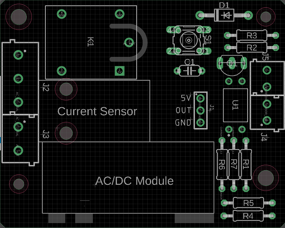
PCB Assembly and Soldering
Place groups of components on the board and then solder them to the pads.
Using some form of work holder is advised. You can find a list of suitable work holders on our Recommended Tools List.

We will start by putting all the parts on the table.
If you are not familiar with soldering you should start with components with the lowest profile, like for example resistors and then move up to components like buttons with higher profile.
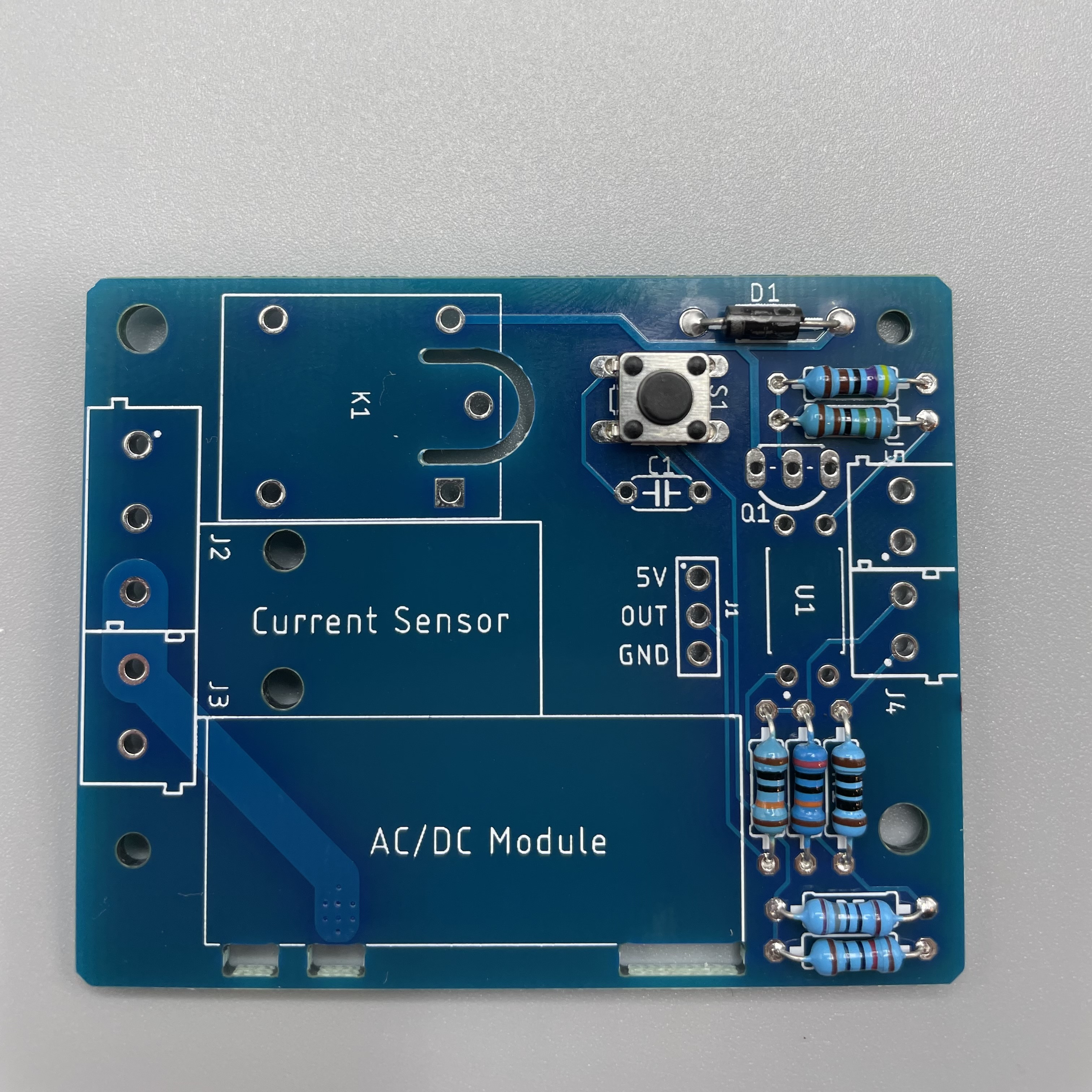
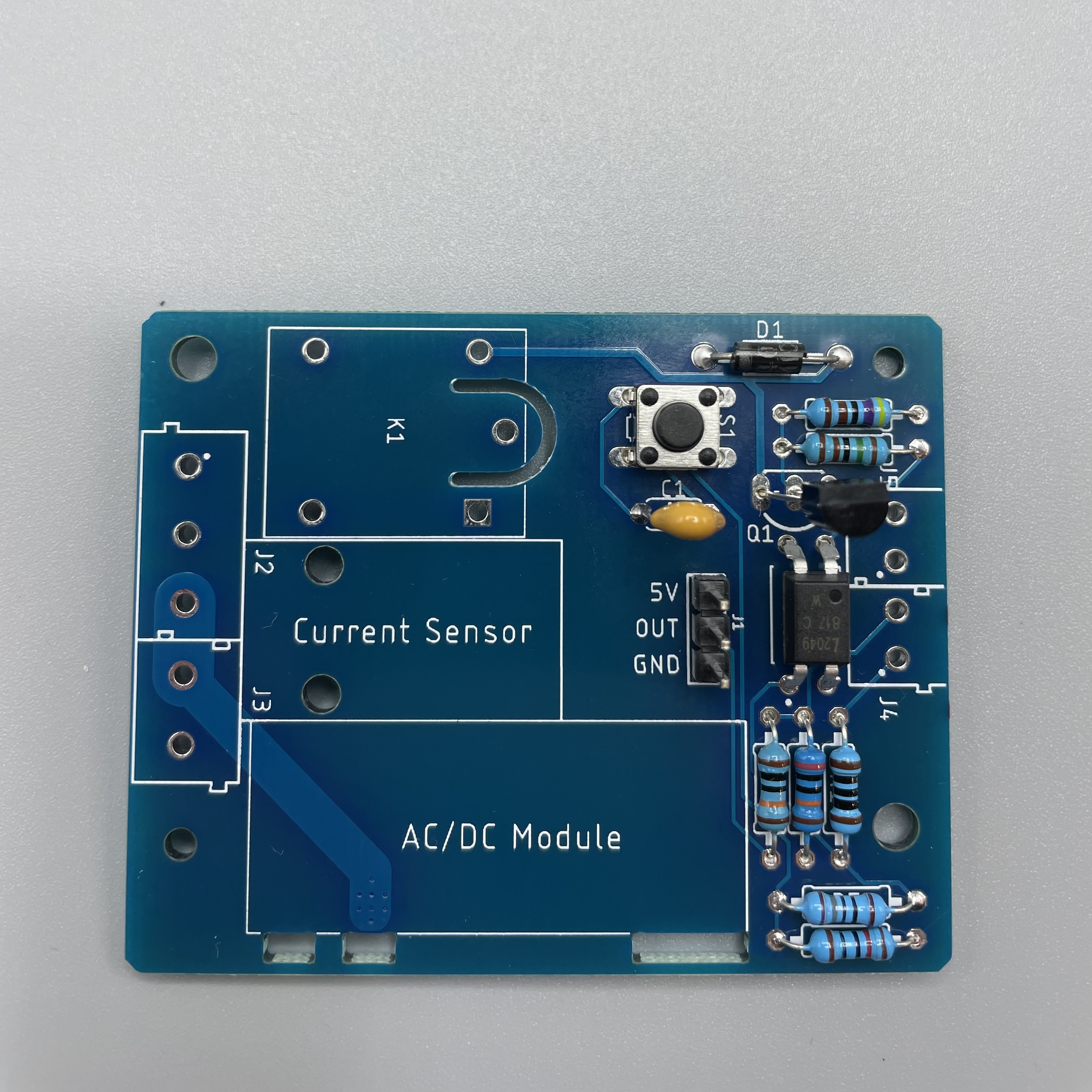
Solder the Diode on D1. Make sure it has the right direction.
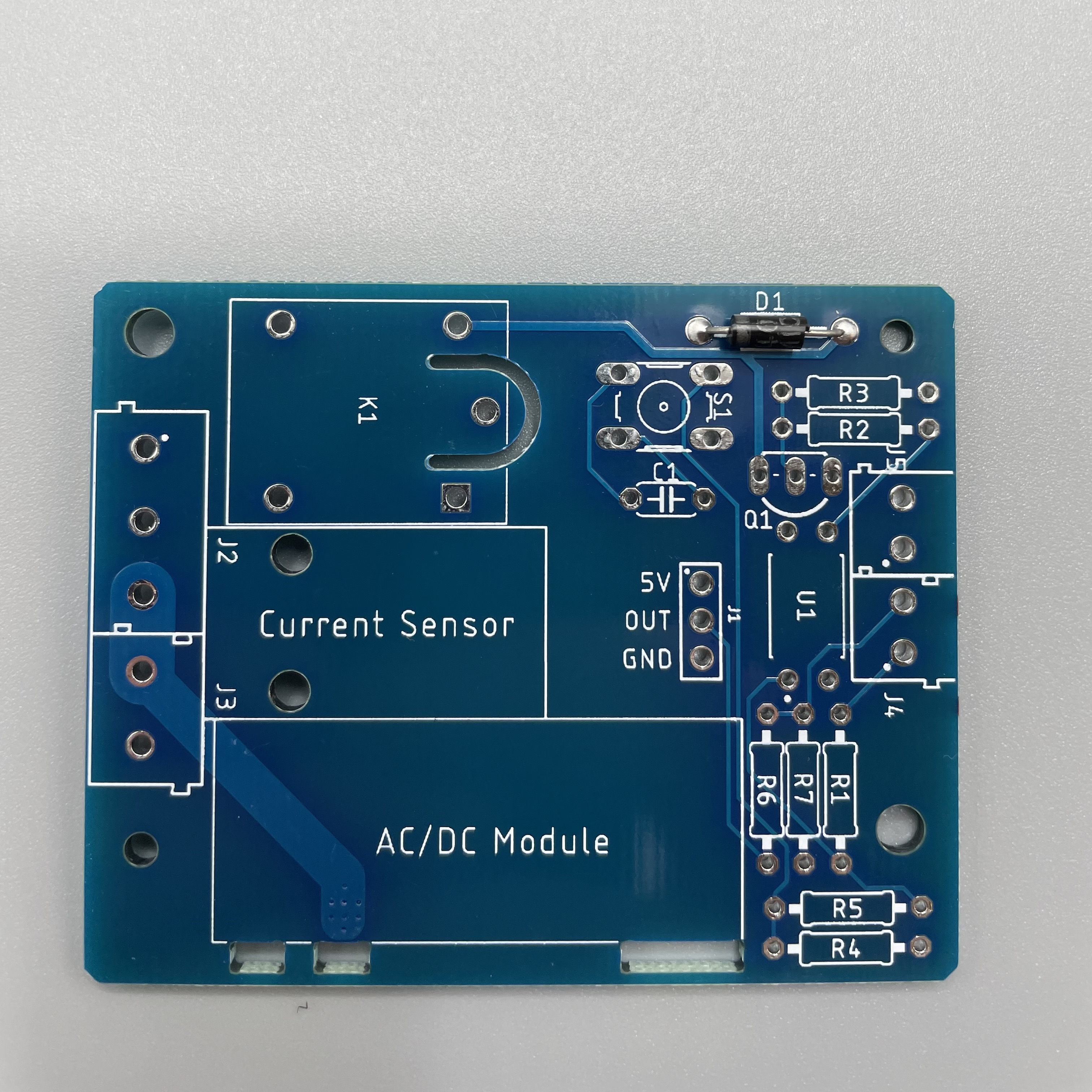
Next are the resistors. Use the table and pictures to identify them.
R1: 100 Ω Resistor
R2: 1.5 kΩ Resistor
R3: 4.7 kΩ Resistor
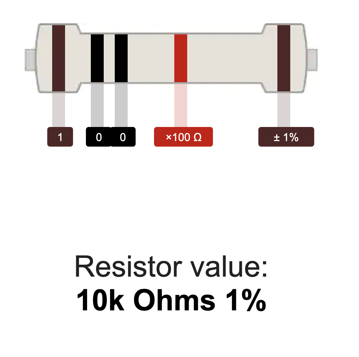
R4: 10 kΩ Resistor
R5: 180 Ω Resistor
R6: 100 kΩ Resistor
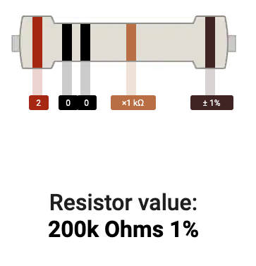
R7: 200 kΩ Resistor
 |  |  |  |
 |  |  |
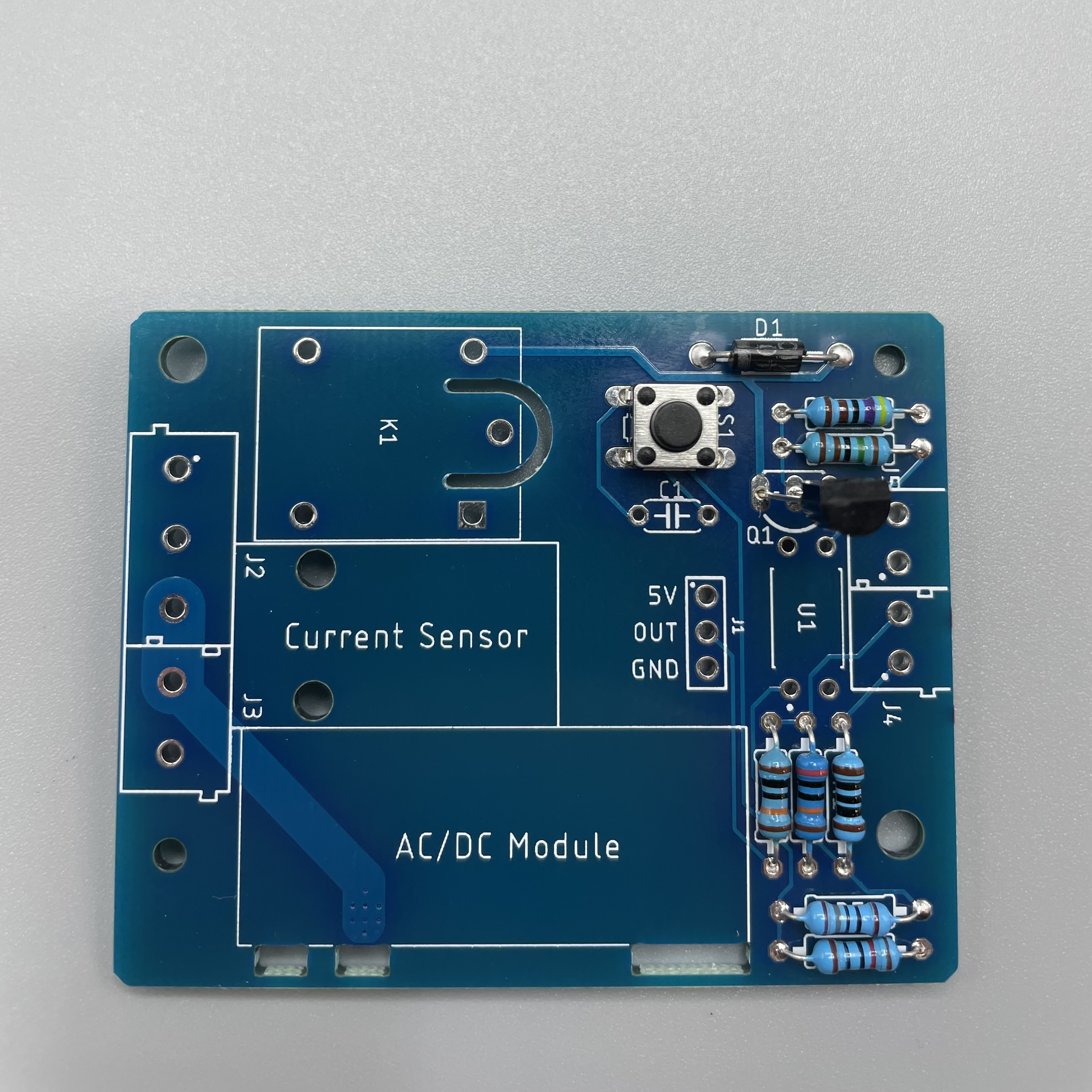
Next we solder the button on S1.
Solder the Transistor NPN on Q1.
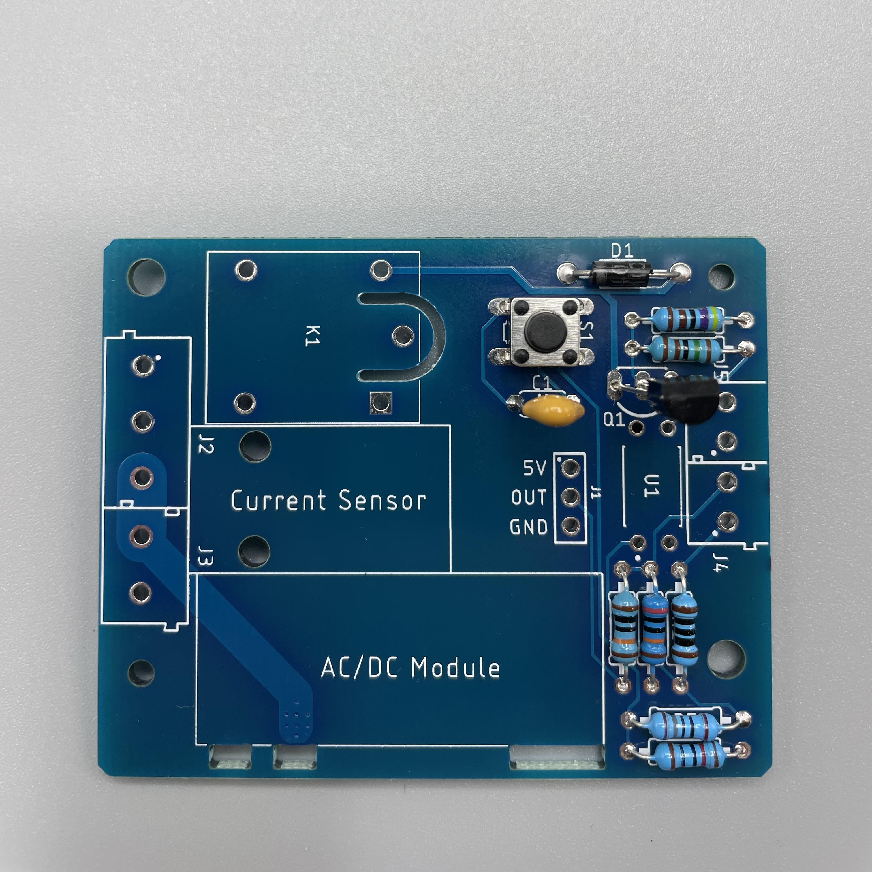
Solder the capacitor on C1.
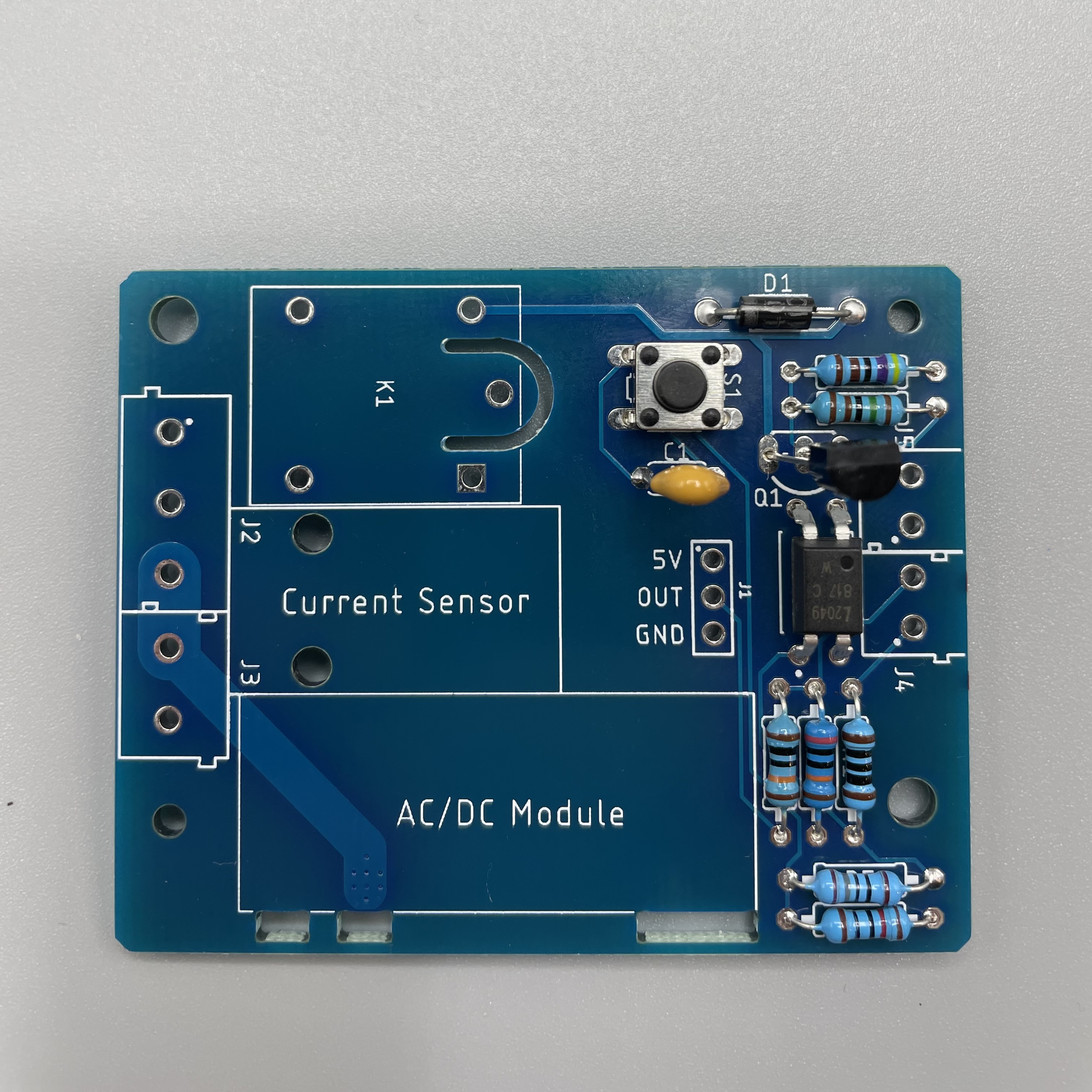
Solder the octocoupler on U1.
Solder the pin header on J1. Make sure the longer side faces upwards.
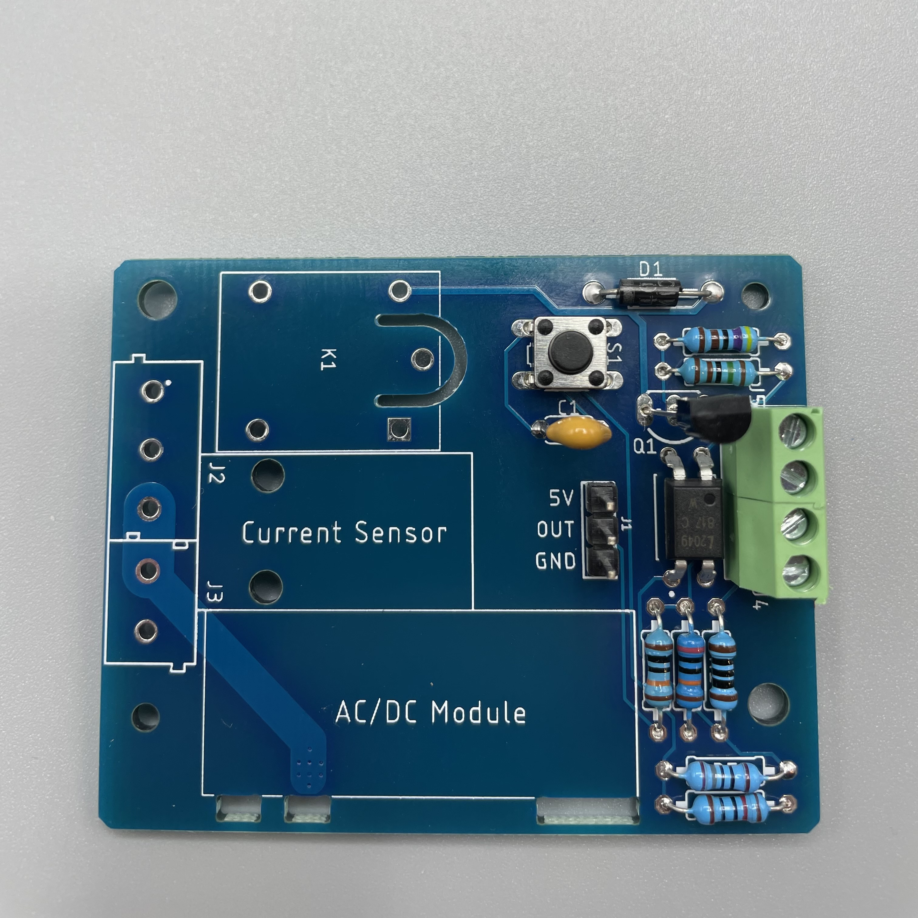
First stick both green terminal together by sliding them into each other. Then solder them on J4 and J5.
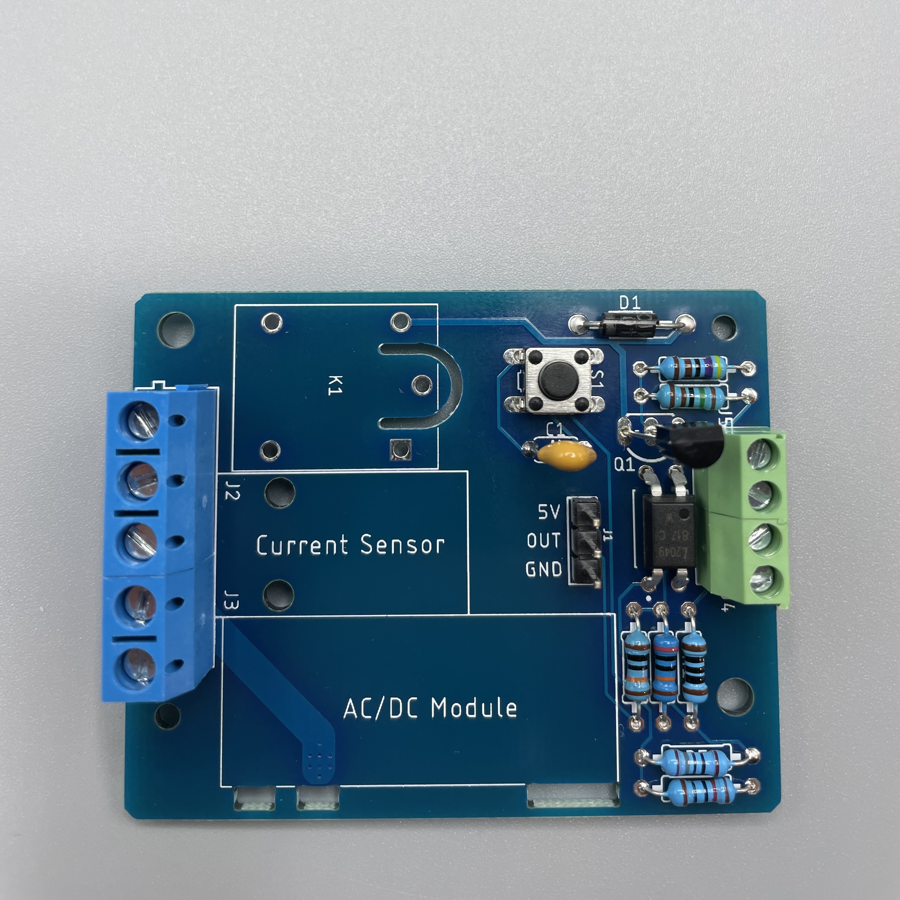
Stick the blue terminals together and solder them on J2 and J3.
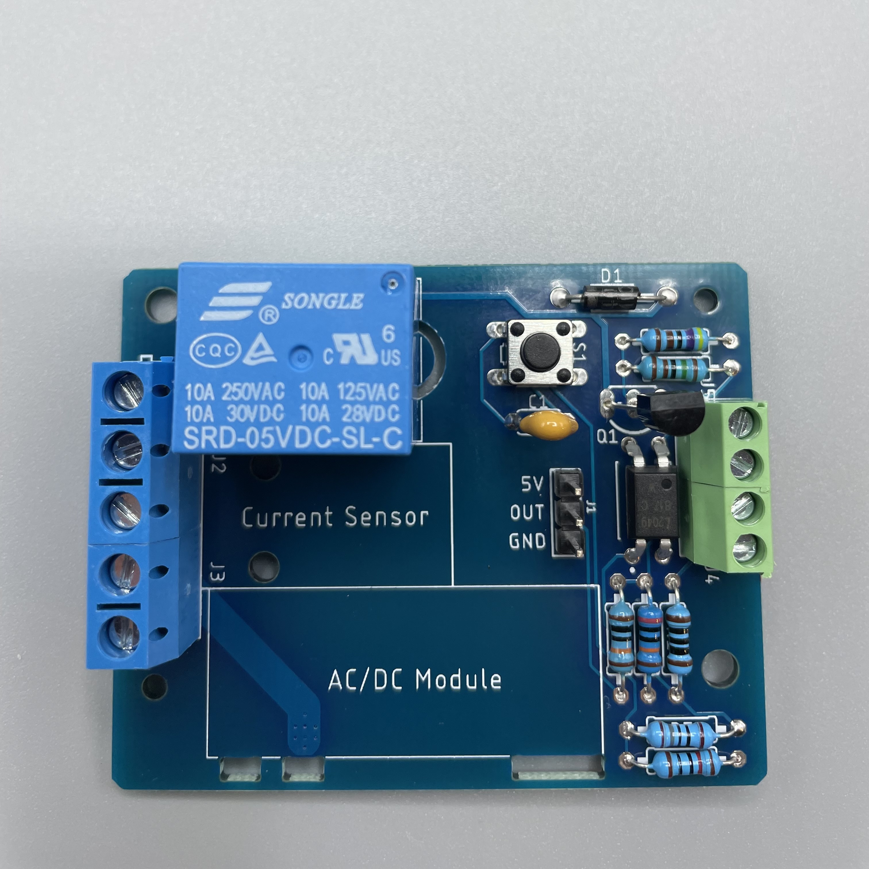
Get the relay and solder it on K1.
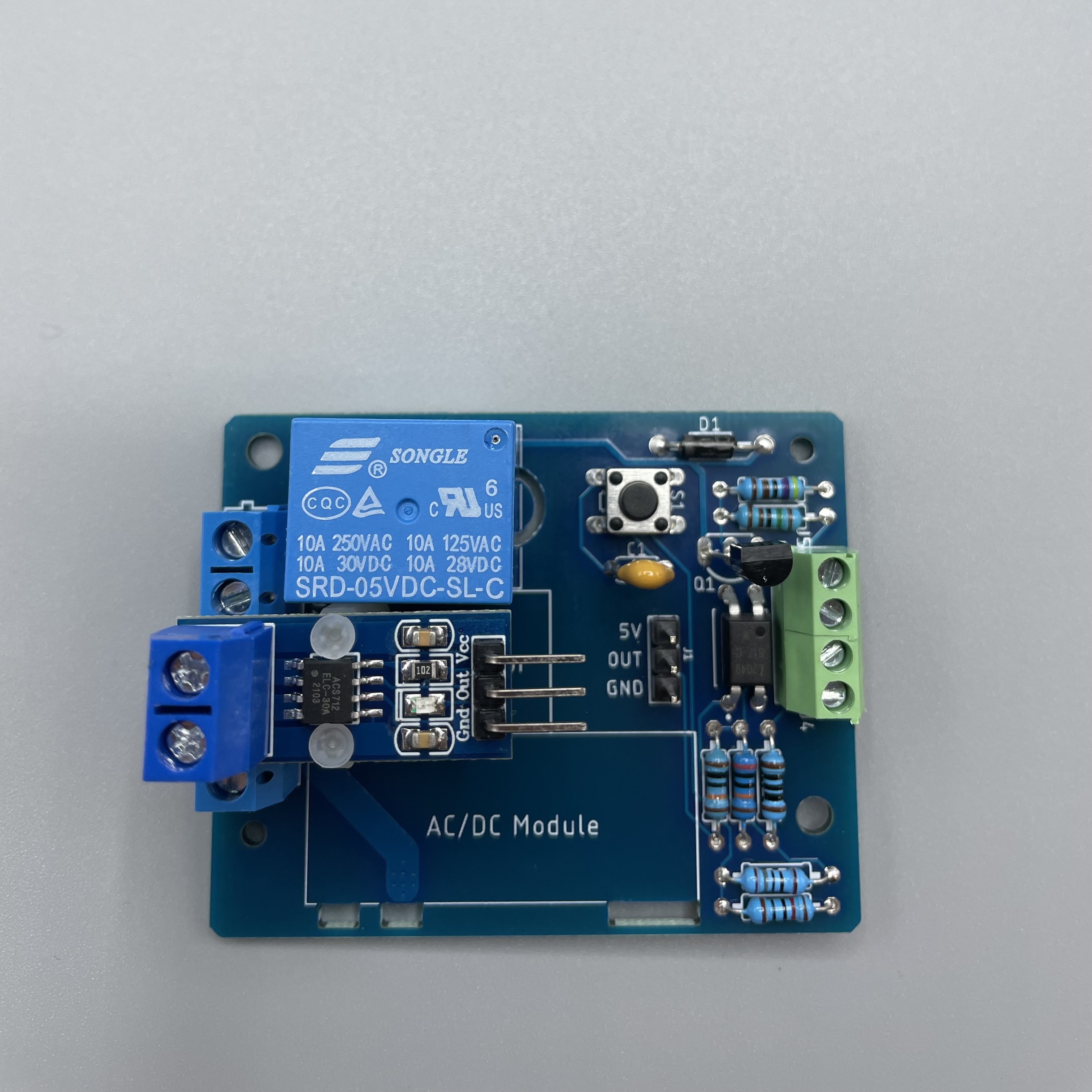
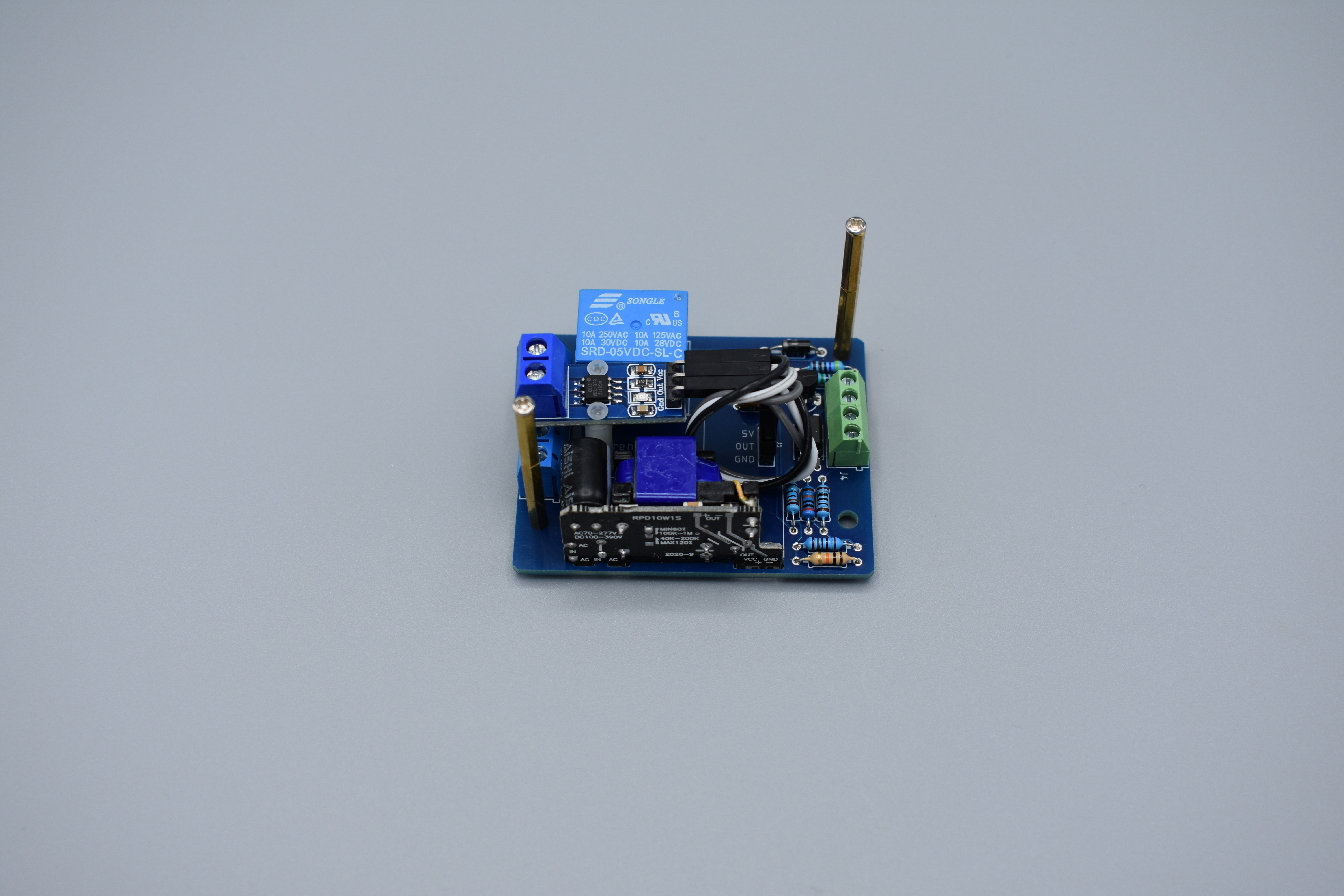
Use the M2 standoff plastic and the M2 screw plastic and screw them in at the current sensor.
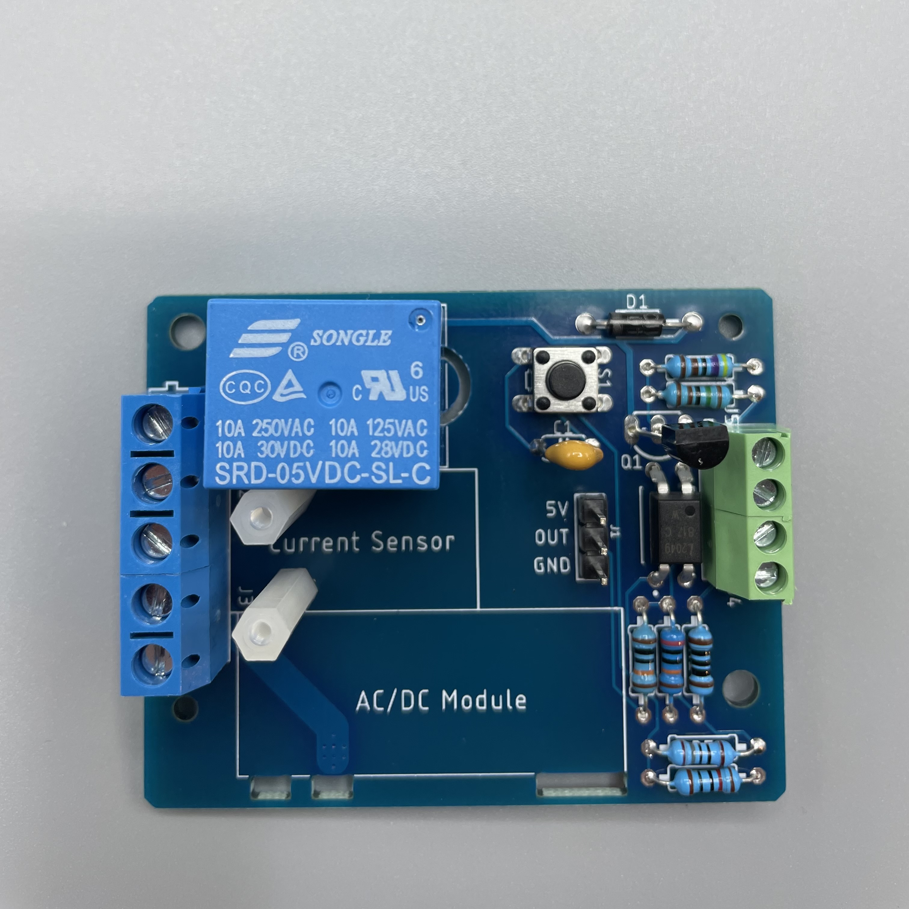
Put the current sensor on top and screw it in with the last two plastic screws.
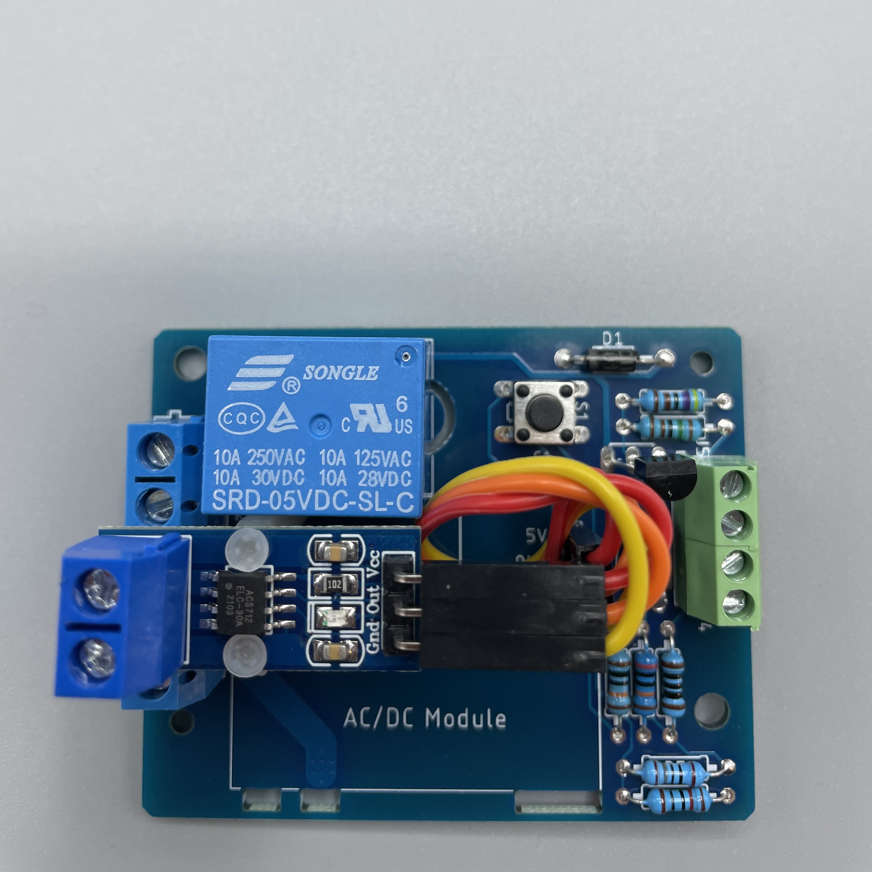
Now connect the pin header with the current sensor by using the three jumper wires. It should look like this.
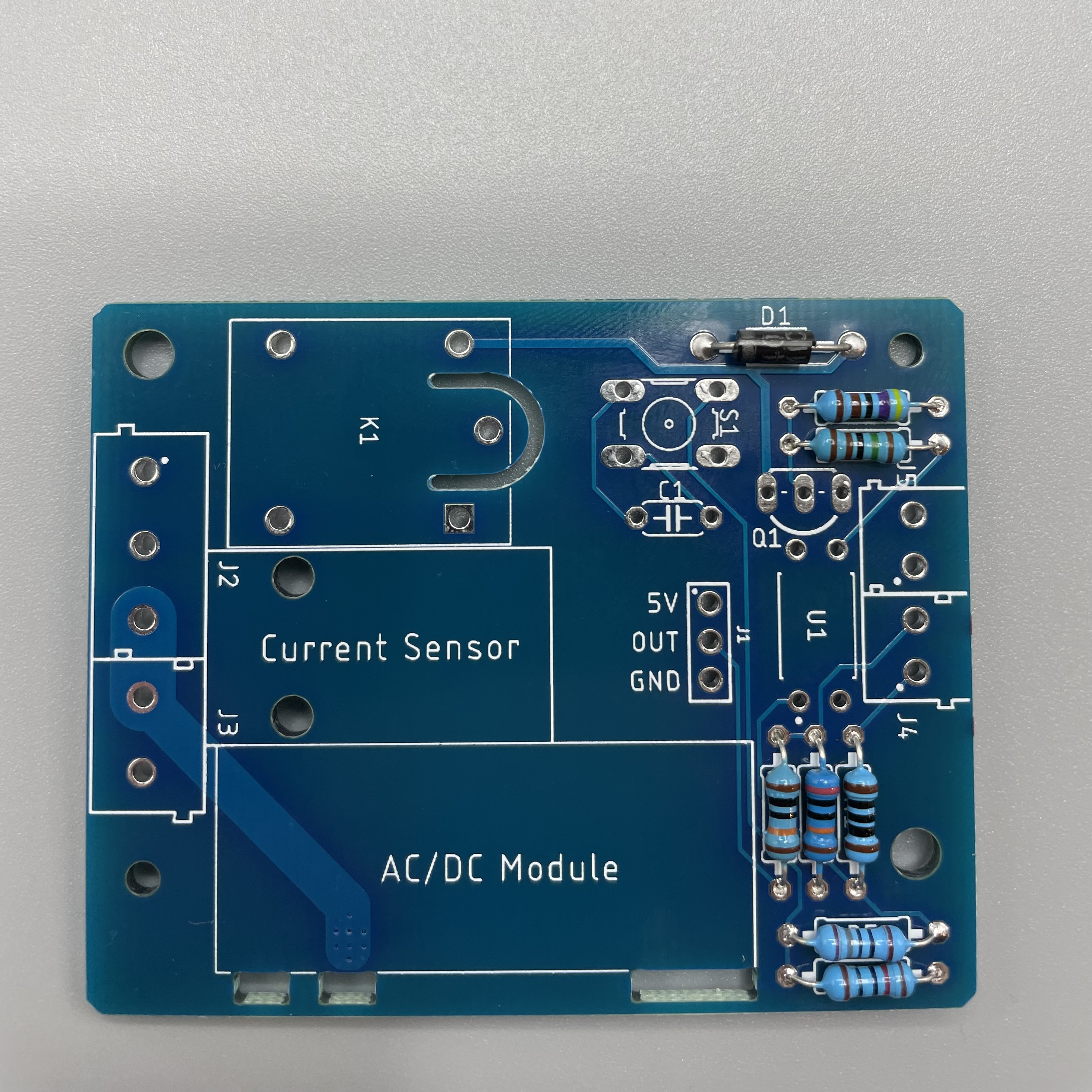
Lastly solder the AC/DC Module.
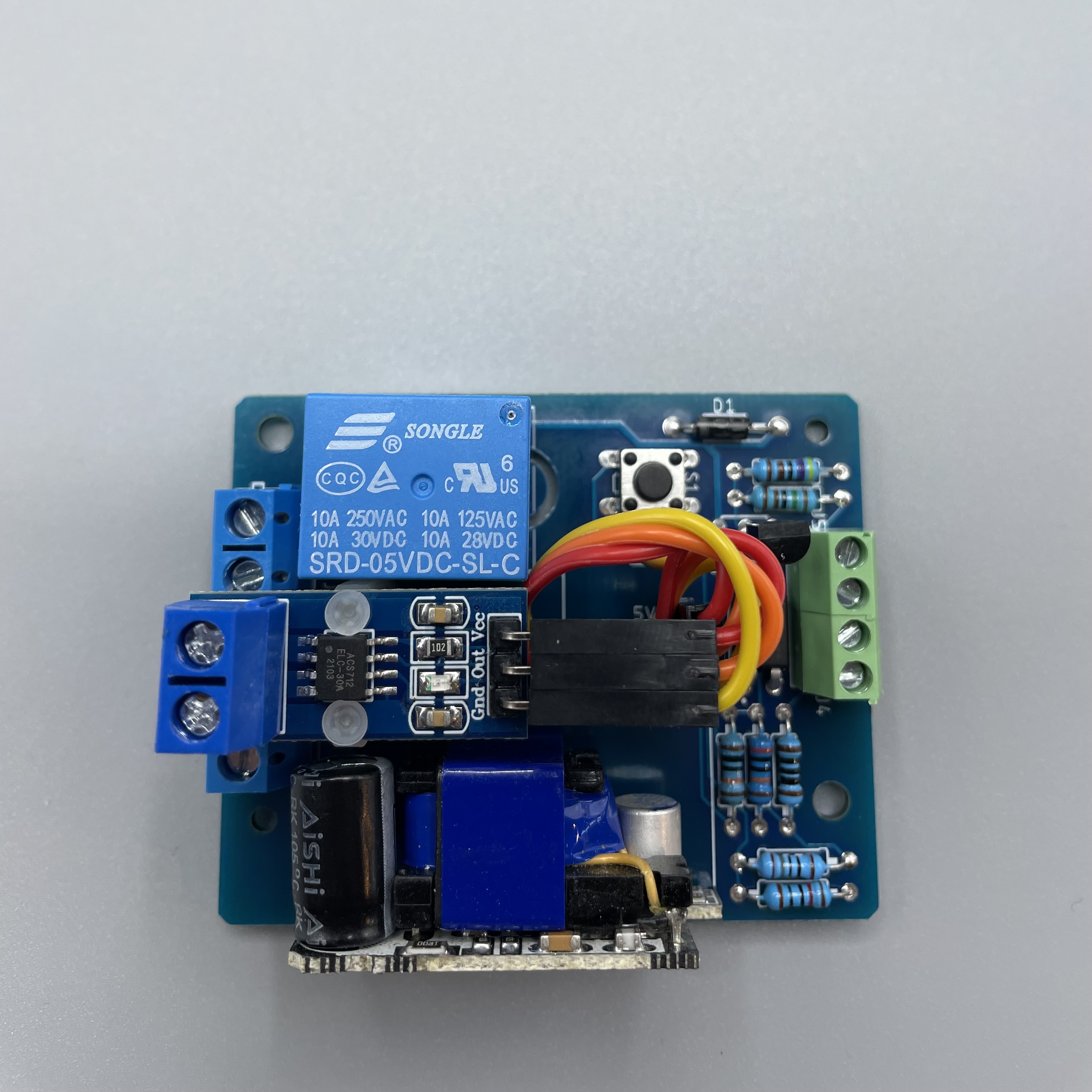
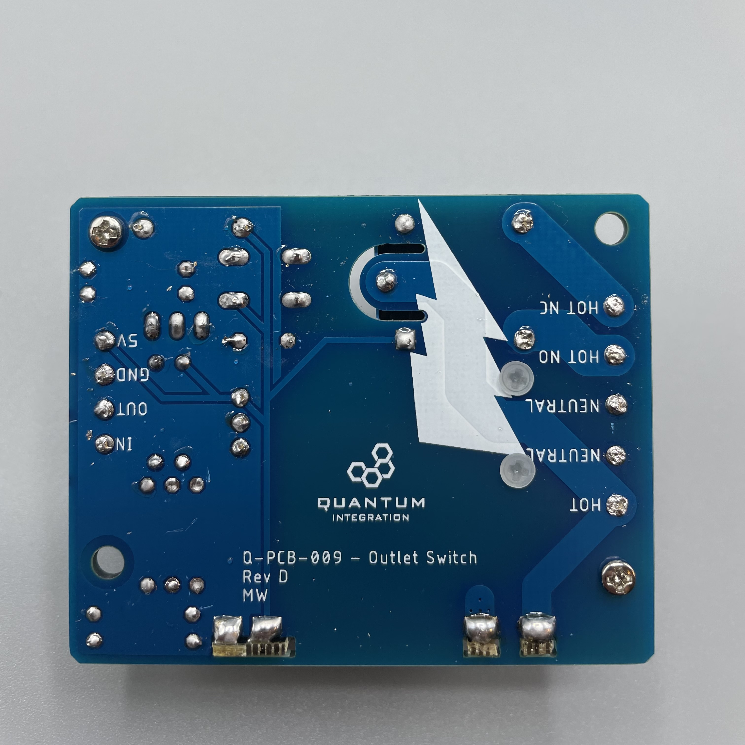
Your Outlet Switch DIY Kit is now ready to be used! The back should look like this.
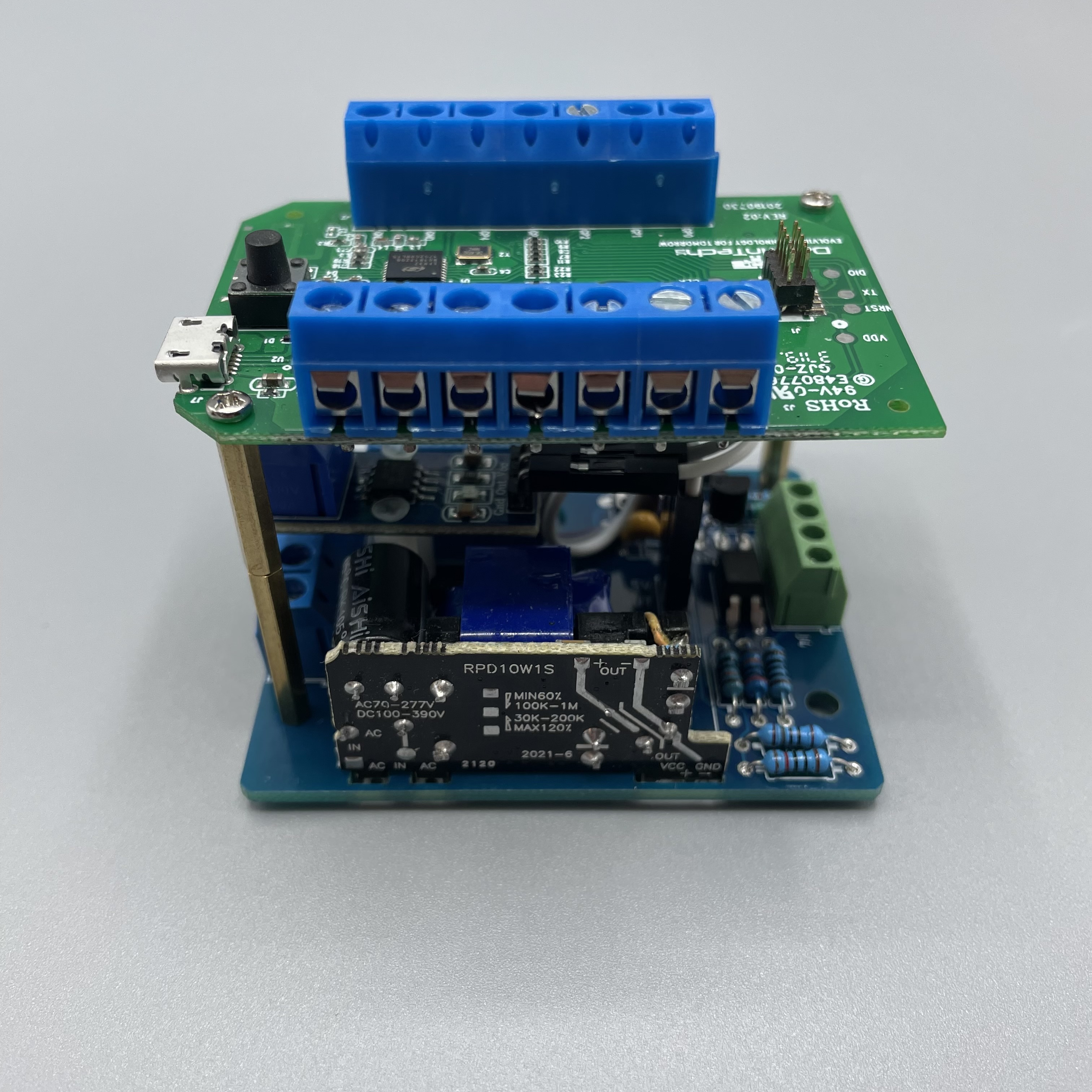
Using the metal standoffs you can screw a “stripped” Builder Base on top of the outlet switch.
Connecting to the Builder Base
Please refer to the following image on how to connect the DIY Kit to the Builder Base.

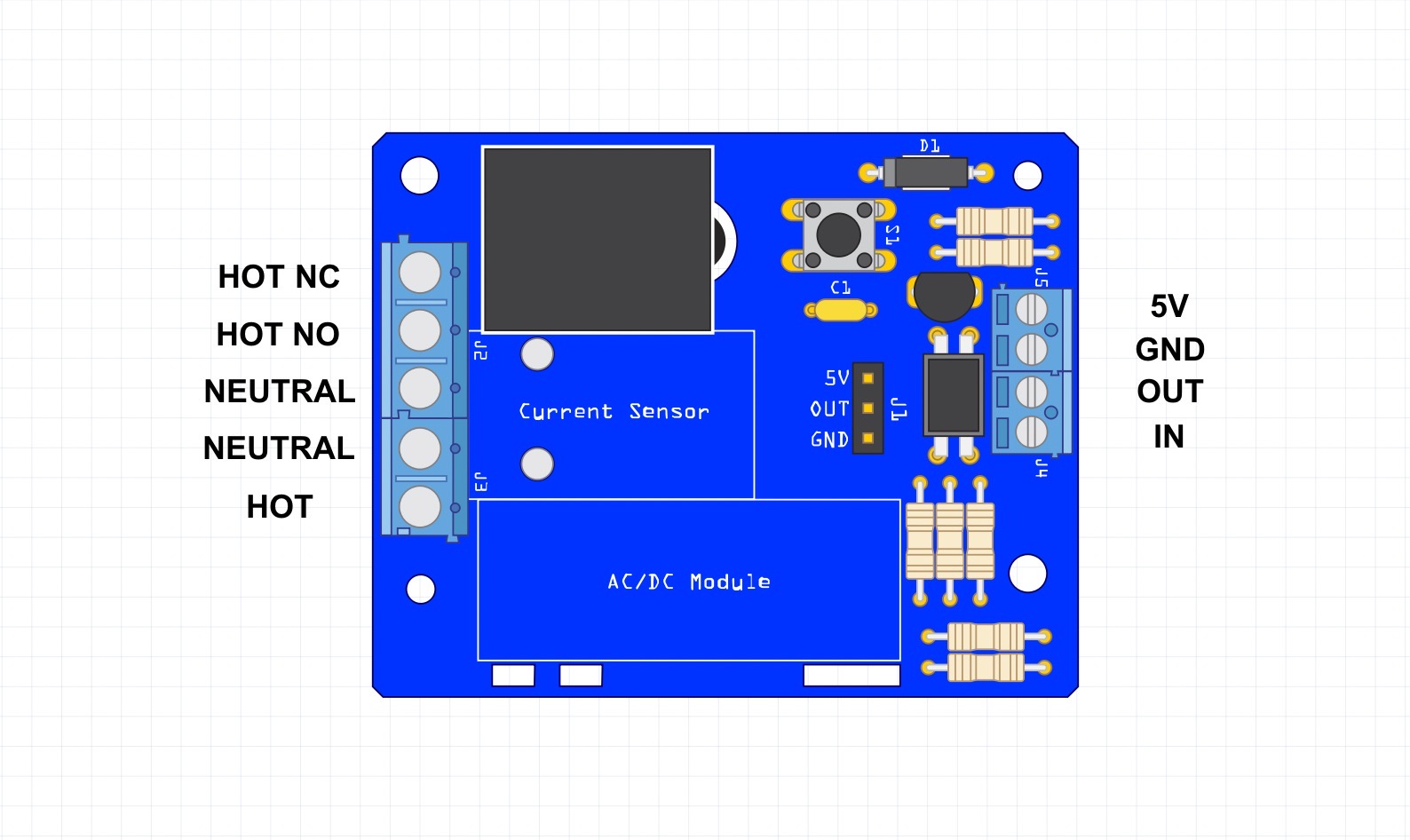
HOT NC: (NC = Normally closed) outputs Terminal 5 (HOT) DC or ACHOT input, when relay is actuated
HOT NO: (NO = Normally open) outputs Terminal 5 (HOT)HOT input, when relay is not actuated
NEUTRAL: Passthrough of HOT NONEUTRAL Input
NEUTRAL: NEUTRAL Input (5V Power Supply)
HOT Input: AC/DC input
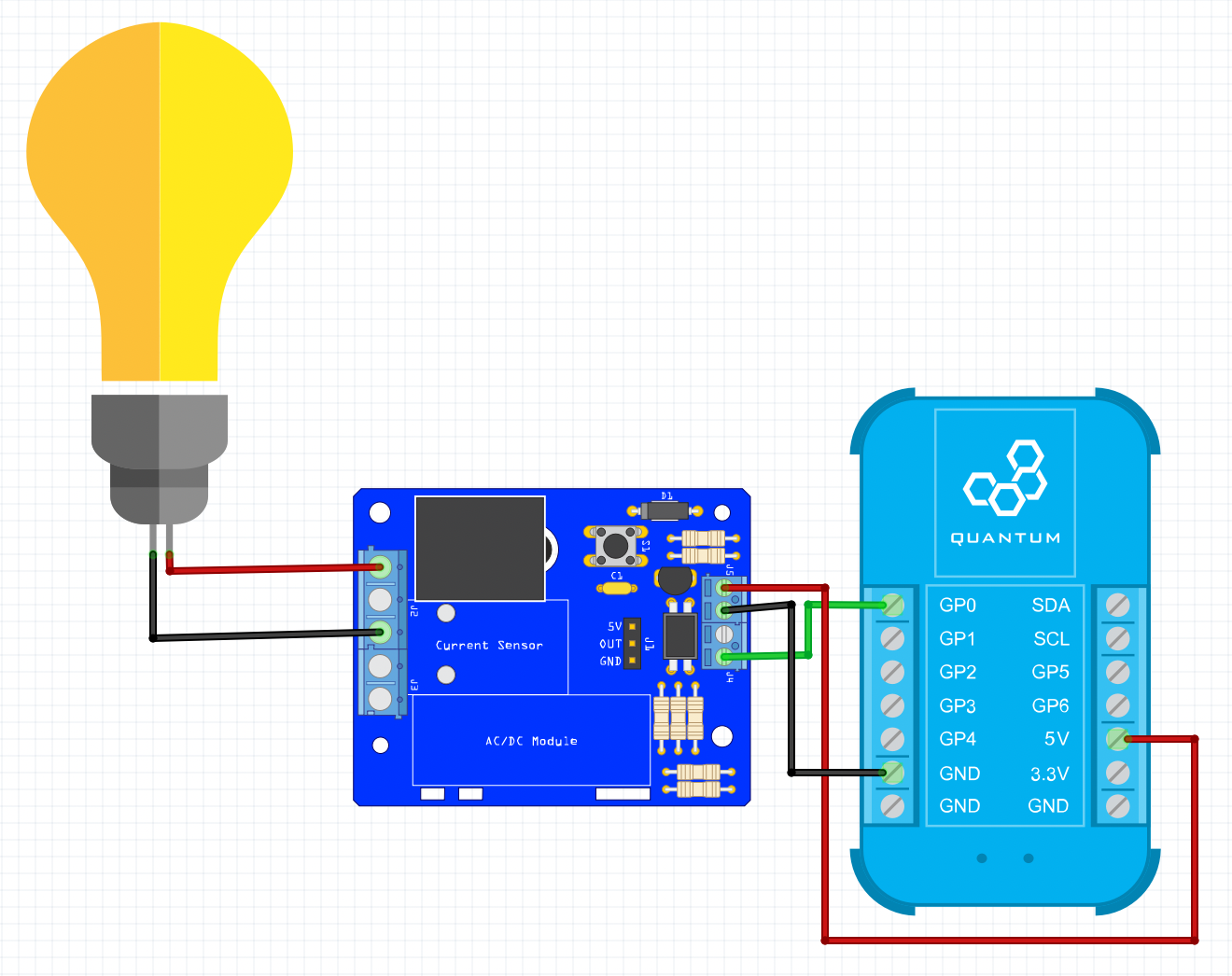

The Outlet Switch will allow you to switch any device that is connected to the outlet on and off like a lamp or a TV for instance. It can give you your energy usage data through the current sensor that sits on top of the DIY Kit. The Builder Base will be powered trough the Outlet Switch. The button on the Outlet Switch turns your project on and off or you can use your mobile app on your smartphone to do so.
Unfortunately the ACS712 current sensing board is not supported but will be shortly in the future.
Projects
Gallery
Resources
App & Firmware
|
|
This DIY Kit page is currently optimized for revision D.
Current revision
Assembly files for the current revision of the DIY Kit (Rev D): | https://github.com/QuantumIntegration/Q-PCB-009-Outlet-Switch-Hardware-Files |
|---|
Older revisions
- | - |
|---|