| Table of Contents |
|---|
Overview
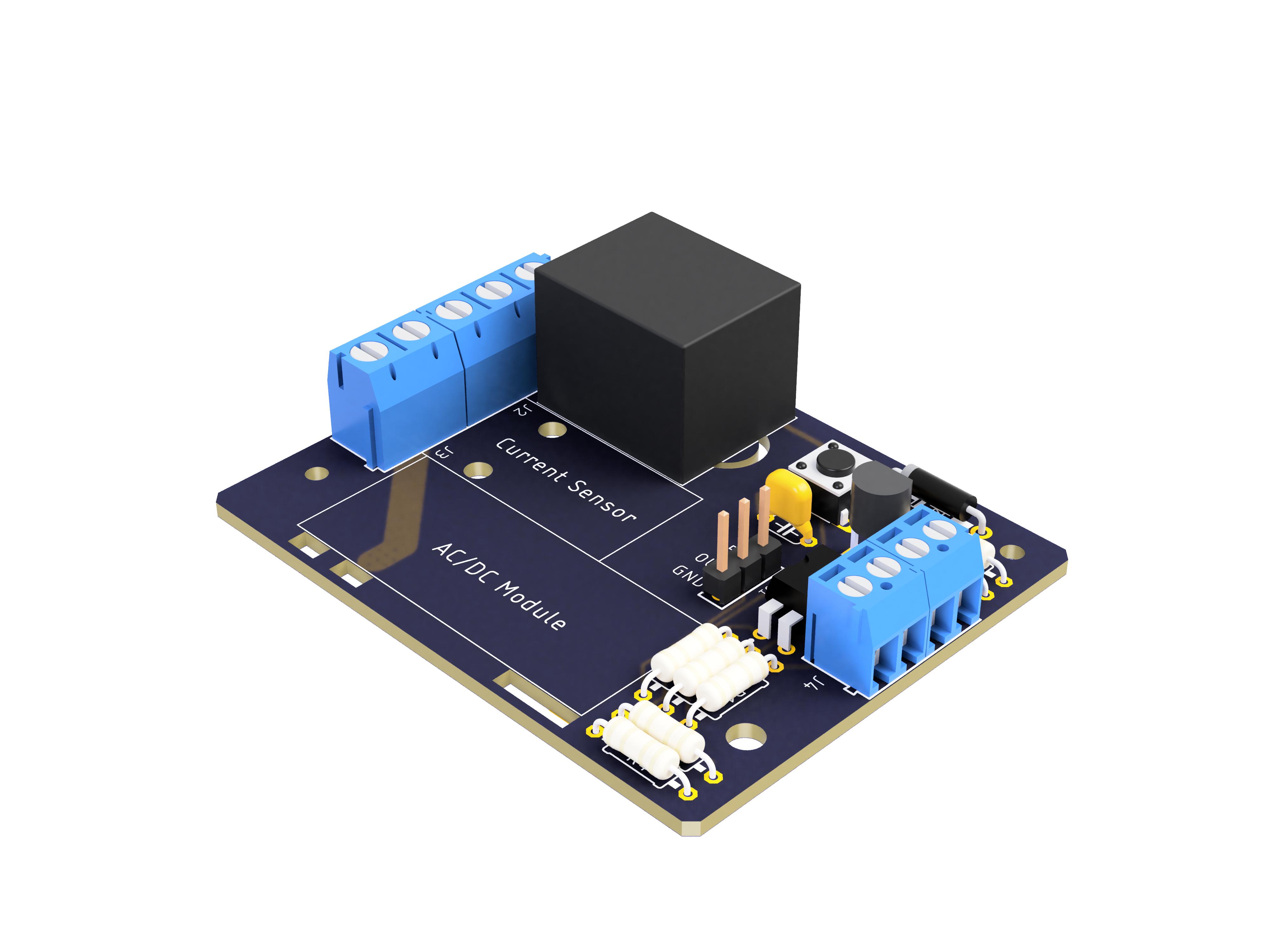
The Outlet Switch DIY Kit can control the power of an outlet with the Quantum platform. An outgrowth of Quantum’s Smart Outlet project, this kit is wired to a Builder Base and outlet and can fit into a standard outlet box. It takes in up to 240V AC or 30V DC at 10 amps, and uses a relay switch to power the outlet on/off. This allows you to control the power of an outlet from the Quantum dashboard on any smart device or with a trigger component like a pushbutton on the IR remote.
|
|
Hardware Components
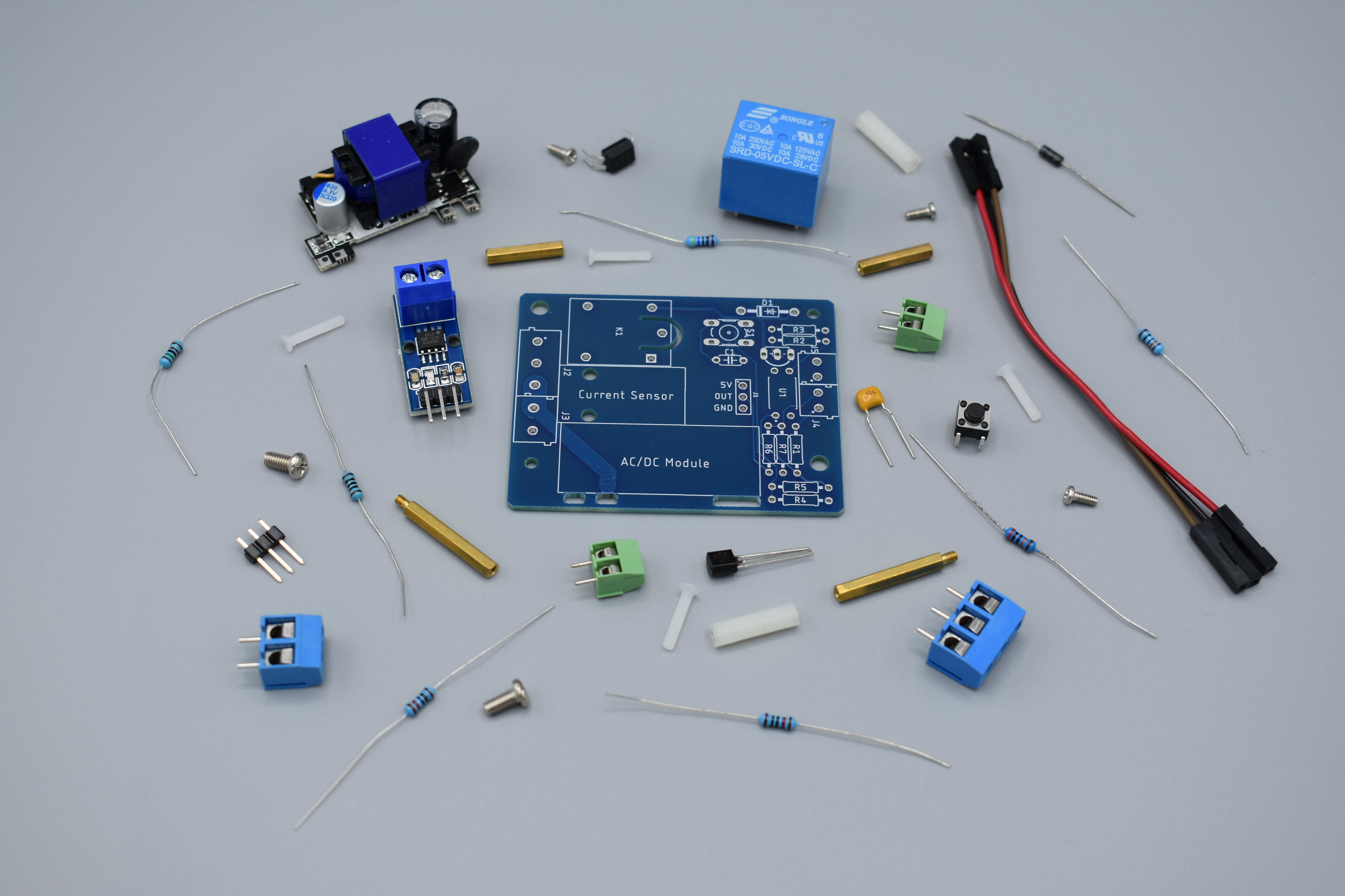
The components are part of the DIY Kit or can be sourced separately with help of the BOM:
| View file | ||
|---|---|---|
|
Picture | Name | Designator | Quantity |
|---|---|---|---|
Reads: “104” | 100nf Capacitor | C1 | 1 |
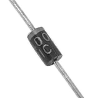 | 1N4000 Diode | D1 | 1 |
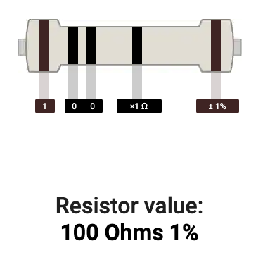 | 100 Ω Resistor | R1 | 1 |
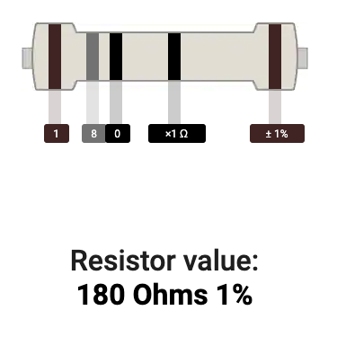 | 180 Ω Resistor | R5 | 1 |
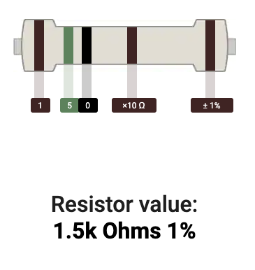 | 1.5 kΩ Resistor | R2 | 1 |
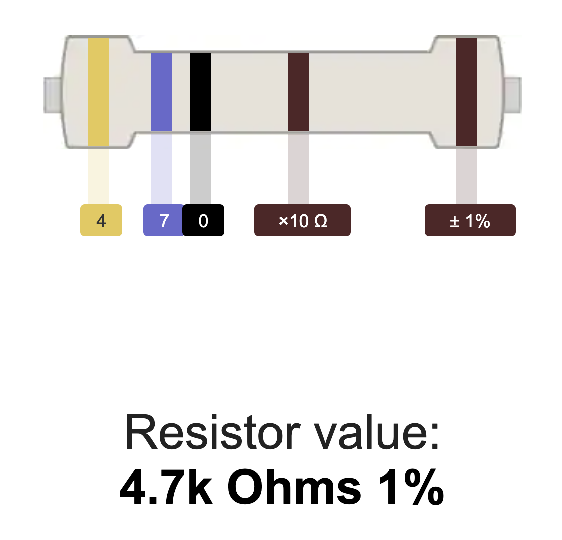 | 4.7 kΩ Resistor | R3 | 1 |
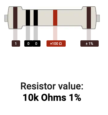 | 10 kΩ Resistor | R4 | 1 |
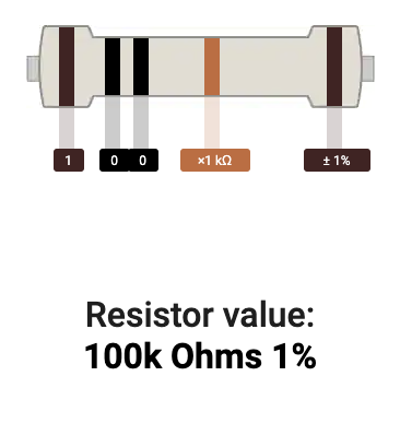 | 100 kΩ Resistor | R6 | 1 |
 | 200 kΩ Resistor | R7 | 1 |
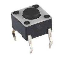 | Tactile Push Button | S1 | 1 |
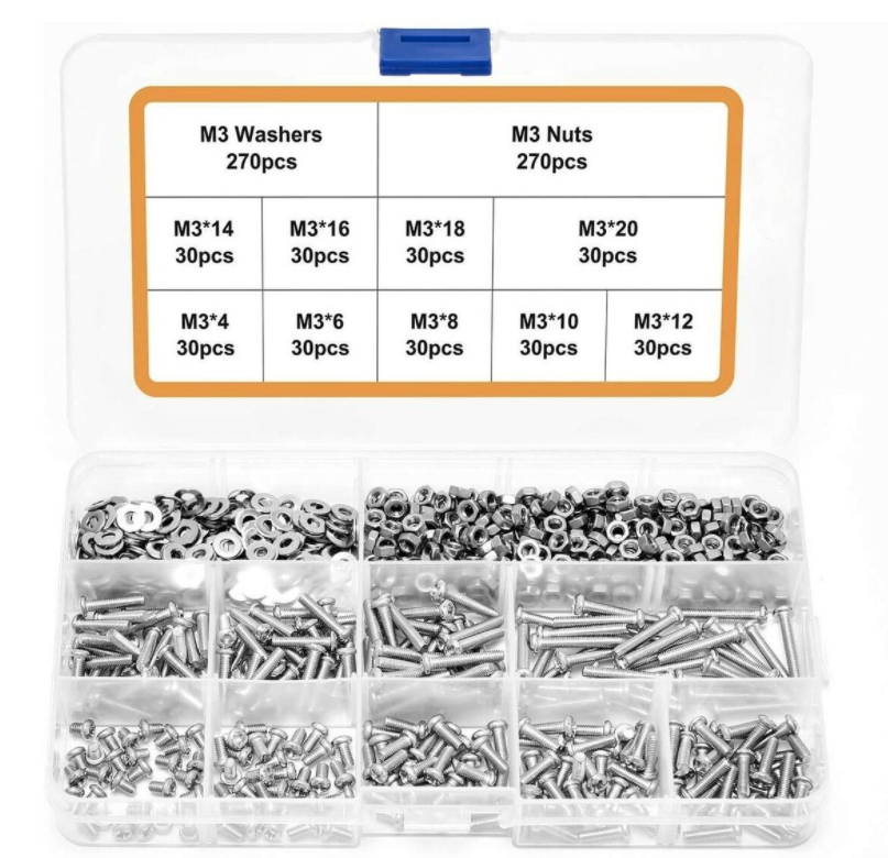 | Mounting Hardware
| 18 | |
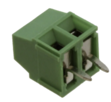
 | Terminal | J2, J3 | 2 1/2 |
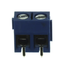
 | 1x2 3.5mm Terminal Block | J4, J5 | 2 |
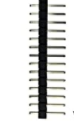 | 1x3 male pin header | J1 | 1 |
Transistor NPN | Q1 | 1 | |
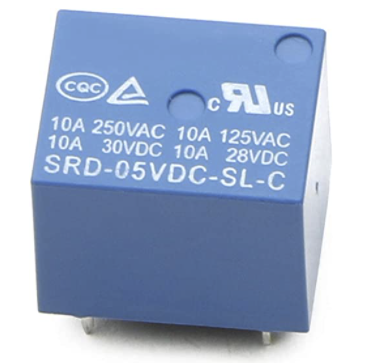 | Relay | K1 | 1 |
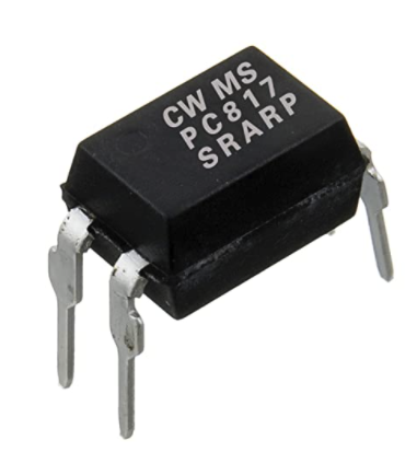 | Octocoupler | U1 | 1 |
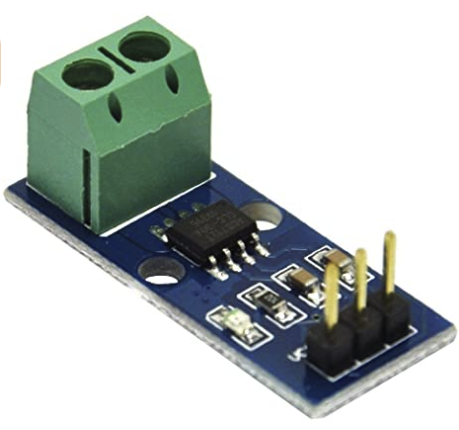 | Current Sensor | 1 | |
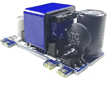 | Power Supply | 1 | |
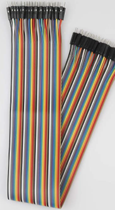 | Jumper Wires FF | 3 | |
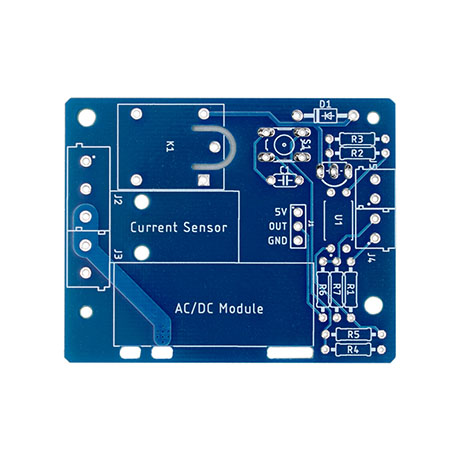 | Switched Outlet PCB | Q-PCB-007 | 1 |
Tools Used
Picture | Name | Quantity | Link |
|---|---|---|---|
Small flat-head screwdriver | 1 | Included in Component Kit or you can pick from one on our Recommended Tools List | |
Soldering Iron | 1 | You can pick from one on our Recommended Tools List | |
Solder | 1 | You can pick from one on our Recommended Tools List | |
Diagonal Cutters | 1 | You can pick from one on our Recommended Tools List | |
Work Holder | 1 | You can pick from one on our Recommended Tools List |
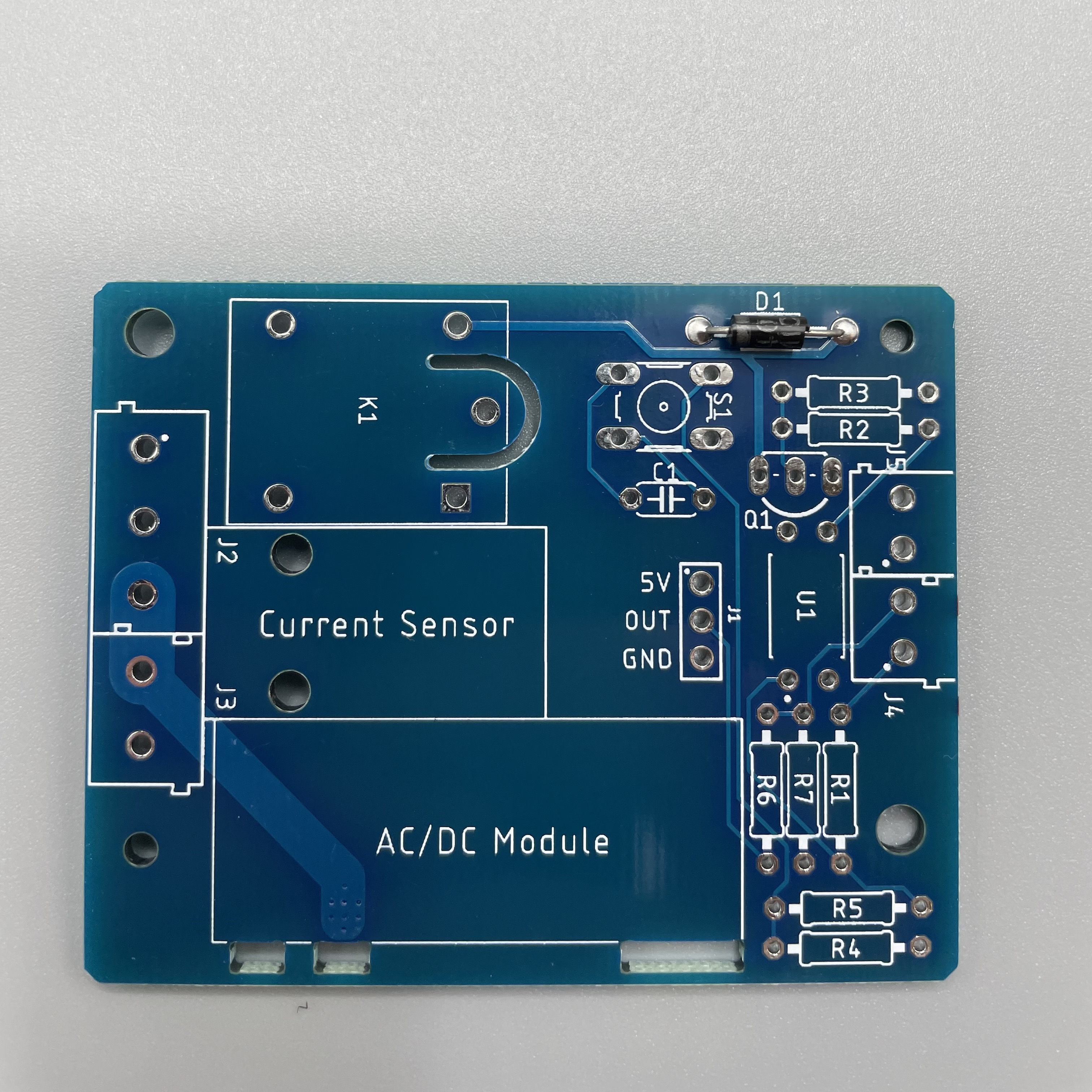
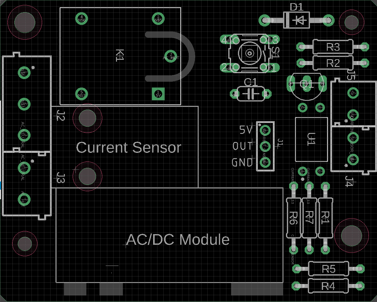
PCB Assembly and Soldering
Place groups of components on the board and then solder them to the pads.
Using some form of work holder is advised. You can find a list of suitable work holders on our Recommended Tools List.

We will start by putting all the parts on the table.
If you are not familiar with soldering you should start with components with the lowest profile, like for example resistors and then move up to components like buttons with higher profile.
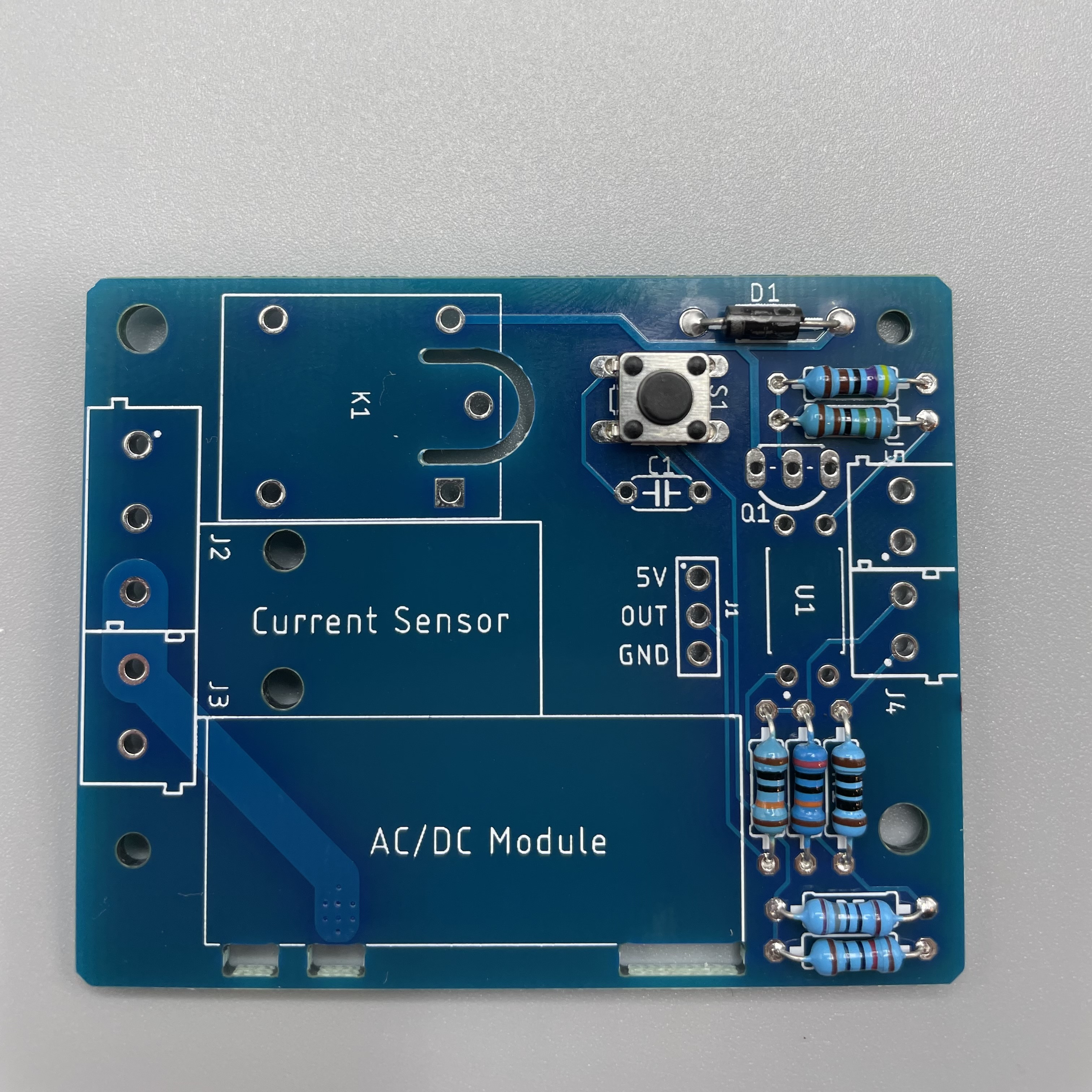
Solder the Diode on D1. Make sure it has the right direction.
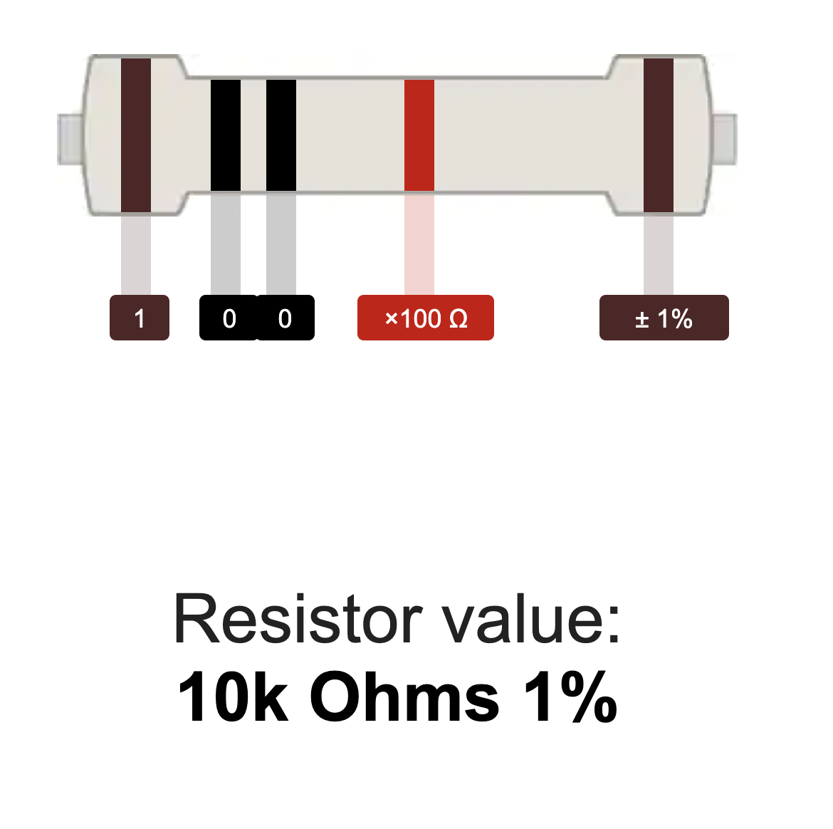
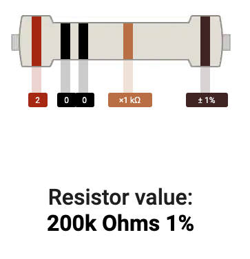
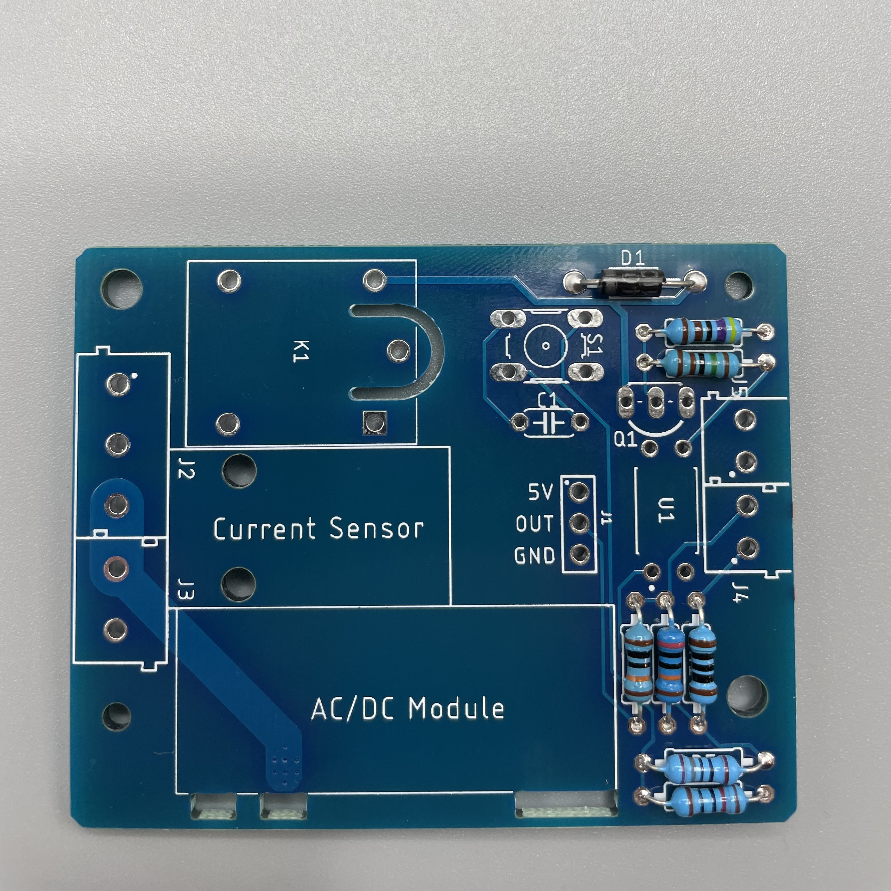
Next are the resistors. Use the table and pictures to identify them.
R1: 100 Ω Resistor
R2: 1.5 kΩ Resistor
R3: 4.7 kΩ Resistor
R4: 10 kΩ Resistor
R5: 180 Ω Resistor
R6: 100 kΩ Resistor
R7: 200 kΩ Resistor
 |  |  |  |
 |  |  |
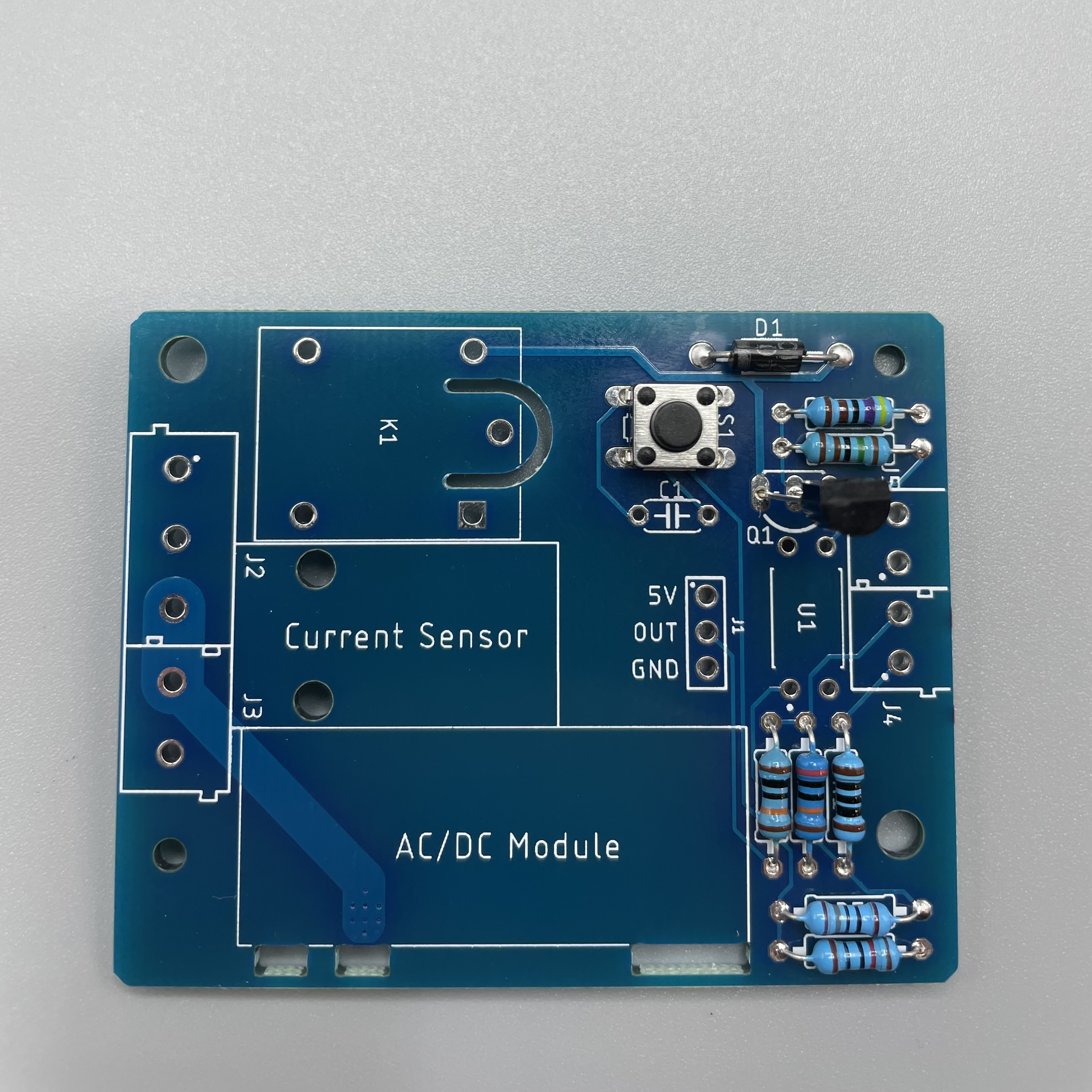
Next we solder the button on S1.
Solder the Transistor NPN on Q1.
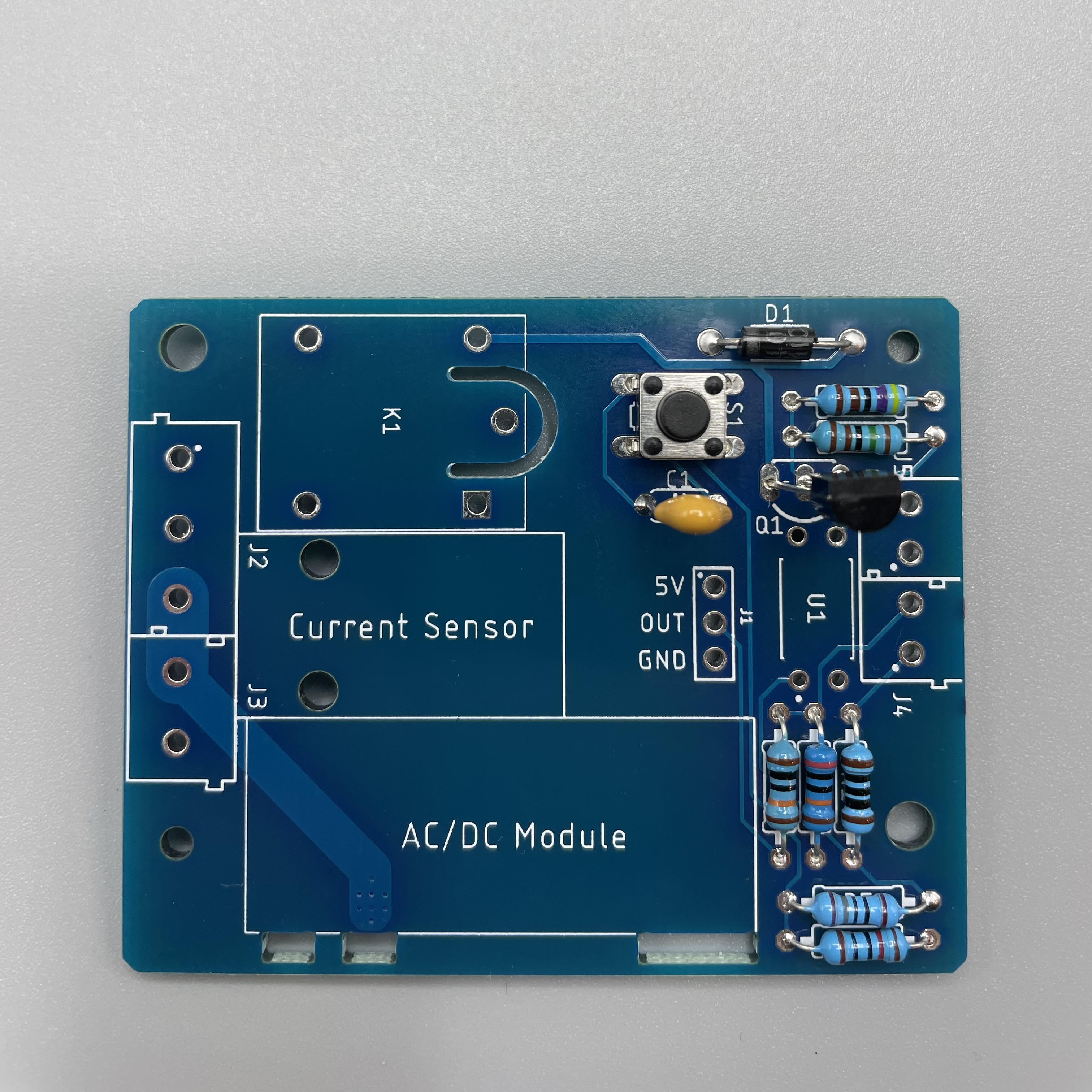
Solder the capacitor on C1.
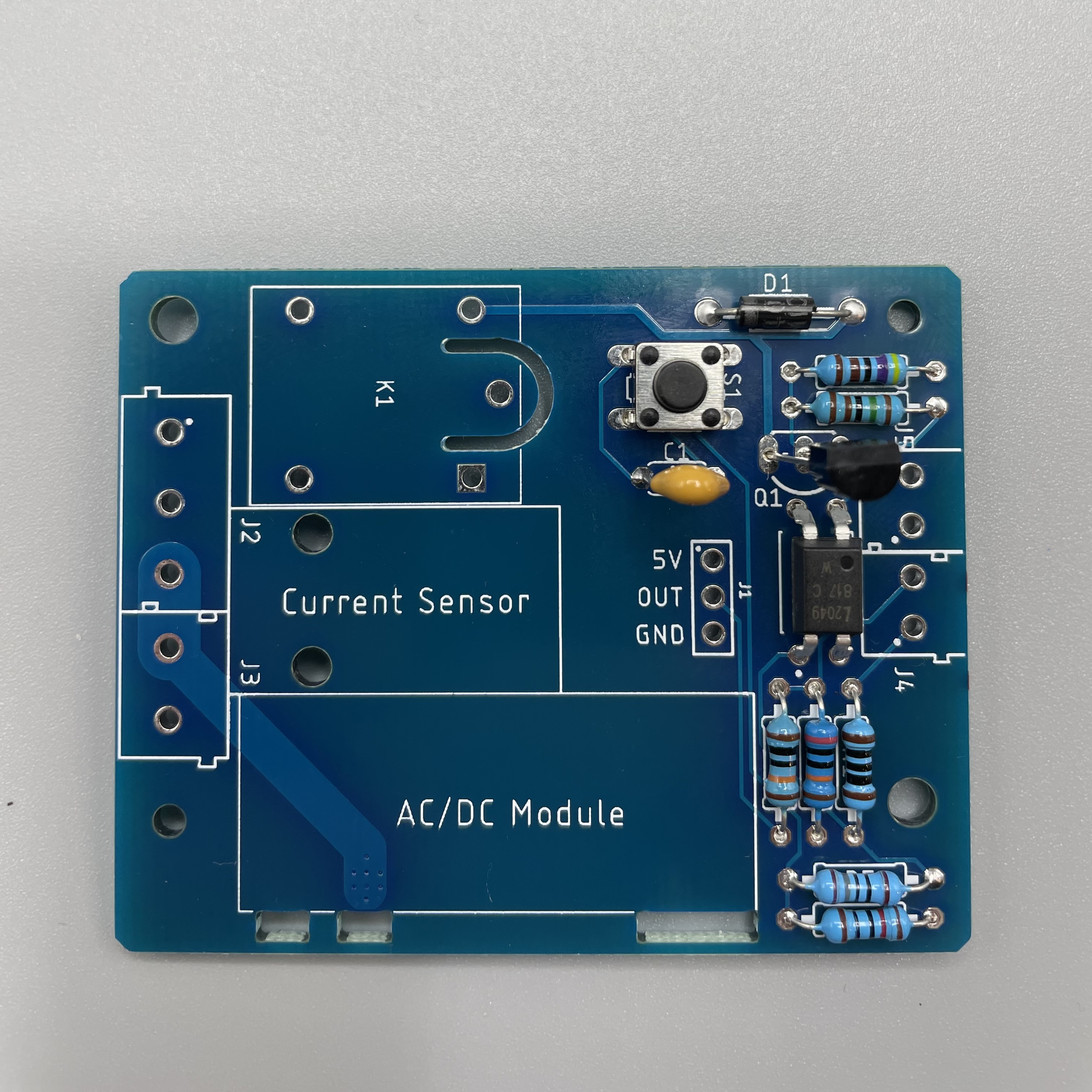
Solder the octocoupler on U1.
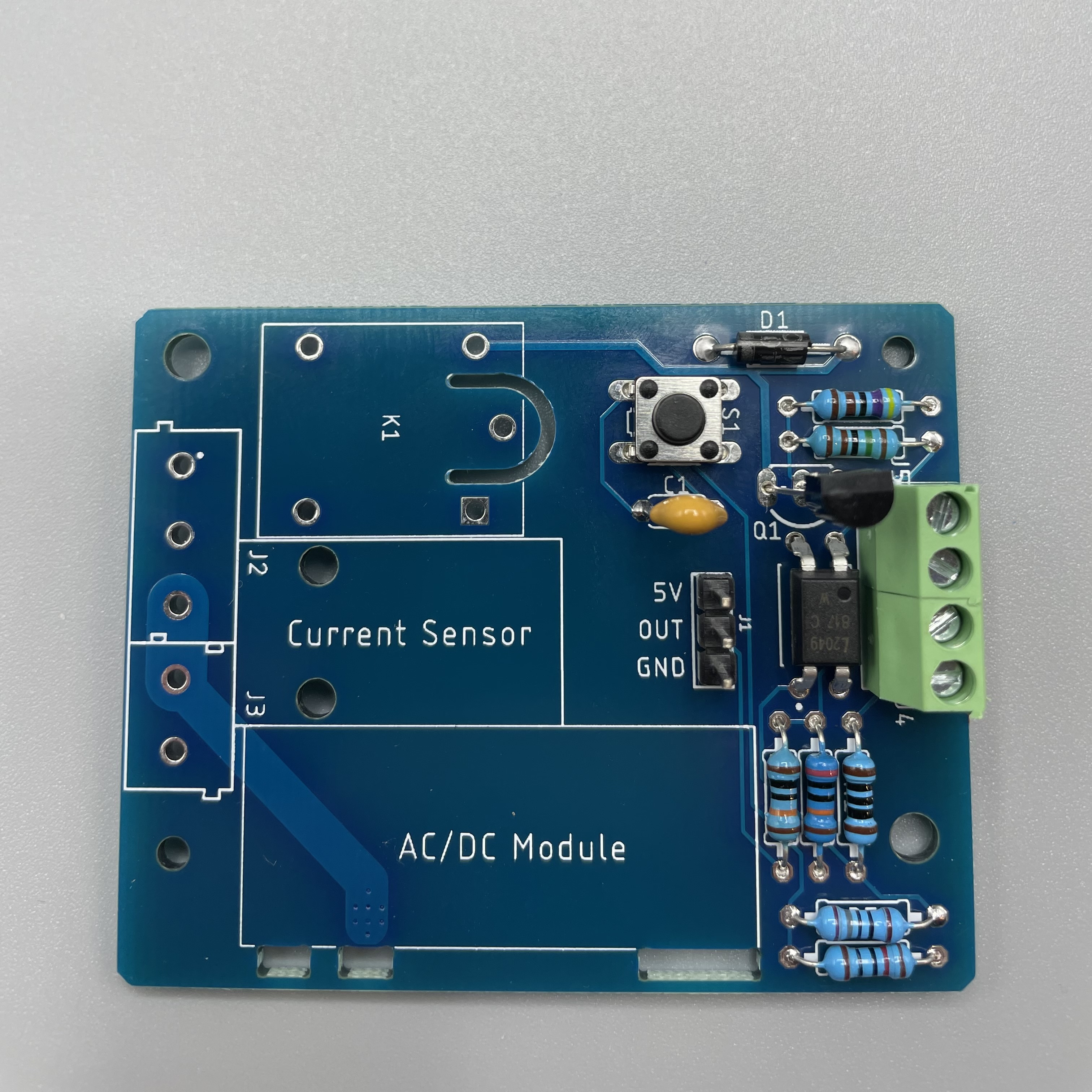
Solder the pin header on J1. Make sure the longer side faces upwards.
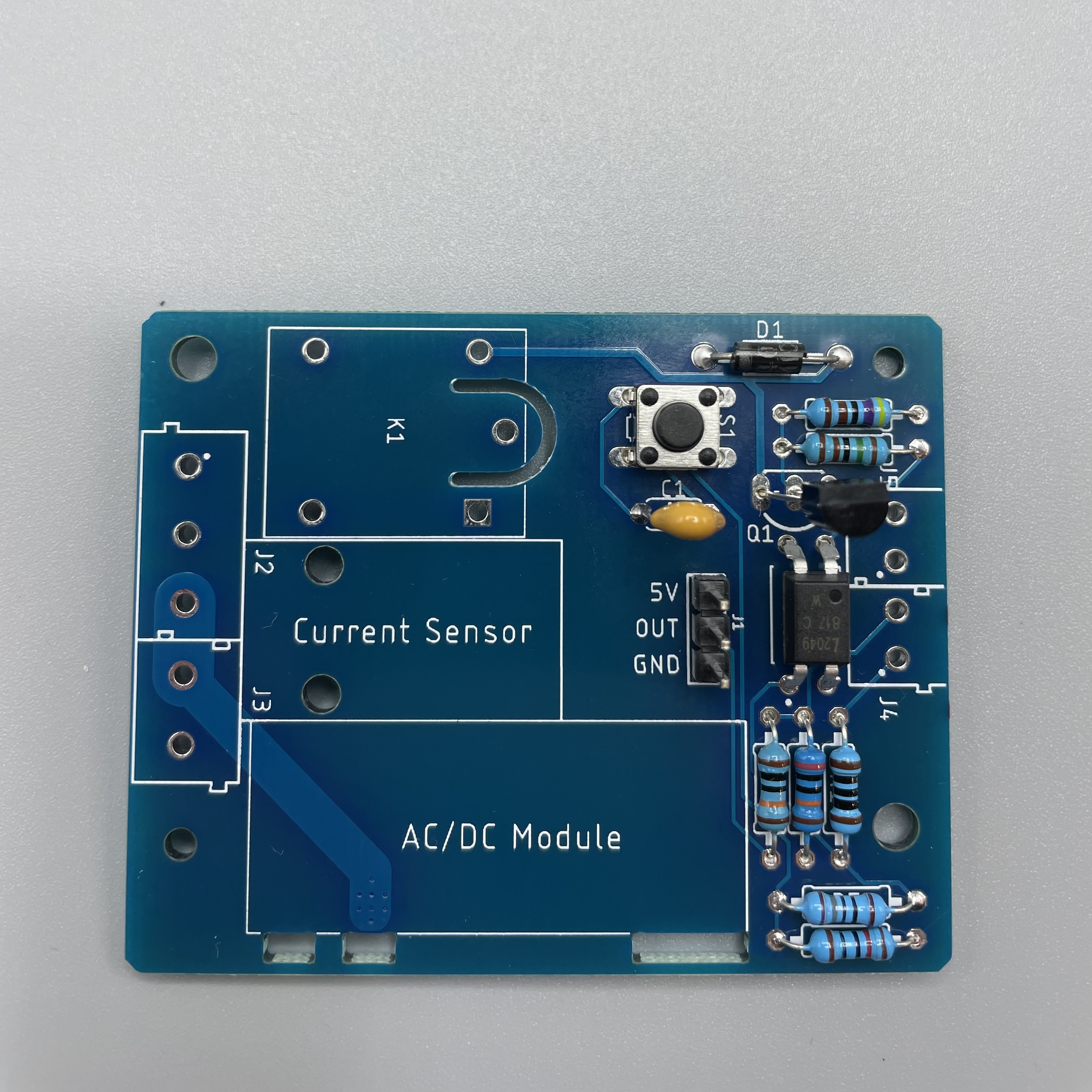
First stick both green terminal together by sliding them into each other. Then solder them on J4 and J5.
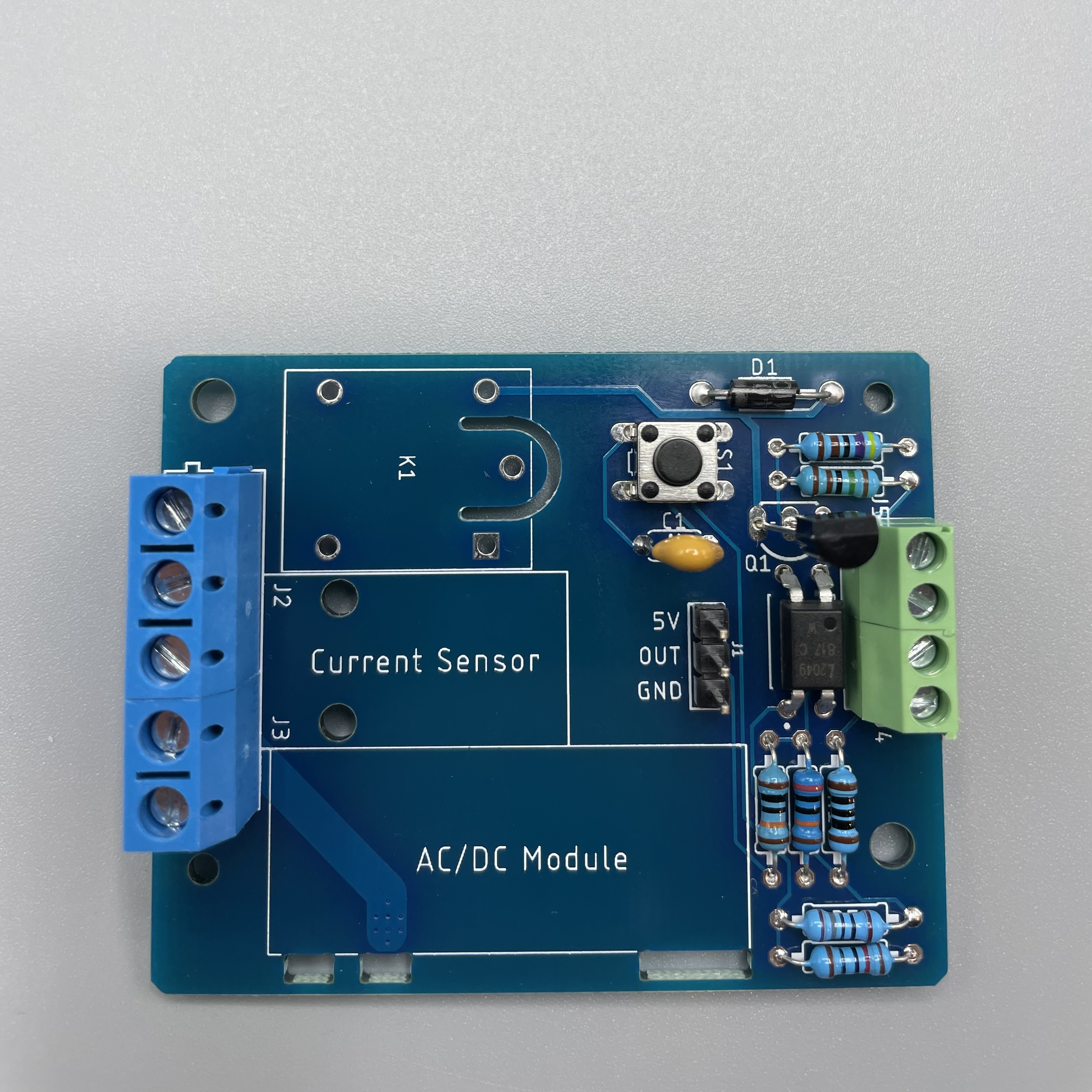
Stick the blue terminals together and solder them on J2 and J3.
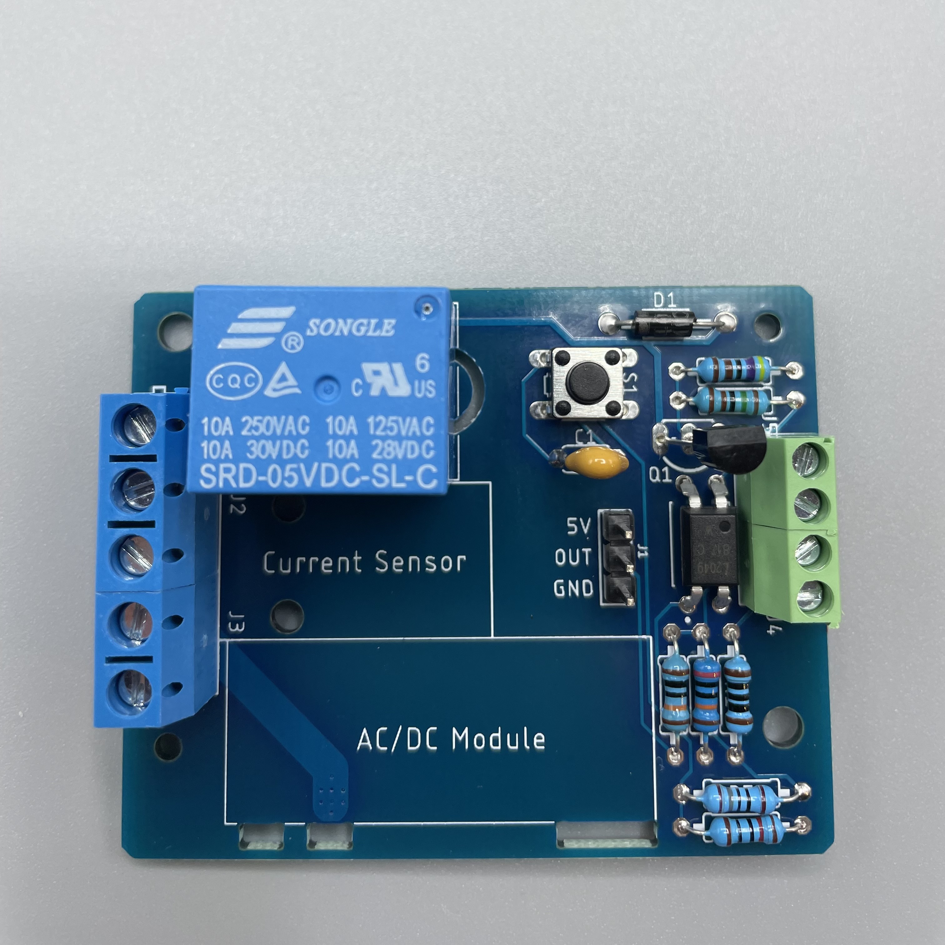
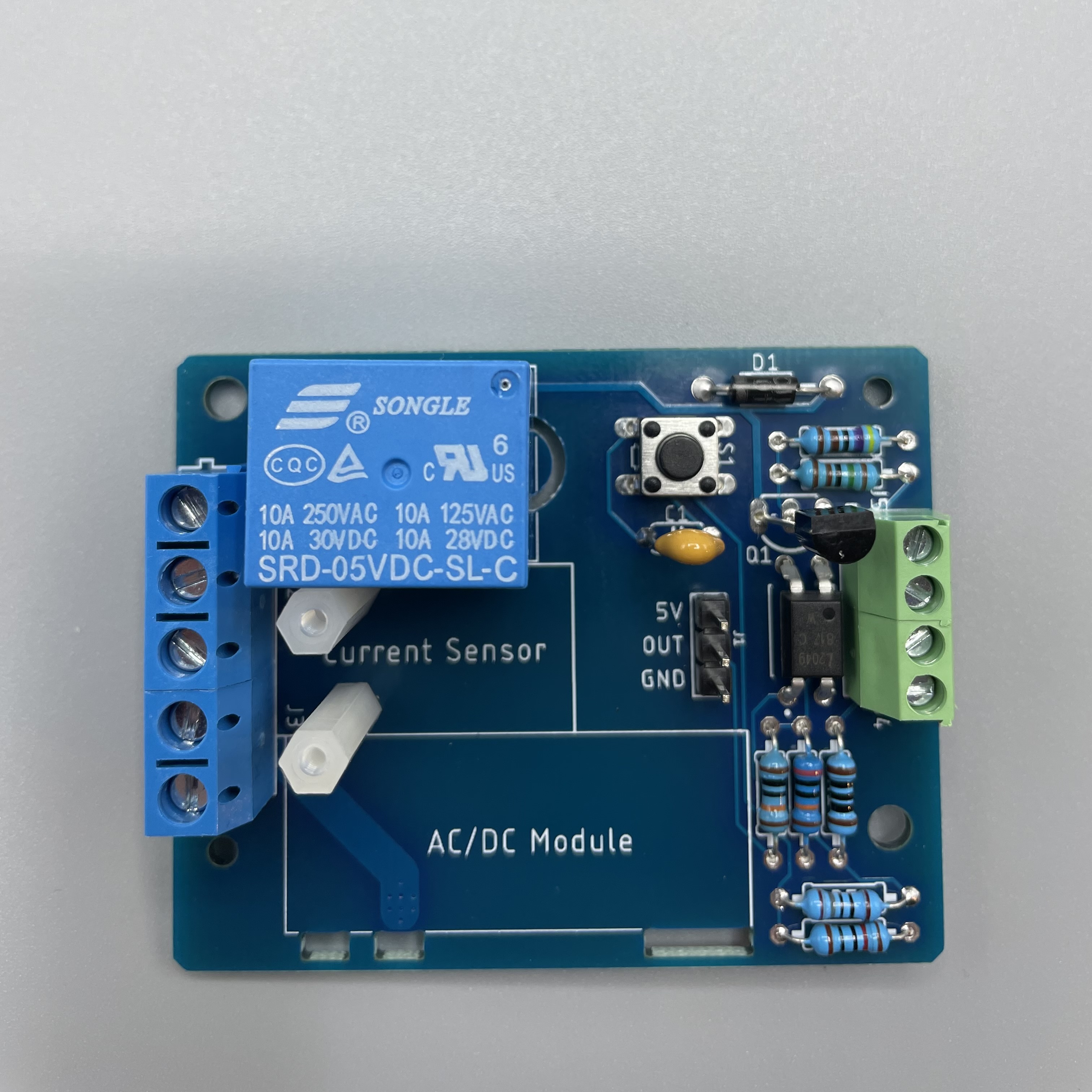
Get the relay and solder it on K1.
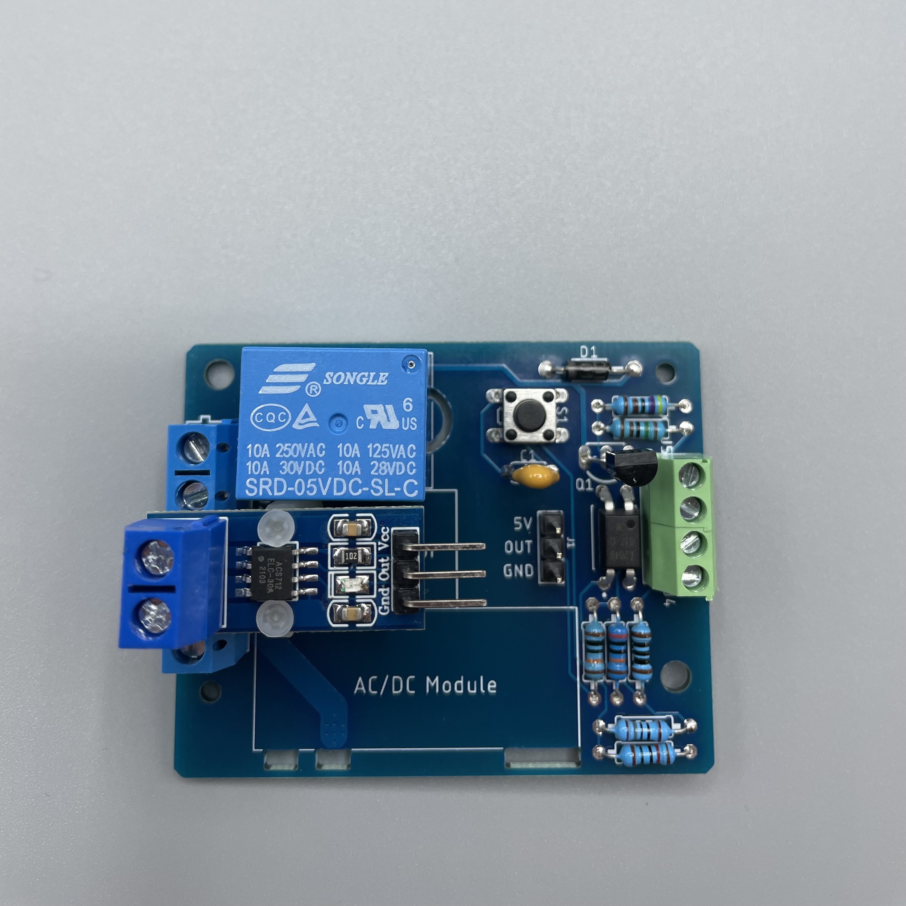
Use the M2 standoff plastic and the M2 screw plastic and screw them in at the current sensor.
Put the current sensor on top and screw it in with the last two plastic screws.
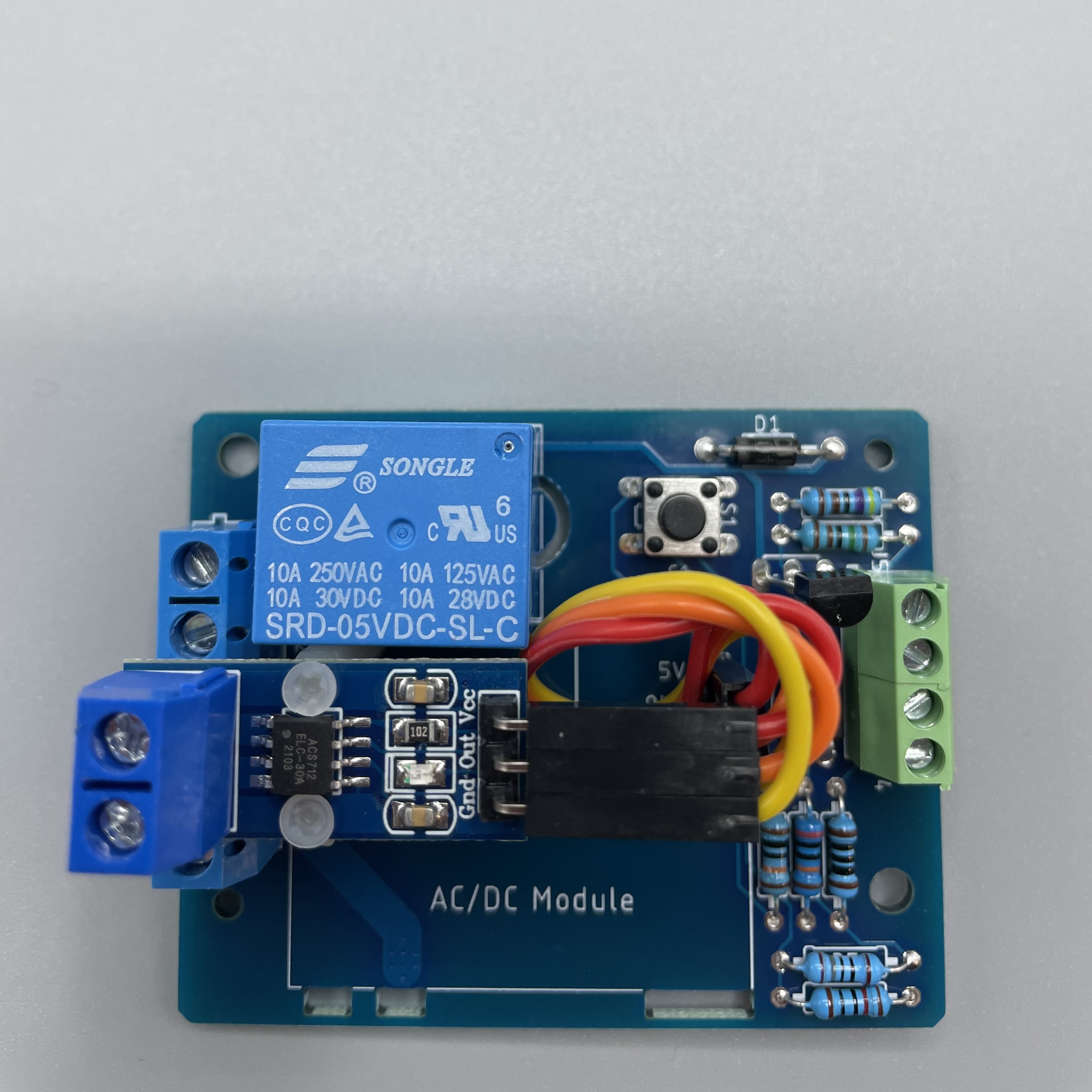
Now connect the pin header with the current sensor by using the three jumper wires. It should look like this.
Lastly solder the AC/DC Module.
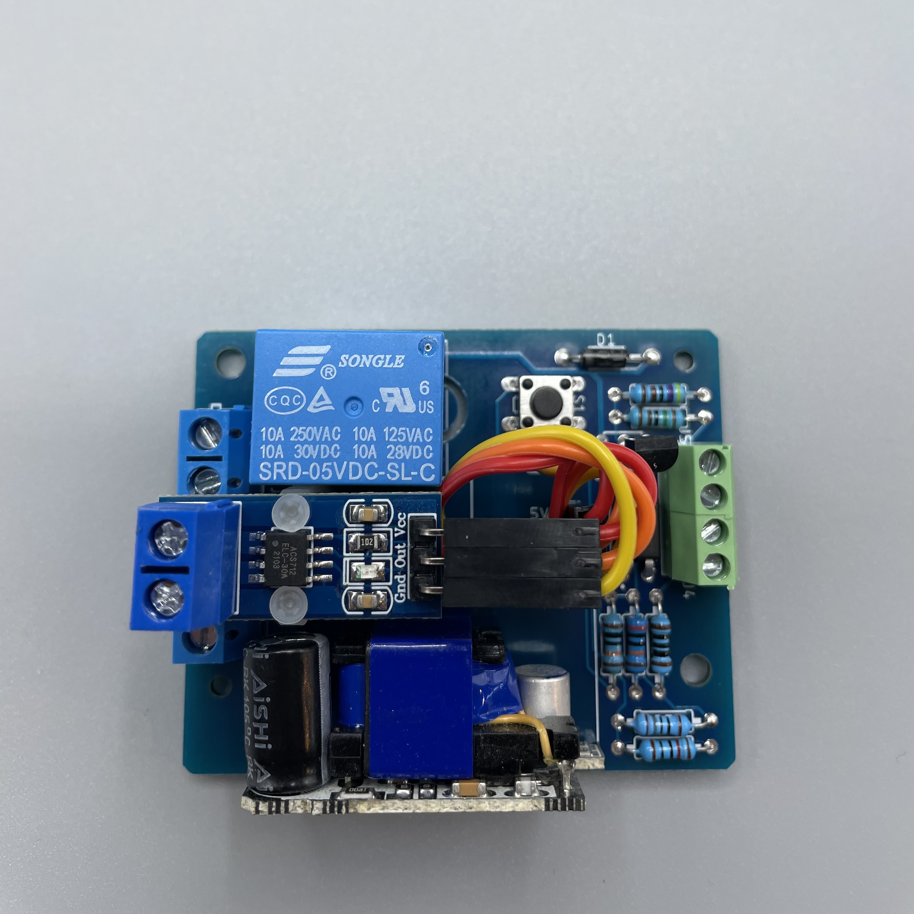
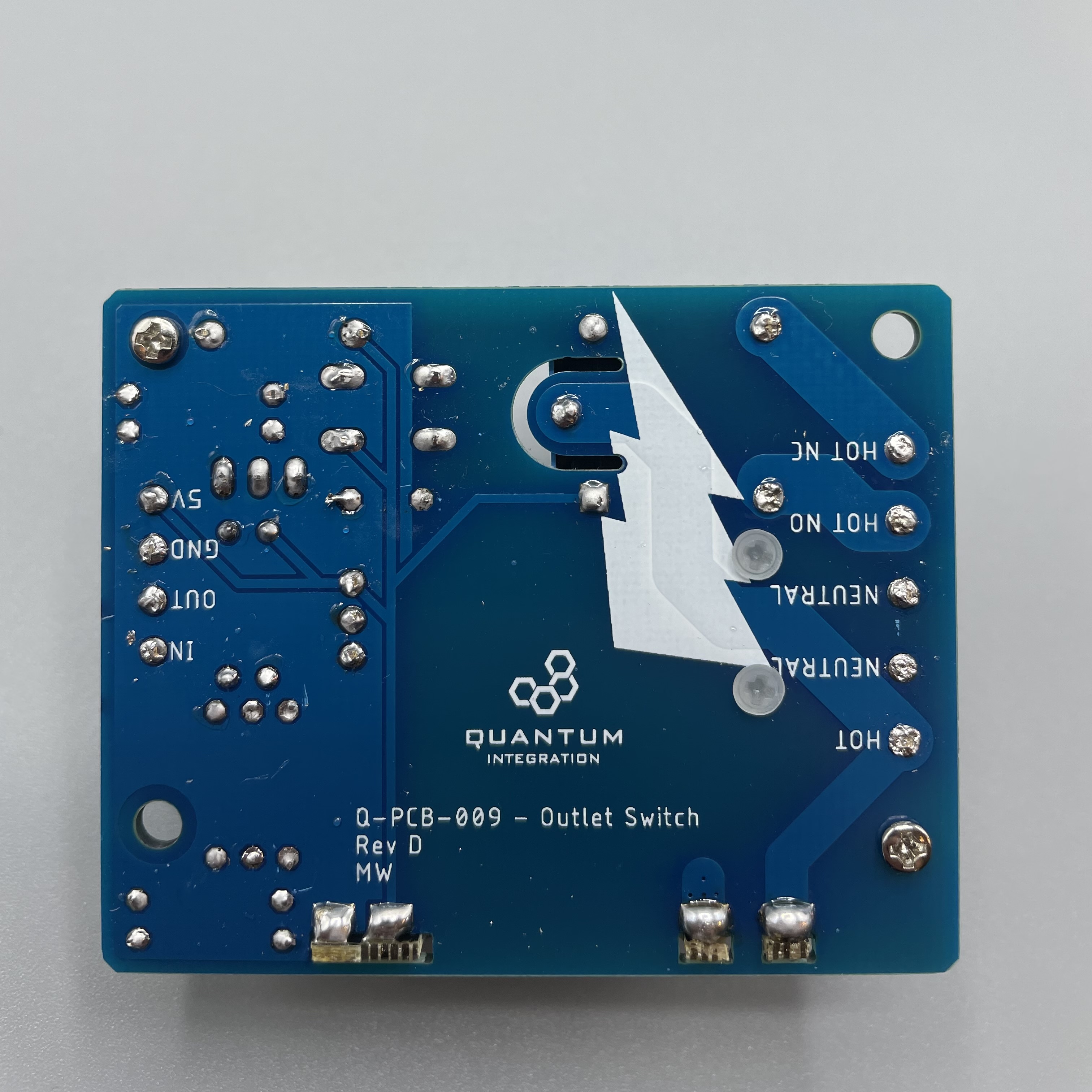
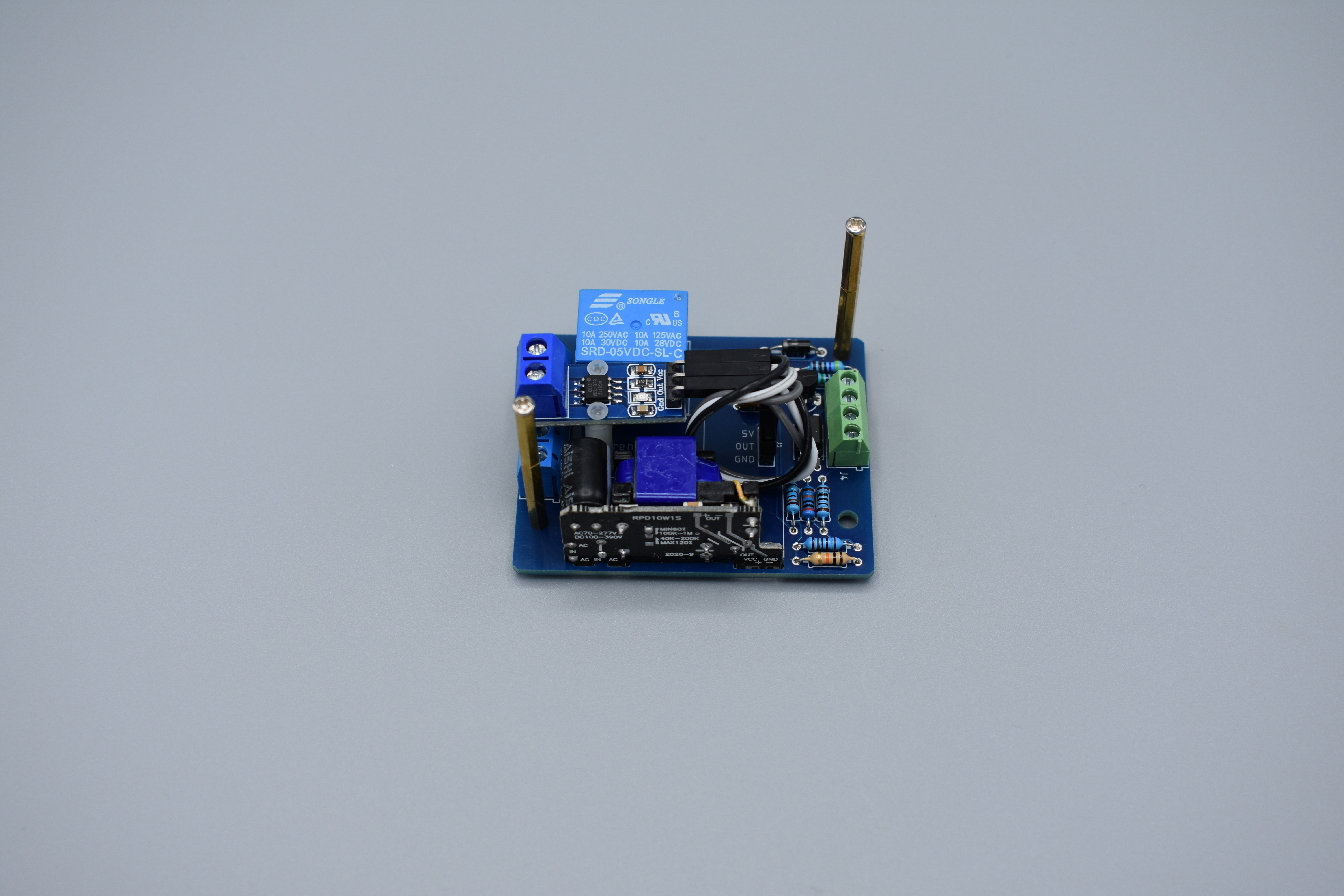
Your Outlet Switch DIY Kit is now ready to be used! The back should look like this.
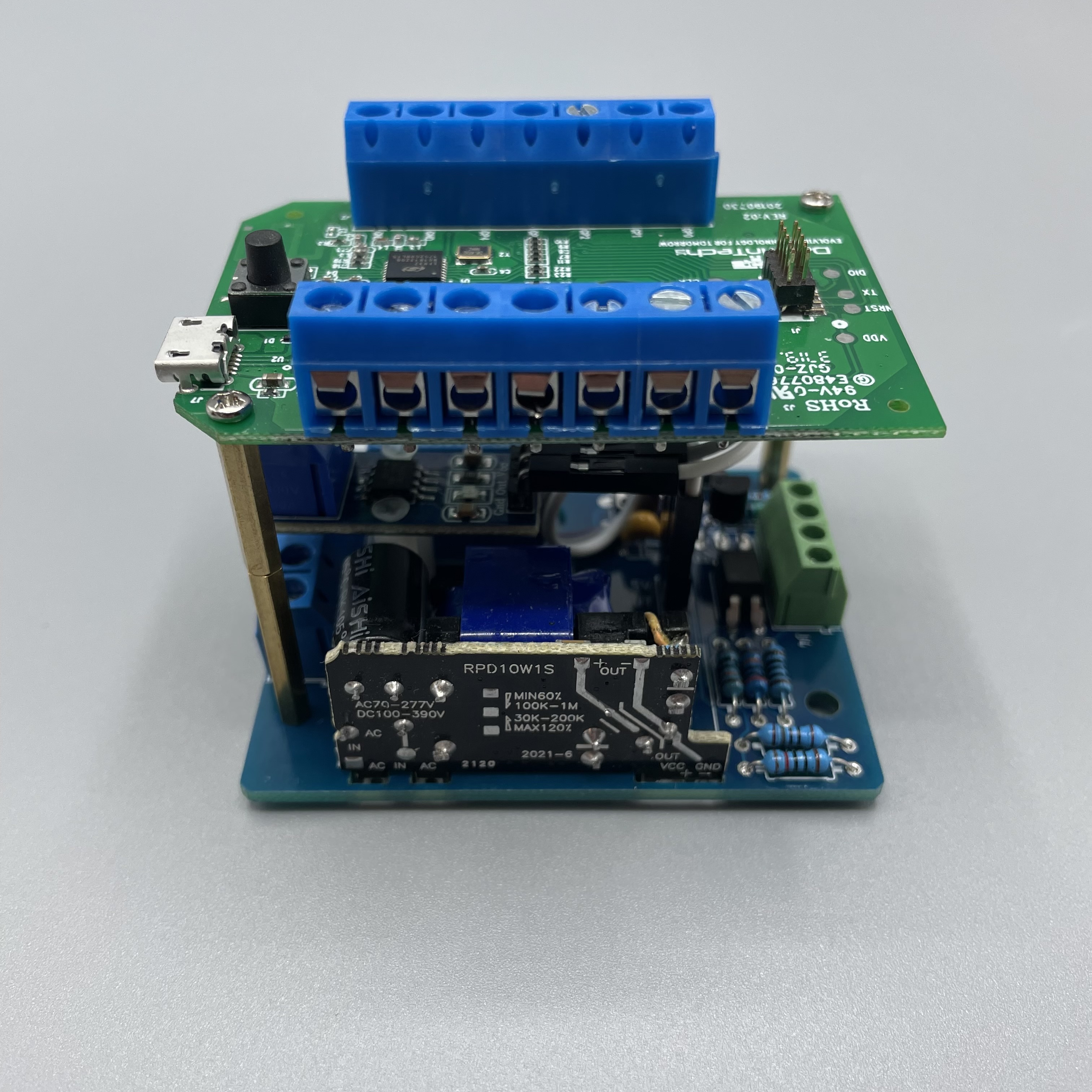
Using the metal standoffs you can screw a “stripped” Builder Base on top of the outlet switch.
Connecting to the Builder Base
Please refer to the following image on how to connect the DIY Kit to the Builder Base.

HOT NC: (NC = Normally closed) outputs HOT input, when relay is actuated
HOT NO: (NO = Normally open) outputs HOT input, when relay is not actuated
NEUTRAL: Passthrough of NEUTRAL Input
NEUTRAL: NEUTRAL Input (5V Power Supply)
HOT Input: AC/DC input
The Outlet Switch will allow you to switch any device that is connected to the outlet on and off like a lamp or a TV for instance. It can give you your energy usage data through the current sensor that sits on top of the DIY Kit. The Builder Base will be powered trough the Outlet Switch. The button on the Outlet Switch turns your project on and off or you can use your mobile app on your smartphone to do so.
Unfortunately the ACS712 current sensing board is not supported but will be shortly in the future.
Projects
The DIY Kit will control the power provided to a device like a fan or a heater. But any other device that can be turned on and off and uses a normal outlet can be controlled via the Outlet Switch DIY Kit.


It will also provide the current usage of the attached device by connecting it to the Quantum System.

The DIY Kit takes up to 240V AC and 30V DC at 10 A and uses a relay switch to power the outlet on and off. The Kit also includes a current sensor to provide current usage data of the attached device to the quantum system.
You will need a Romex or High AC voltage grade electrical wire and an extension cord for this type of project.
Assemble the DIY Kit and Extension cord
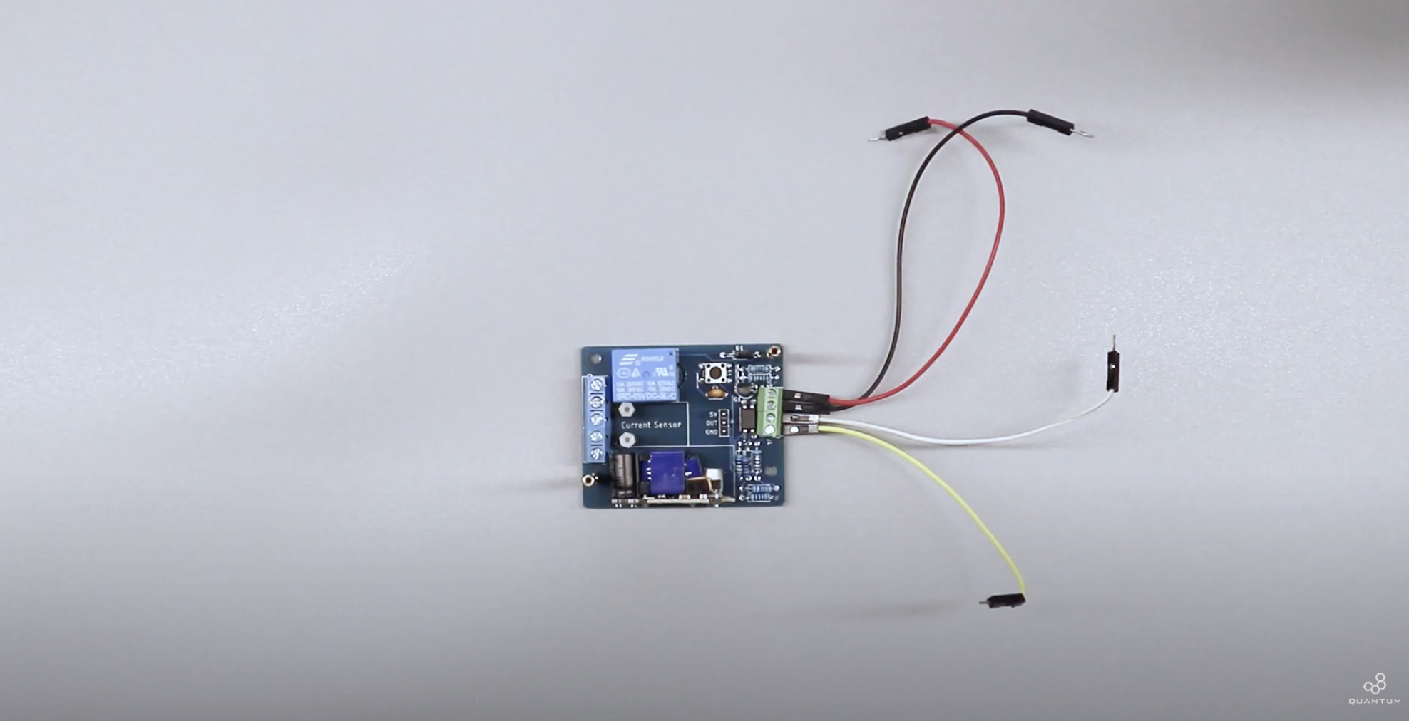
First assemble the DIY Kit. You can follow the step by step guide provided above or use the table with each designator. Once you finished that we gonna connect some male to male jumper wires to the DIY Kit. Use the reference under the DIY Kit to connect it to the right ports on your Builder Base later on. The END terminal is to control the relay switch (yellow). The OUT terminal is to receive data from the current sensor (white), GROUND terminal is to ground the Builder Base and 5V terminal is to power the Builder Base.
Instead of assembling the Kit directly into a wall outlet we will be connecting it to a standard extension cord. This provides easy mobility between projects.

Start by stripping of the main insulation of the extension cord.

Inside there will be three wires. A green, white and black one. The green is your ground, white is your neutral and black is your hot.

You will need to cut the white and black wires to connect to the DIY Kit. You can leave the green one untouched or make sure to reconnect it if you cut that one as well.

Now we strip the ends before connecting to the DIY Kit.

Since you will be connecting ac power we highly recommend using terminal connectors to on the end of each wire before connecting it to the kit. This will prevent the copper strands in the wire from fraying and possibly shorting the circuit and causing bigger problems.


Once the wires are ready to be connected on the bottom of the DIY Kit you will see the labels under the blue terminal block.

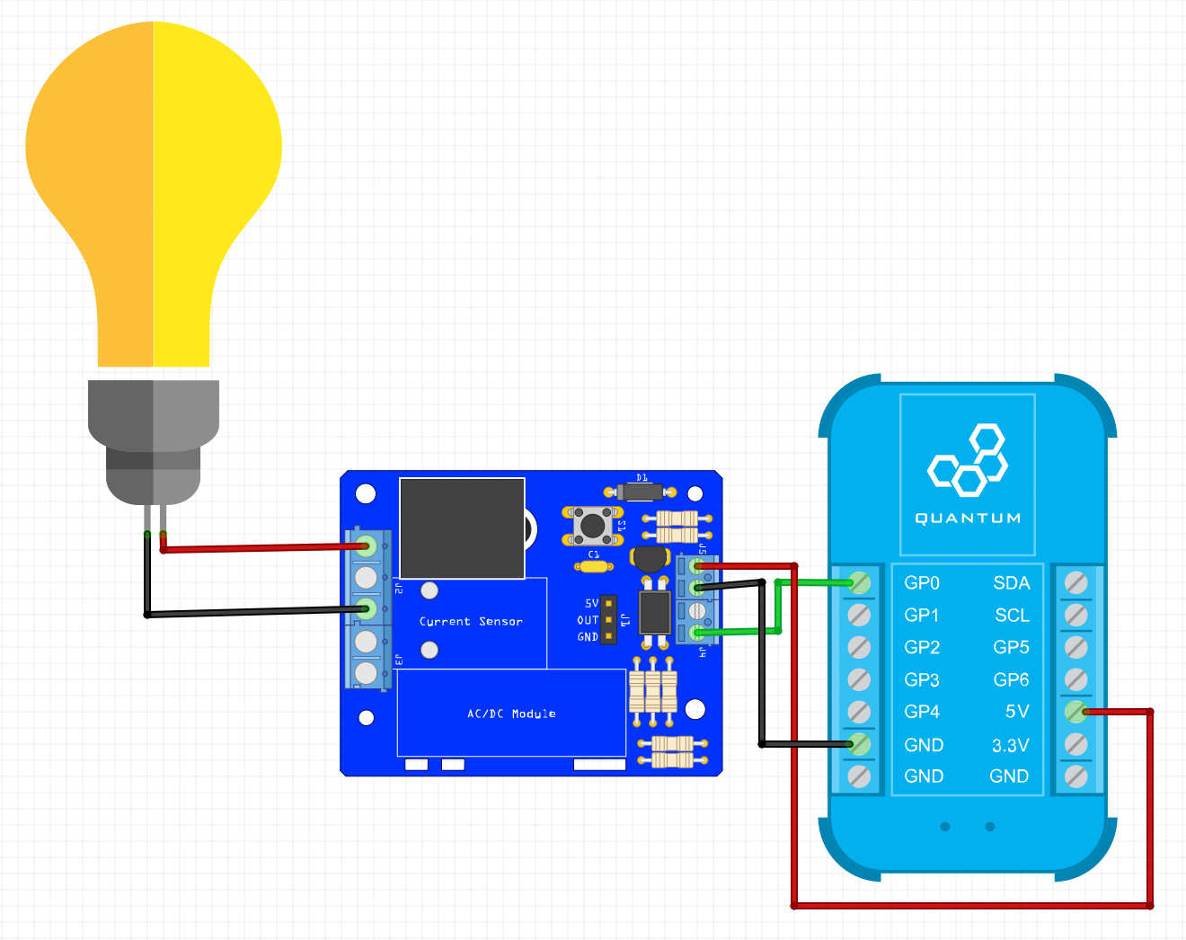
It will tell you which wires go where. You can also follow this schematic.

When you finished it should look like this.

Next connect the provided jumper wires from the pcb to the current sensor.

Connecting to a Builder Base
Lastly mount the Builder Base to the brass standoffs and connect those jumper wires we attached before. You can follow this schematic.

It should look like this.

You have now completed the assembly for the outlet switch DIY Kit. Go ahead and plug the extension cord into a wall outlet and you will see the Builder Base power on. Once that happens go to your Q-Server to complete the rest of the setup.
Pairing the Builder Base

Move to the Clients tab on your Q-Server.

You can see all paired Clients and also unpaired Clients. Go to the unpaired Clients tab.

Click on the three Actions dots to pair the Client with your Q-Server.

The Q-Server will start pairing the Client.

Once that is finished you can launch the Setup of the Client.

You can now edit the name as well ass the location where your Client is used.

Click “Save” when you finished.

The Client is now paired and setup.
Create the Firmware
The next step is to create the firmware we are using. Go to the firmware tab on your Q-Server.

Click the “+ Create New” to start a new Firmware.

Give it a name.

Once you finished click “Create”.

We now need to add hardware to our firmware file. Click on “+ Add Hardware” to start. Search for a Digital Out hardware. This will be used to control the power and switch it on and off. Once you found it, give it a name and add the hardware.

The second hardware we need is a current sensor. Search for Current.

You should see both added hardwares on the right side.

We now need to edit those two hardwares. Click on the arrow.

For the driver we select “GPIO”. Pin is in our case “GP0”. If you followed our instructions it is the same for you. Mode set to “Initially Low”. Click save.

For the current sensor set the driver to “ACS712”. Pin is “GP1”. Resolution is set to 10ma and the ACS Model ist 30A.
The last step is to upload the firmware. Click the three dots and then hit “Upload”.

Select the right Client.

Hit “Upload”. Let’s proceed to the next step building the app.
Create the App
While the firmware is uploading we will create a very simple app to control the heater. Move to the Apps tab on your Q-Server.

Hit “Create New”. We name the app “Heater Outlet Switch”.

You will find yourself on the canvas. The following picture will show you how the app should look like.

We need one current hardware object, one digital out hardware object like we used in our firmware. Then we need a switch interface object and a text interface object. Those objects will make sure that we can visually see the current usage and also turn the heater on and off via the dashboard. Don’t forget to name the objects to differentiate them later on. Once you finished hit “Save App”.
Back on your Apps tab you see a stopped app.

Click on the play button to start the mapping.

Now you can see the the two hardware objects we added and we now need to connect them to the firmware we created before. Click on the “Current Sensor” and select the corresponding hardware. Select it and click done.

For the Switch we will do the same.

Click “Save + Run”.
The Play button should turn green now.

The app is running and we should have a look at it in the dashboard. Click on the dashboard icon in the top right corner.

Select the Heater Outlet Switch app.

As you can see the heater is turned off and currently 363 mA are used. If we turn on the heater, the current usage will change.

This is a simple app to use the DIY Kit. In the next step we will show you an more advanced app for this project.
Create an advanced app
We are going to take this one step further and create a true automated project. You can control the device on and off, read current usages and change temperature of the heater. To do so we need to change the app we created before.

We are pulling the data from the Current Sensor hardware object. This will be displayed on a time graph using a series of historic data time stamp and time graph objects. We can see the current usage over a period of time with the heater connected to the Outlet Switch DIY Kit. Additionally we are also able to control the switch of the DIY Kit using the on and off switch interface object we used before. To take it a step further we included a couple more code objects and interface objects to also set a temperature for the heater. We have a set temperature input number interface object where we can set a temperature we want it to ideally be. Then we have a variable temperature input number. Typically you would have a temperature hardware object for a DHT11 temperature sensor. Since the data is coming in pretty low we will show you this with two set temperature to give you an idea how it will look like. Both numbers will be compared and depending wether the room temperature is greater or lower than the set temperature the heater will be turned on or off.
We gonna start the app and move back to the dashboard.

You can see the time graph on the right and all controls on the left. We can turn the heater on and off, clear all data, set the temperature for the heater. Turning on the heater will let the current usage rise.

If we turn it off, the current usage should fall. If we set a temperature now and say a sensor reads 60 fahrenheit and we want 70, the heater should automatically be turned on.

Same the other way around. If the temperature of the sensor ist higher than the set temperature, the heater will stay off. To clear the graph and all other data hit the “Clear All” button.
Conclusion
That is how you can use the Outlet Switch DIY Kit with the Quantum System to create either a simple program or and automated program to control appliances that are connected to it.
Happy making!
Gallery
Resources
App & Firmware
|
|
This DIY Kit page is currently optimized for revision D.
Current revision
Assembly files for the current revision of the DIY Kit (Rev D): | https://github.com/QuantumIntegration/Q-PCB-009-Outlet-Switch-Hardware-Files |
|---|
Older revisions
- | - |
|---|