| Table of Contents |
|---|
Overview
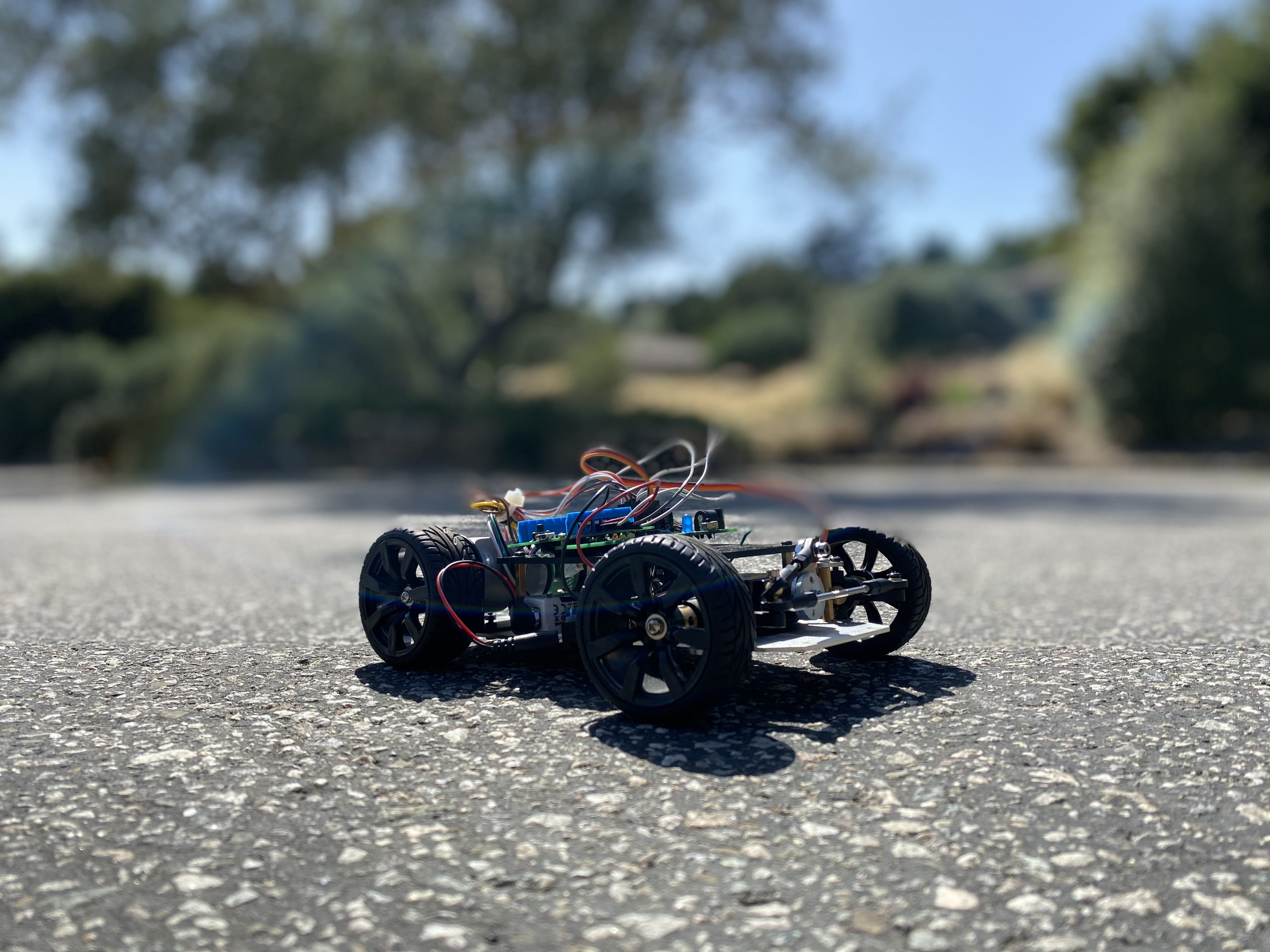
The Steering Car PCB kit is a fun and rewarding build that will familiarize you with H-bridge motor control and Servos.
The car behaves like any other RC car, it makes agile turns and zips around at speeds much greater than that of our Mecanum Kit build. The PCB also has a voltage regulator built into it, giving you the option to power your project with a 9V battery.
You can purchase the car chassis that we used (linked below), find another similar chassis (one that uses two brushed DC motors and a servo), or you can create your own chassis from scratch!
|
|
|
|
Things used in this project
Hardware components
Picture | Name | Quantity | Price(As of 7/10/20) | Link |
|---|---|---|---|---|
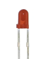 | Radial LED (5mm) | 1 | $.05/LED (when purchased in a 100 pack) | Included in Starter Kit Or you can purchase it here |
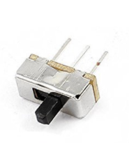 | Sliding Switch | 1 | ~$.26/Switch | Can be purchased here |
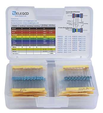 | 220Ω Resistor | 1 | $.02/Resistor | Included in Starter Kit Or you can purchase it here |
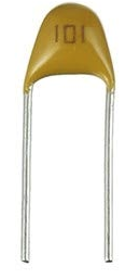 | 100nf Capacitor | 2 | ~$.03/Capacitor | Can be purchased here |
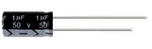
| 100uf Polarized Capacitor | 1 | ~$.03/Capacitor | Can be purchased here |
| 10uf Polarized Capacitor | 1 | ~$.03/Capacitor | Can be purchased here |
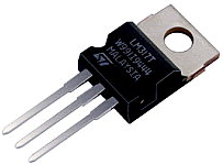
| 7805T | 1 | ~$.64/Regulator | Can be purchased here |
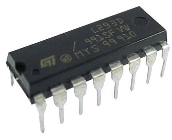 | L293D | 1 | ~$3.91 | Included in Starter Kit Or you can purchase here |
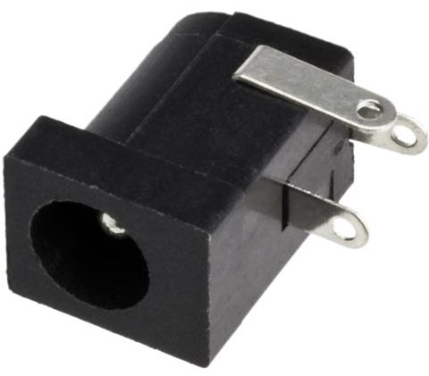
| 2.1mm Barrel Jack | 1 | $.60 | Can be purchased here |
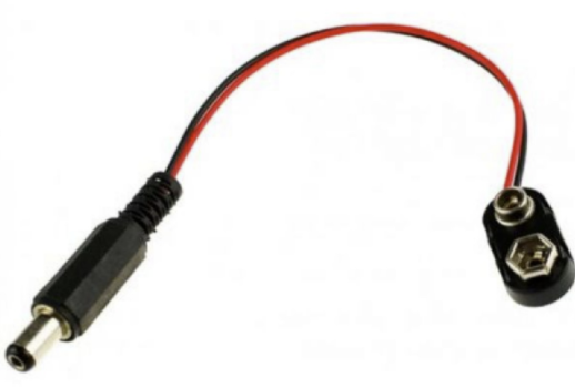
| 2.1mm Barrel Jack to 9V adapter | 1 | ~$1.2/Adapter | Can be purchased here |
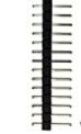 | 1x3 pin header | 1 | ~.2/Header | Can be purchased here |
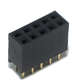 | 2x5 Pin Header | 1 | ~$.67/Header | Can be purchased here |
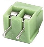 | 1x2 3.5mm Terminal Block | 2 | ~.22/ Terminal Block | Can be purchased here |
 | Steering Car PCB | 1 | $2-5 | - |
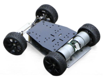 | Car Chassis, Servo, and Motors. (Any kit that uses 2 brushed DC motors and a servo can be used for this build. ) | 1 | ~$69.90 | Can be purchased here |
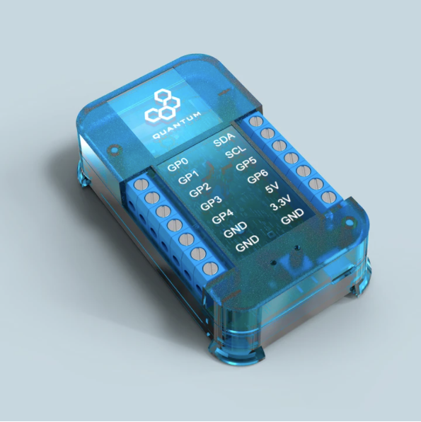 | Q-Client Builder Base | 1 | $49 |
Tools Used
Picture | Name | Quantity | Link |
|---|---|---|---|
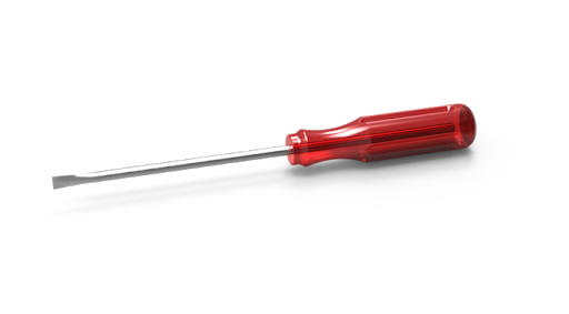 | Small slotted-head screwdriver | 1 | Included in Starter Kit or you can pick from one on our Recommended Tools List |
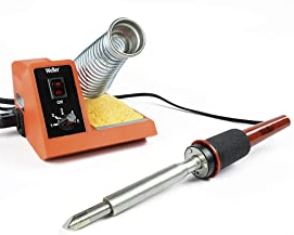 | Soldering Iron | 1 | You can pick from one on our Recommended Tools List |
 | Solder | 1 | You can pick from one on our Recommended Tools List |
 | Diagonal Cutters | 1 | You can pick from one on our Recommended Tools List |
 | Work Holder | You can pick from one on our Recommended Tools List |
Story
The Idea
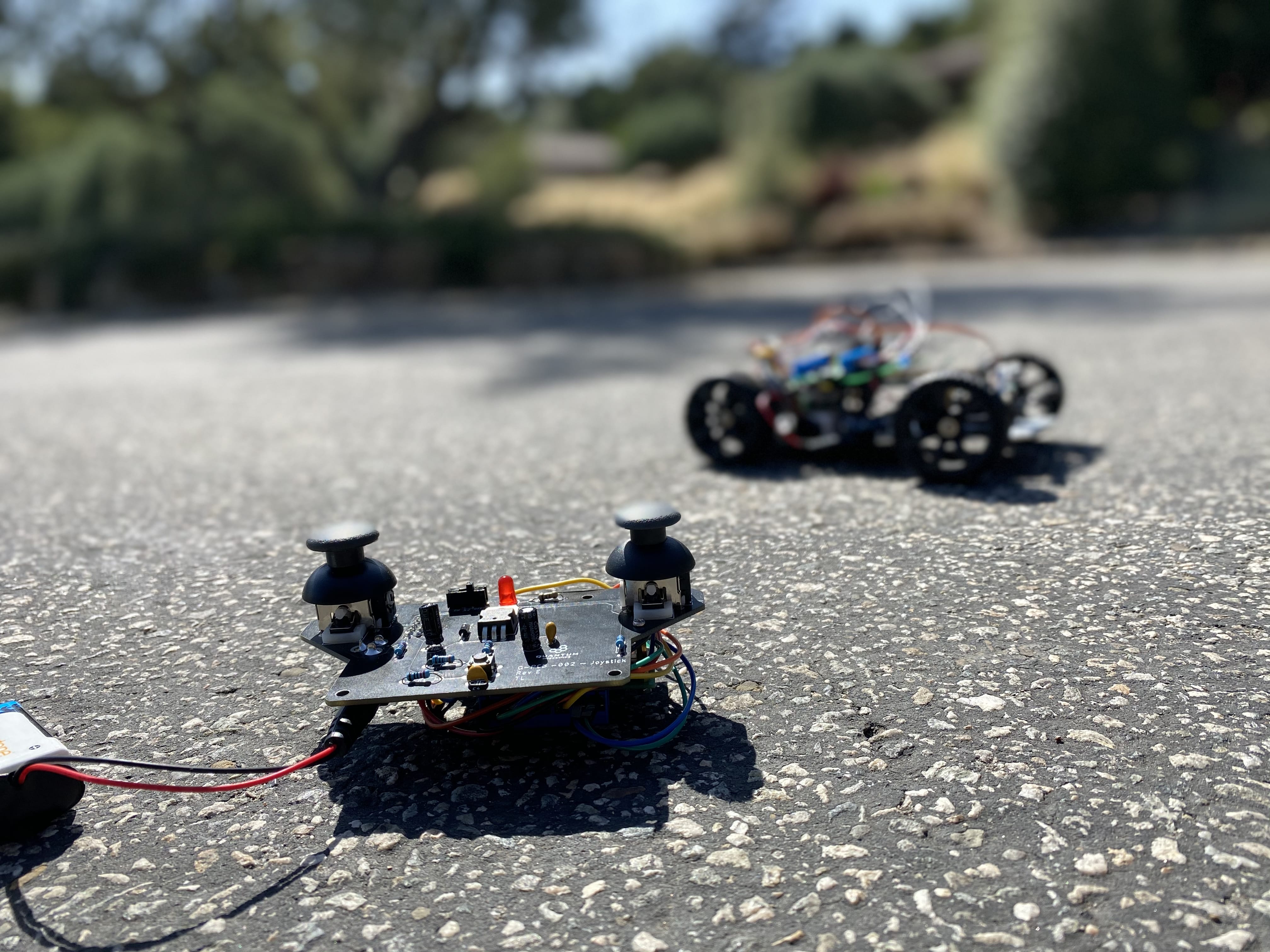
To make a fast, agile, and easy to use RC car with the Quantum platform.
Video
| Widget Connector | ||||||||||
|---|---|---|---|---|---|---|---|---|---|---|
|
Build Process
Step 1: PCB Assembly and Soldering
Download the Steering Car DIY Kit Bill of Materials:
| View file | ||
|---|---|---|
|
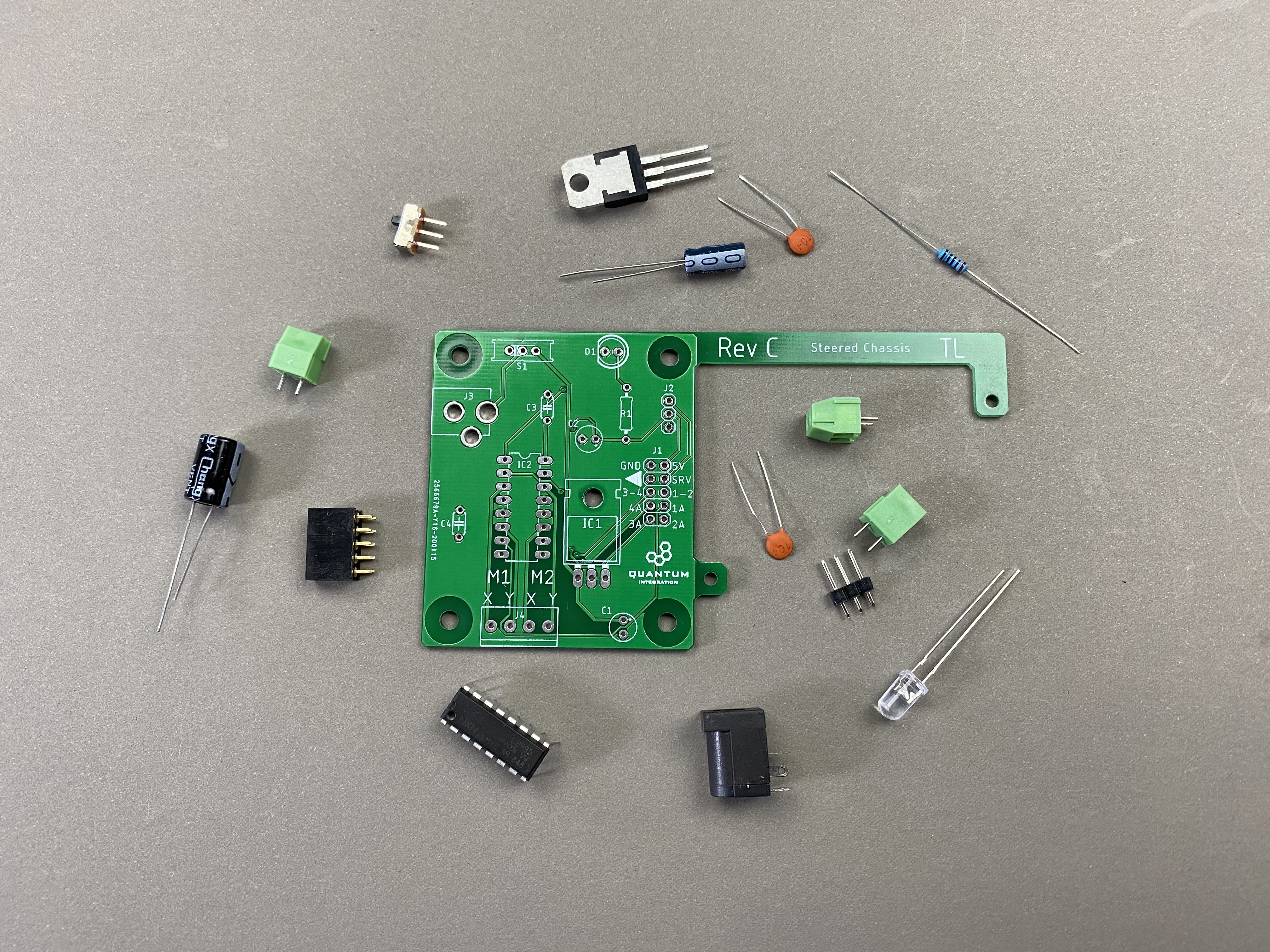
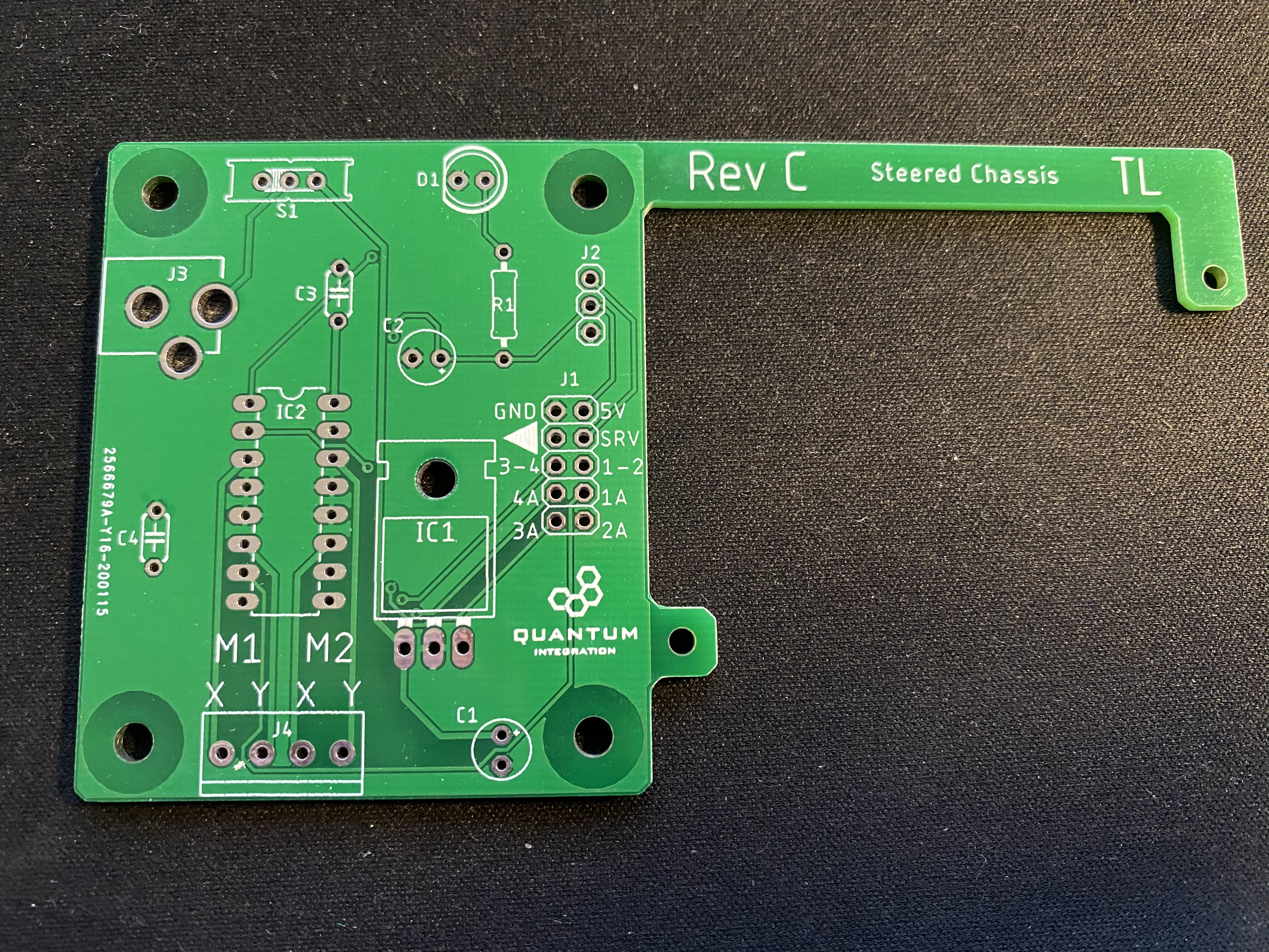
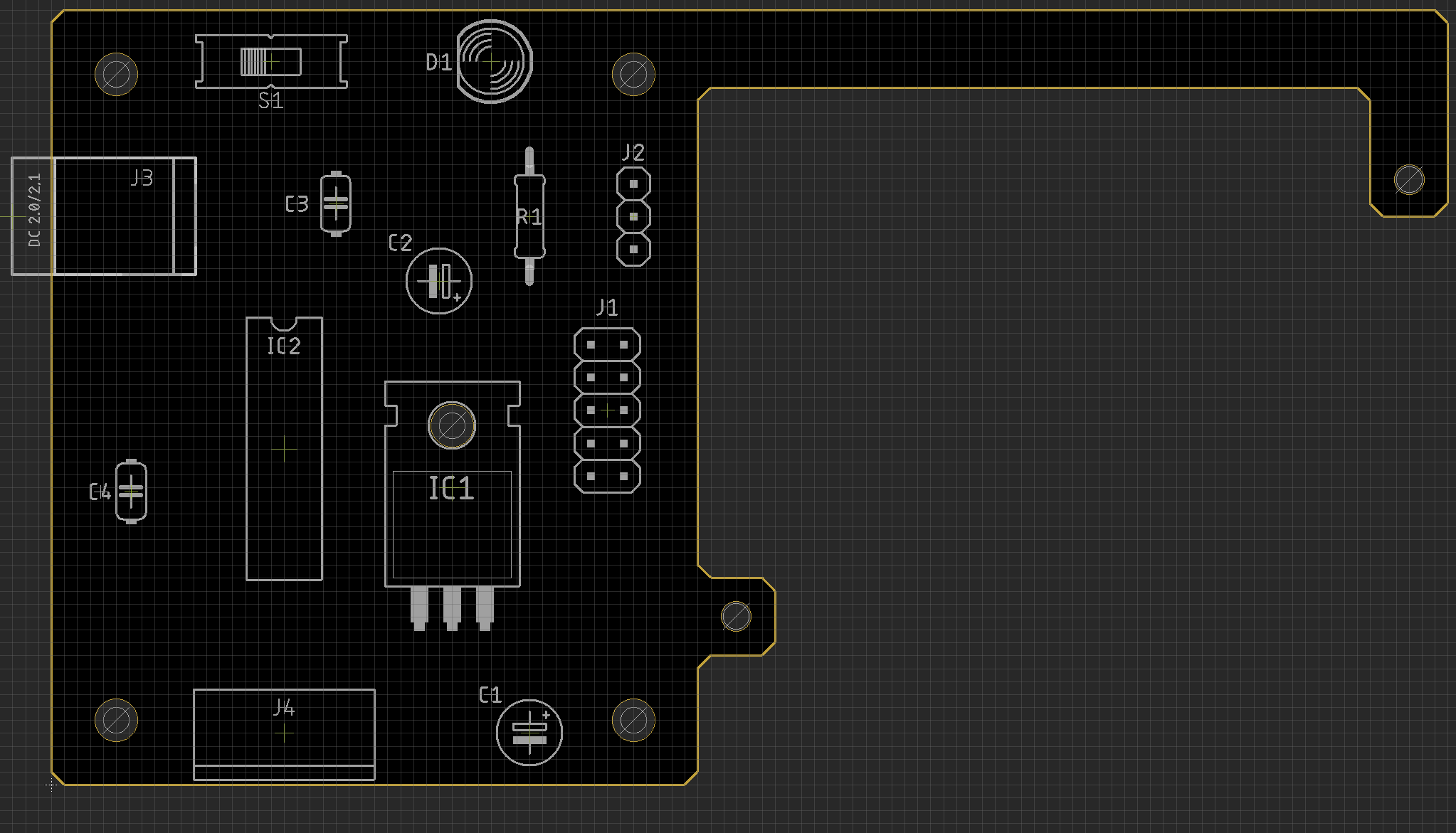
Gather your Steering Car Kit PCB and all required components listed in the BOM.
It is especially important to follow the BOM exactingly as it tells you where to place the components on the PCB. The fifth column on the BOM is the “parts” column. This column designates which position on the PCB you are to pace the component. For example, if under the parts column you have a resistor labeled r1 you would then find the position marked r1 on the PCB and place the resistor there.
Using some form of work holder is advised. You can find a list of suitable work holders on our Recommended Tools List.
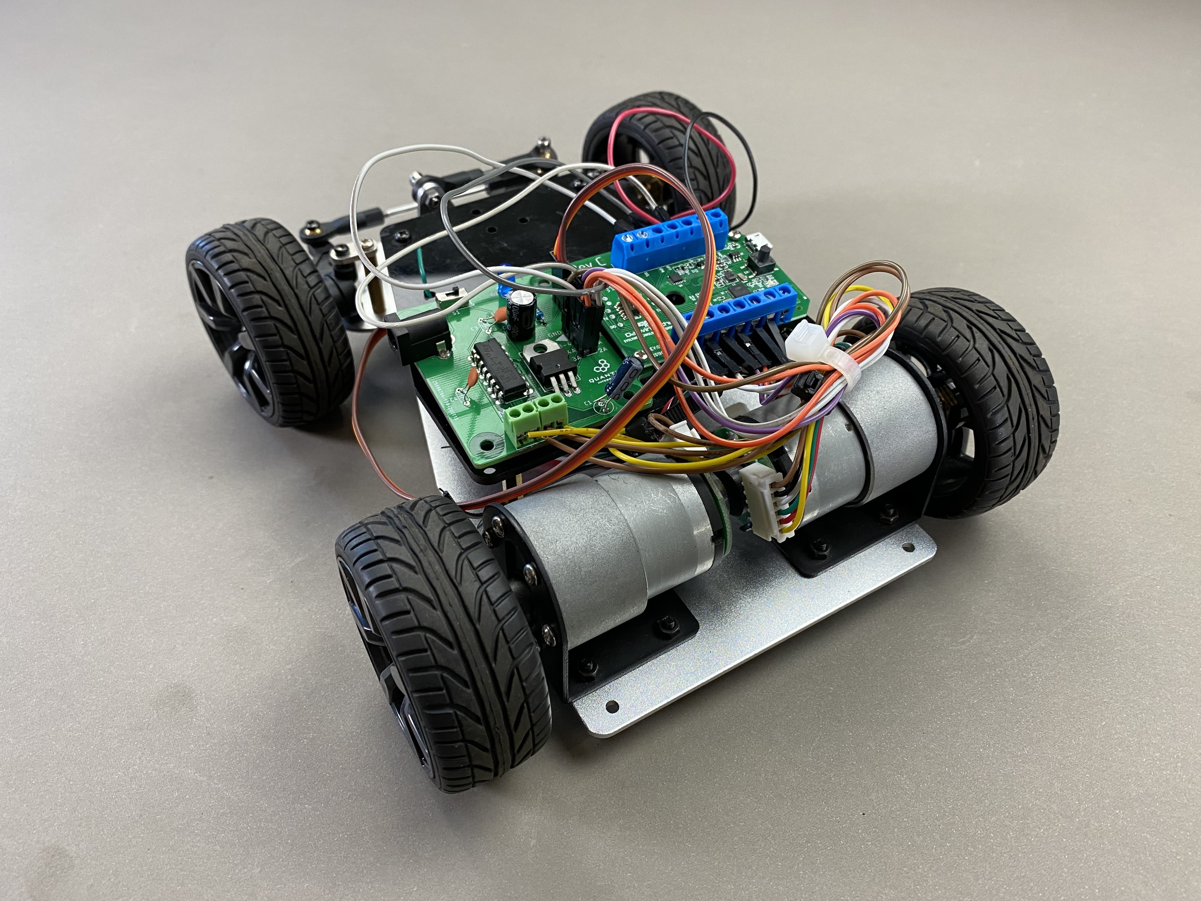
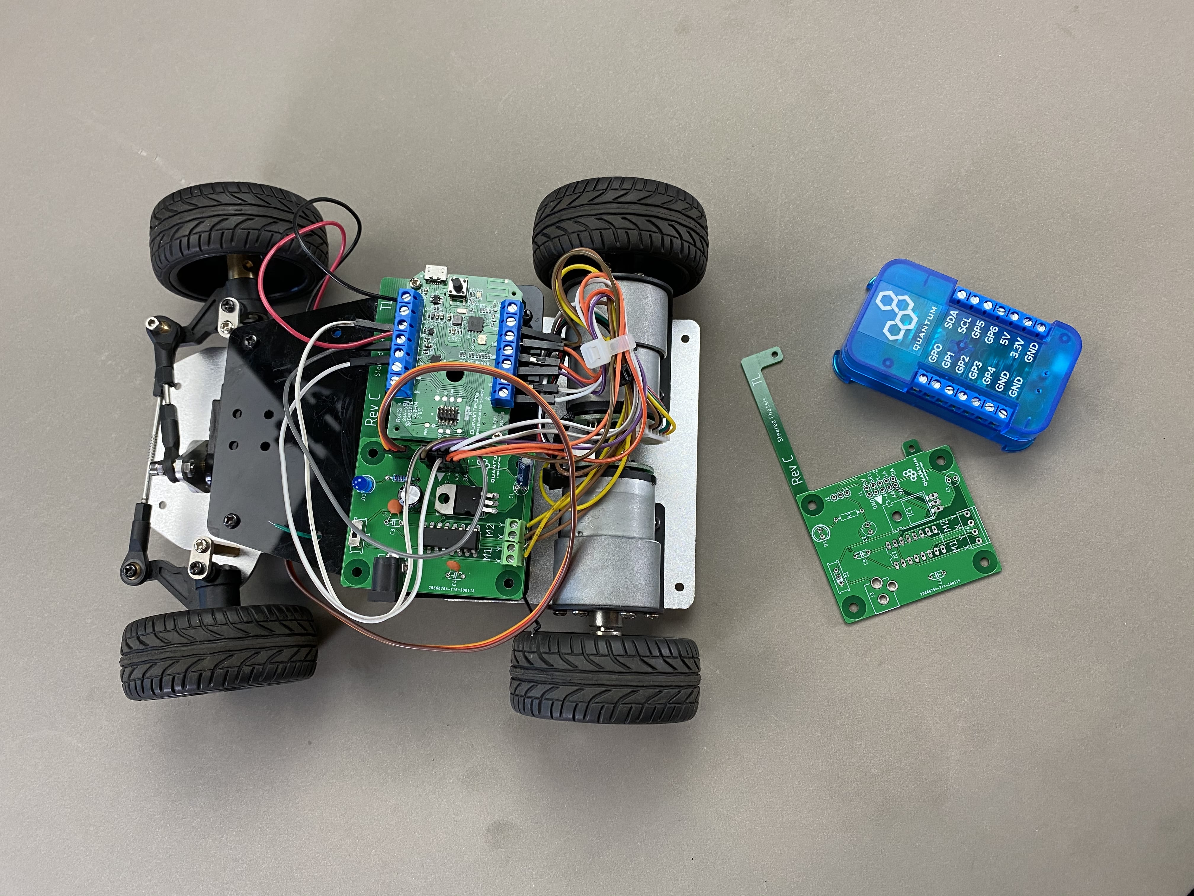
Step 2: Connecting the Motors and Servo to the board
Here you can see the junctions labeled M1 and M2. These are the terminals in which you will connect your motor leads.
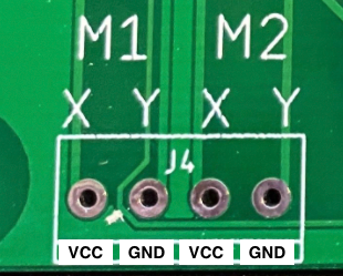
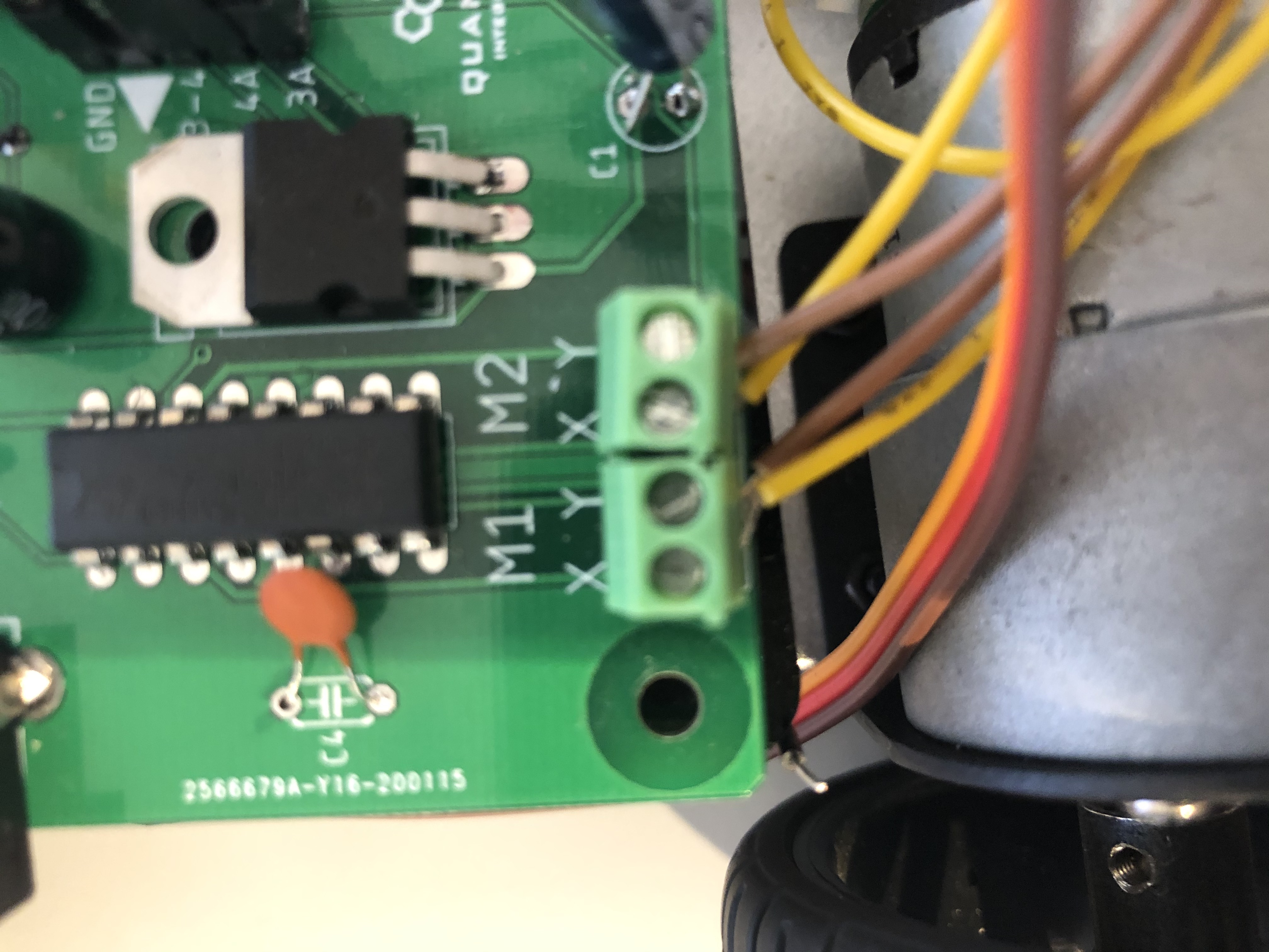
Connect the positive and negative leads from your motors as follows.
X | Y | |
|---|---|---|
M1 | VCC | GND |
M2 | VCC | GND |
Take care to ensure that your motors are wired correctly. Otherwise, the two motors will spin in opposite directions.
Now, wire your servo to the PCB as follows.
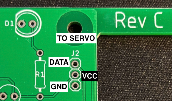
PCB | Servo |
|---|---|
Top | Data |
Middle | VCC |
Bottom | GND |
This will complete the hardware wiring on your PCB!
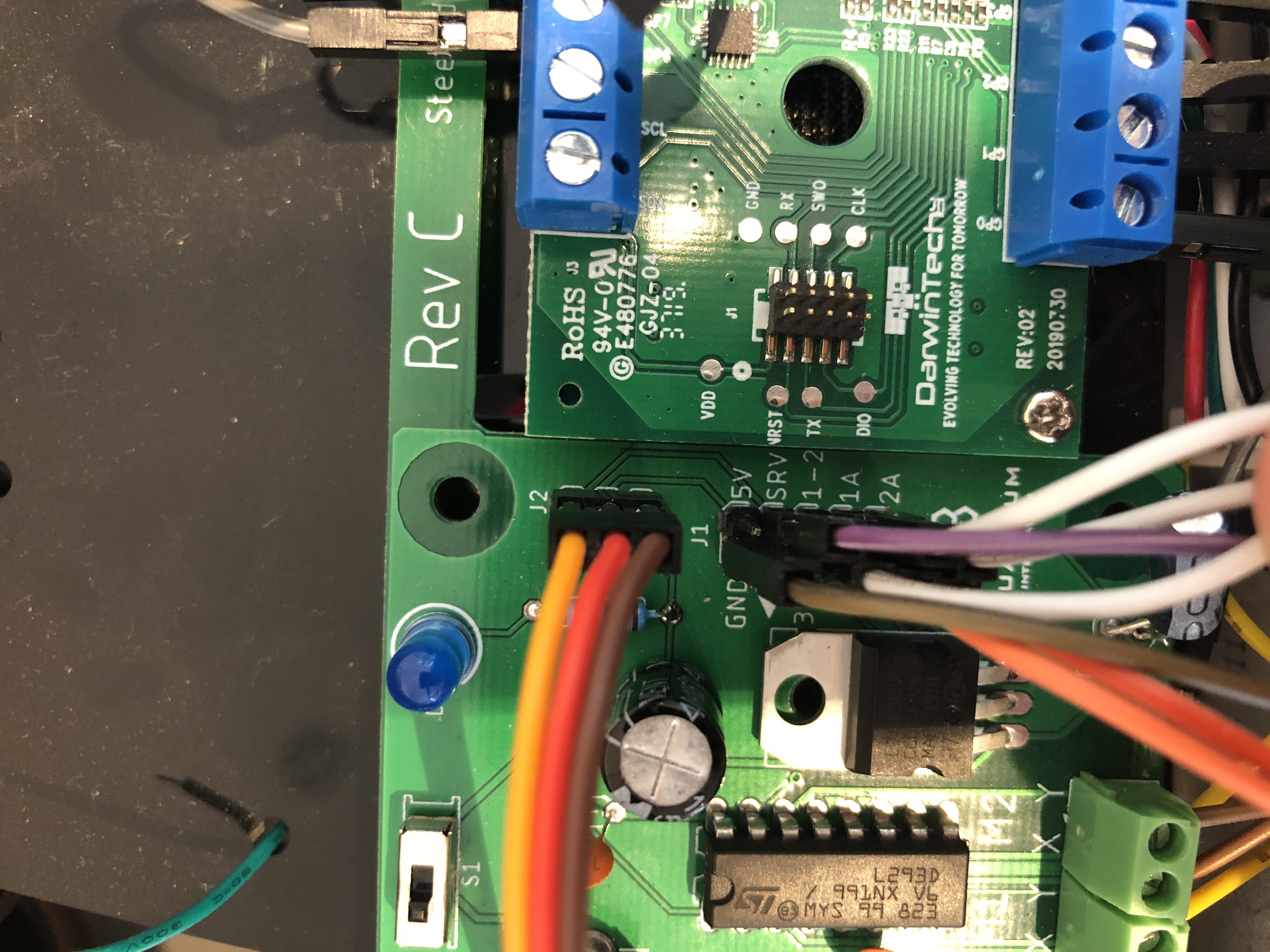
Step 3: Wiring your Chassis to the Builder Base
Once all your motors are wired and mounted, you can connect your PCB to the Builder Base. You can follow along to the diagram and table below to ensure you have the appropriate wiring.
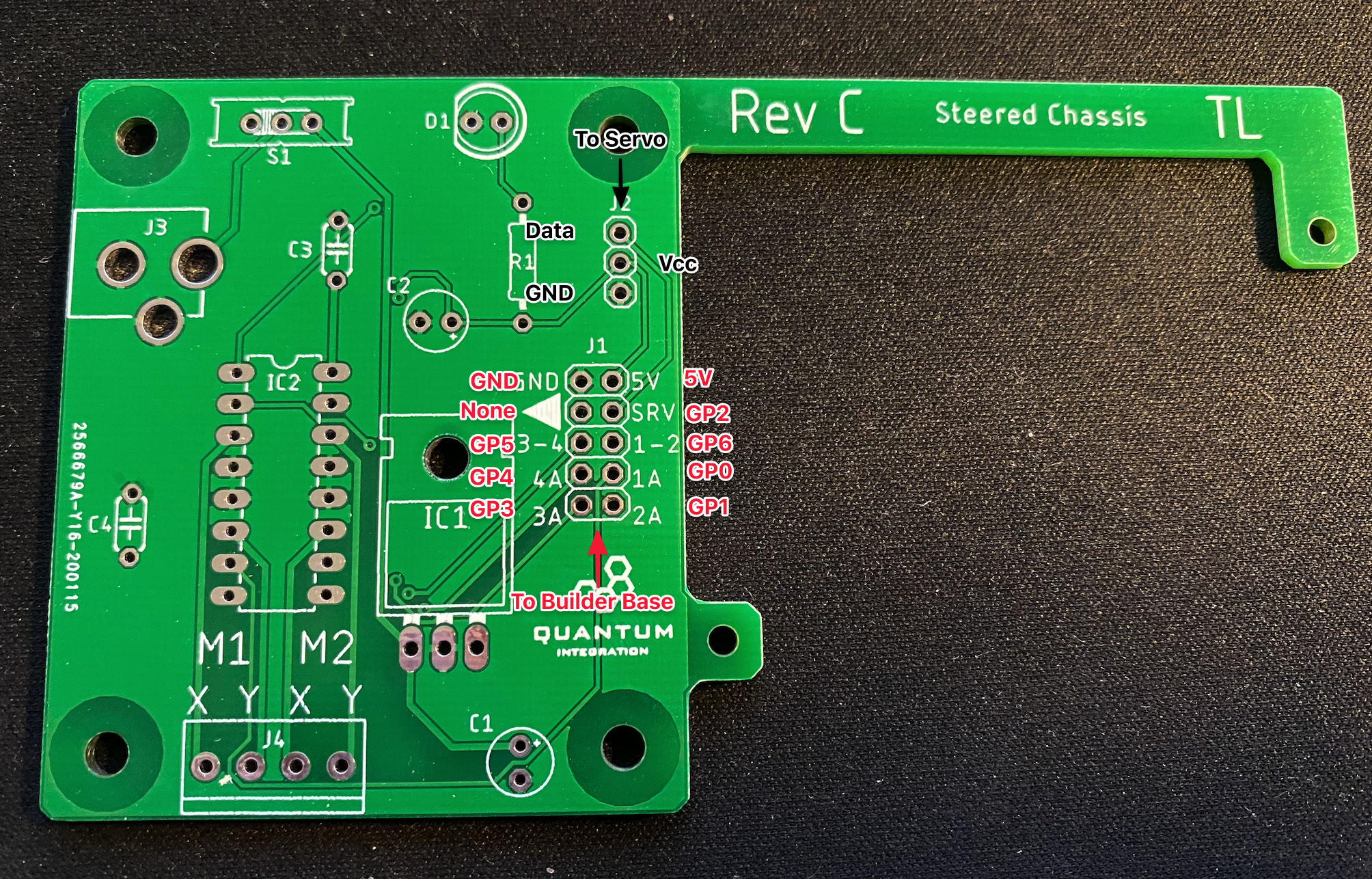
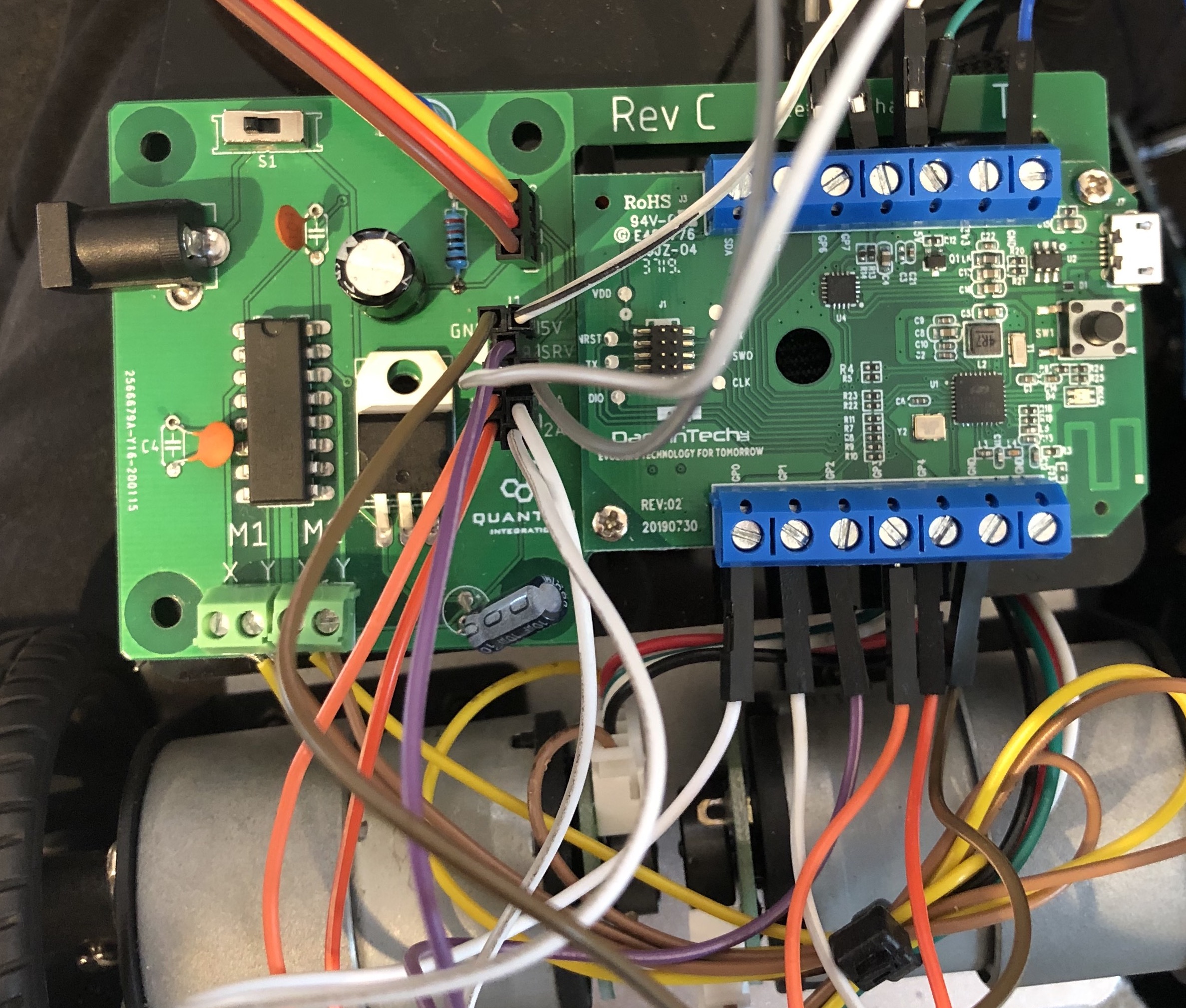
Steering Car PCB | Builder Base |
|---|---|
GND | GND |
5V | 5V |
SRV | GP2 |
3-4 | GP5 |
1-2 | GP6 |
4A | GP4 |
1A | GP0 |
3A | GP3 |
2A | GP1 |
| Note |
|---|
Be careful to make sure that you connect the PCB to 5V and not 3.3V |
Step 4: Build the Firmware
| Tip |
|---|
Remember: All Apps and Firmware Files are available in the resources section at the bottom of the page! |
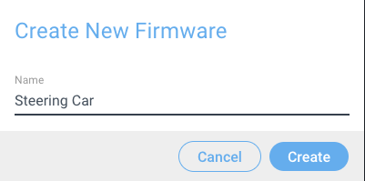
Navigate to the Firmware Builder and create a new Firmware file. We named ours Mecanum KitSteering Car.
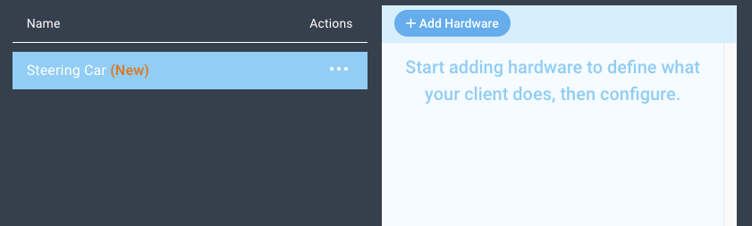
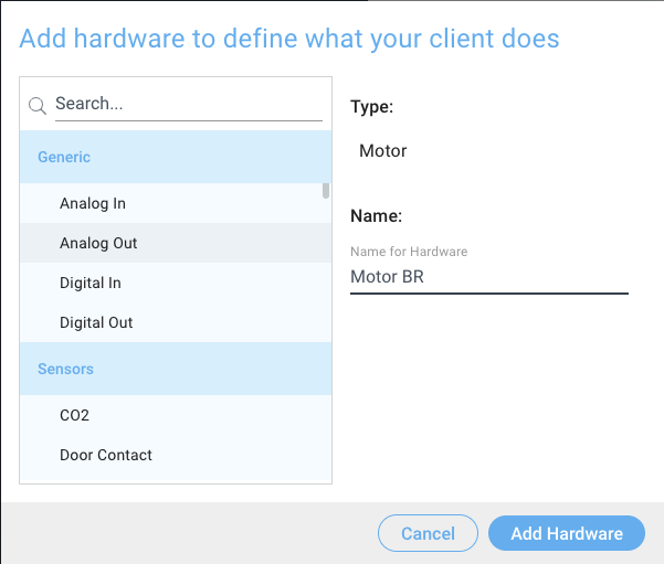
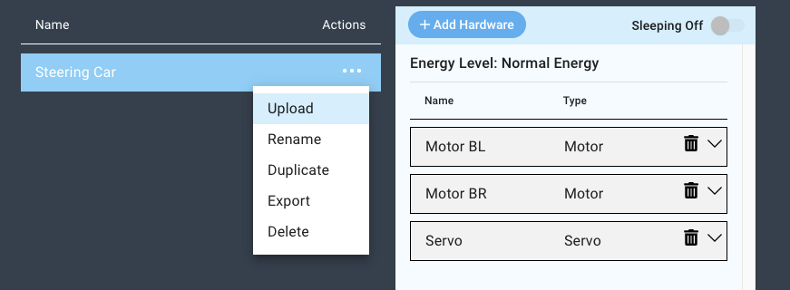
Next, click the “+ Add Hardware” button and find the Motor device via the search bar, select it, name it, and then click “Add Hardware”. We named ours Motor BL.
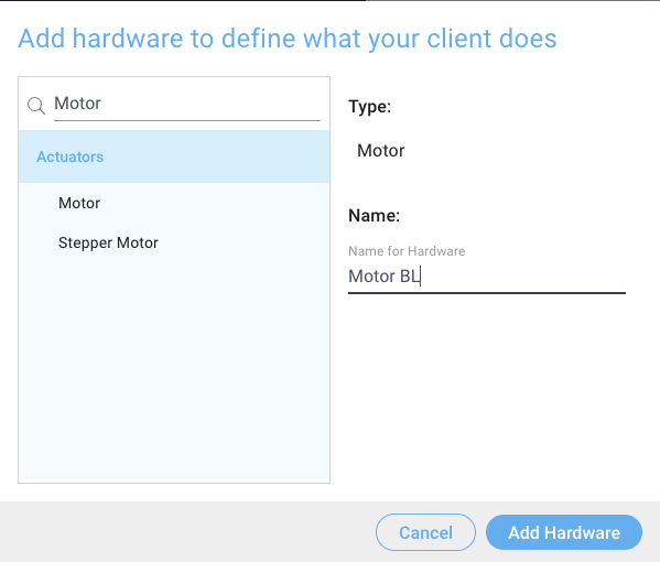
Repeat these steps again, but this time name the motor Motor BR.
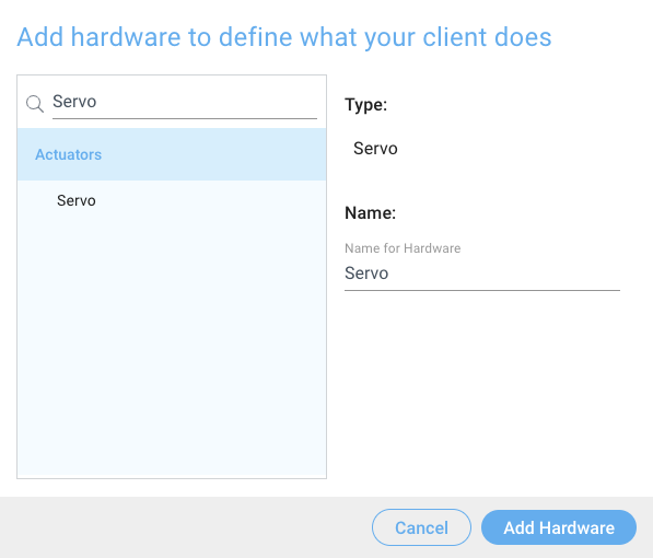
Next, add a servo. We named ours Servo.
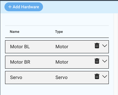
You should now have two motors and a servo in your devices list.
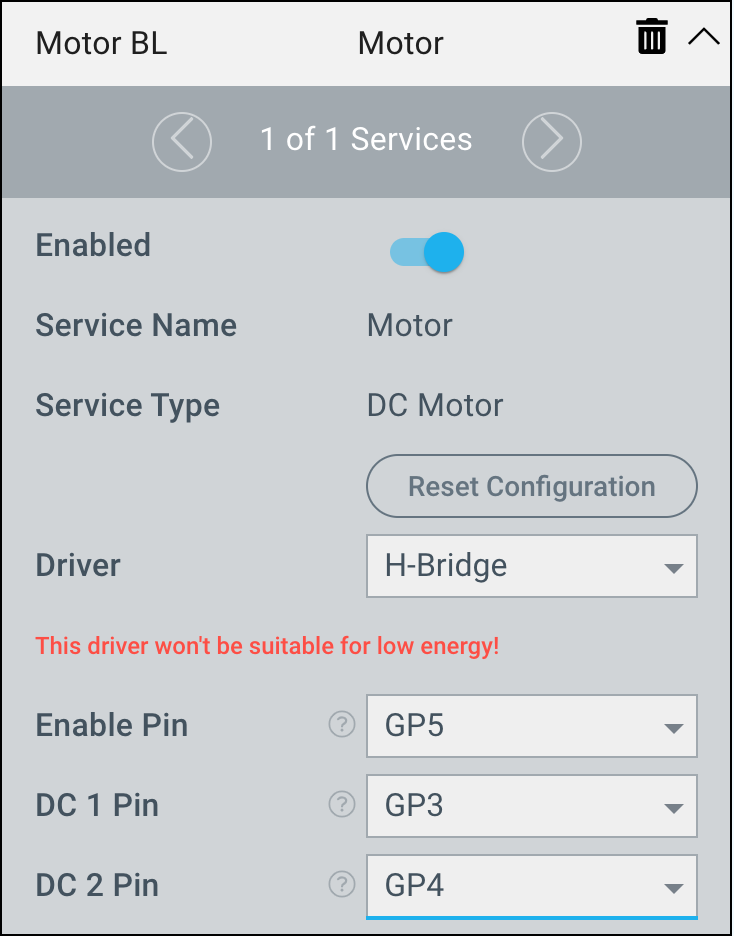
To configure the drivers for the Motor BL device, select the L293D H-Bridge driver from the driver dropdown menu.
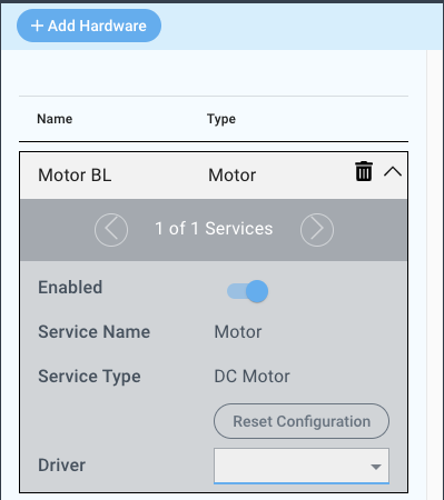
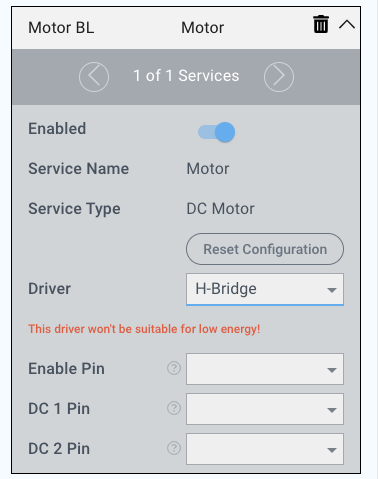
Now, configure the driver as follows:
Enable Pin | DC 1 Pin | DC 2 Pin |
|---|---|---|
GP5 | GP3 | GP4 |
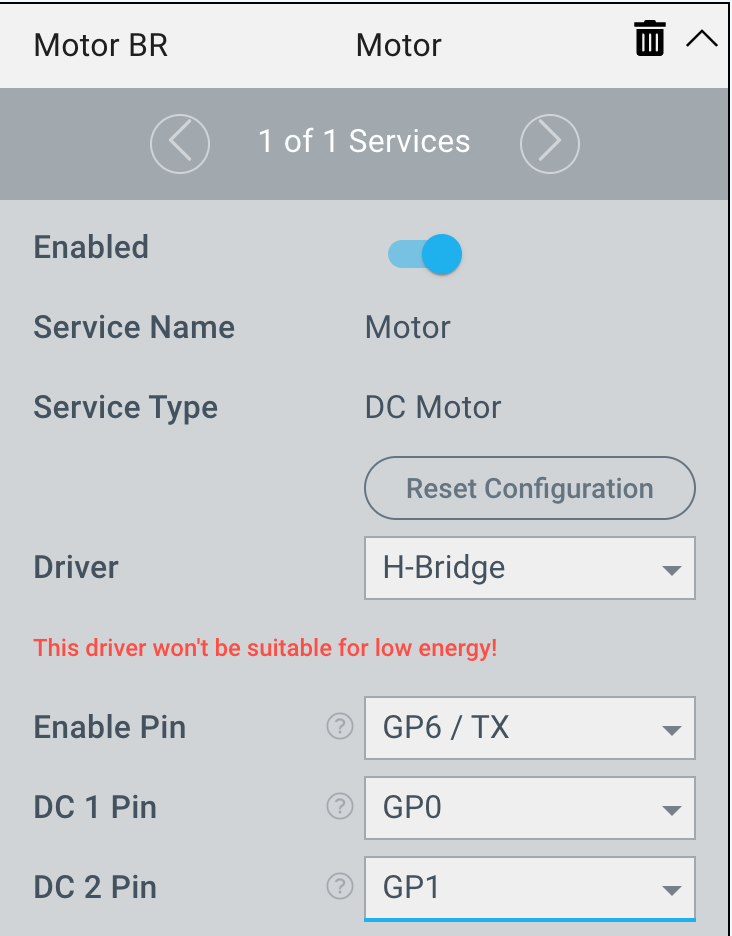
We will now configure the Motor BR driver:
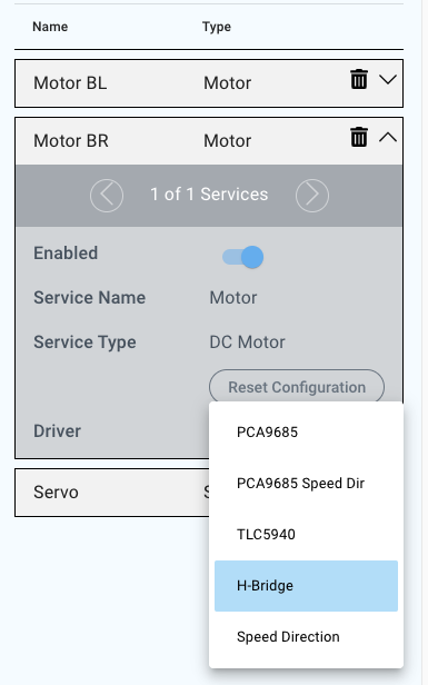
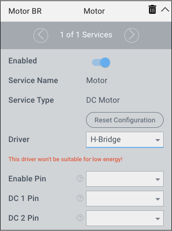
Enable Pin | DC 1 Pin | DC 2 Pin |
|---|---|---|
GP6 | GP0 | GP1 |
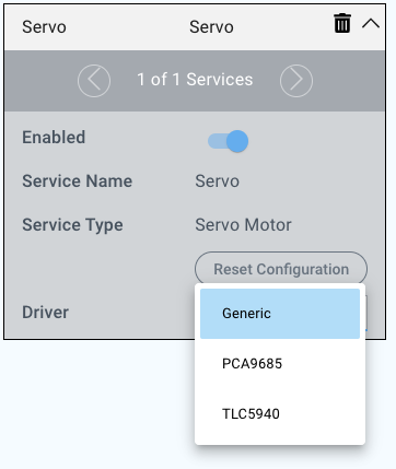
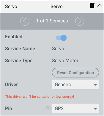
Lastly, we will configure the Servo driver.
Select the Generic driver from the driver dropdown menu

Pin | GP2 |
|---|
That’s it for the firmware! Save your file by clicking the blue “Save” Button at the bottom of the screen.

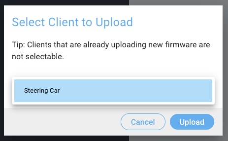
Now you can upload your firmware to the client that you have attached to the Steering Car.
Step 5: Build the Application
| Tip |
|---|
Remember: All Apps and Firmware Files are available in the resources section at the bottom of the page! |
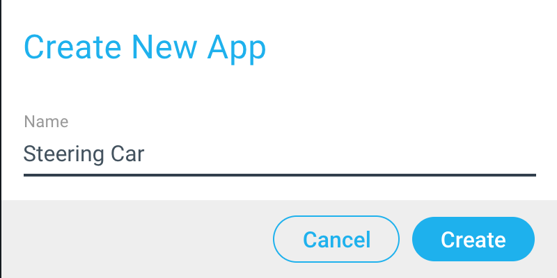
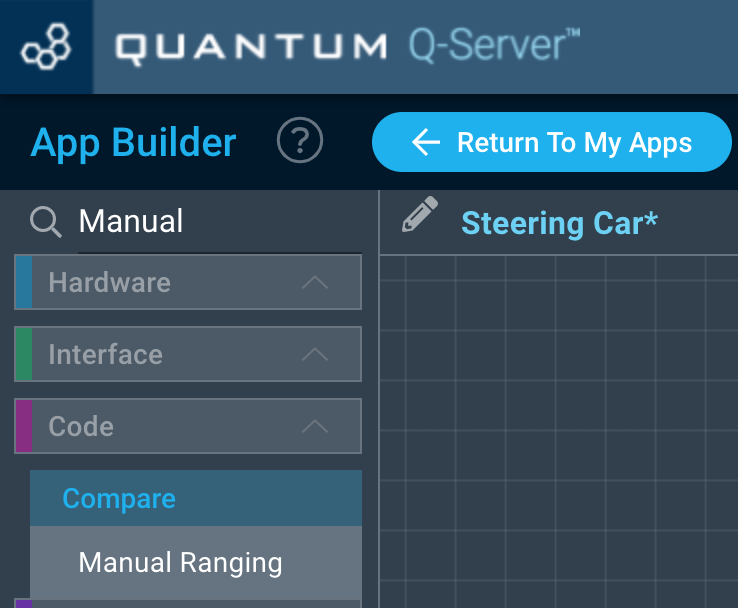
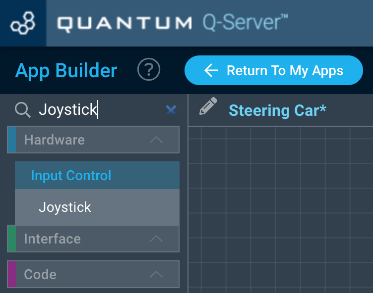
Navigate to the Applications page and click the “+ Create New Button”, name your application, and click create.
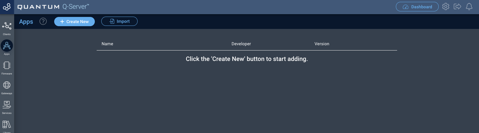
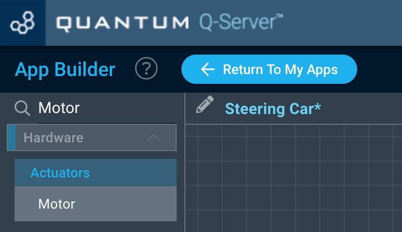
You will now be directed to the App Builder Canvas.
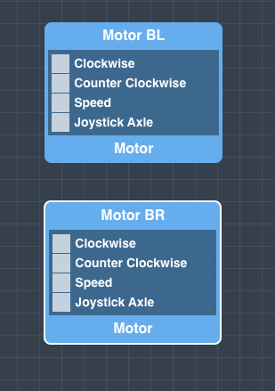
Using the search bar in the left hand tool-bar search for the Motor code object and drag two of them onto the canvas.
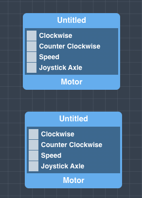
Name the Motor Objects as we do. This will help you to identify the motors during the application mapping. To rename them click on the motor object and change the name in the properties panel on the right.
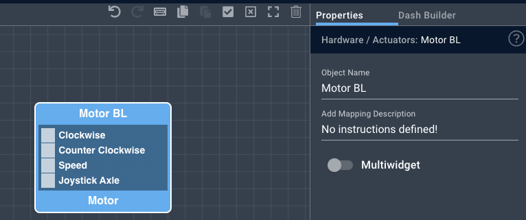
In order to save the names you must click the “Save Properties” button at the bottom of the properties tab.

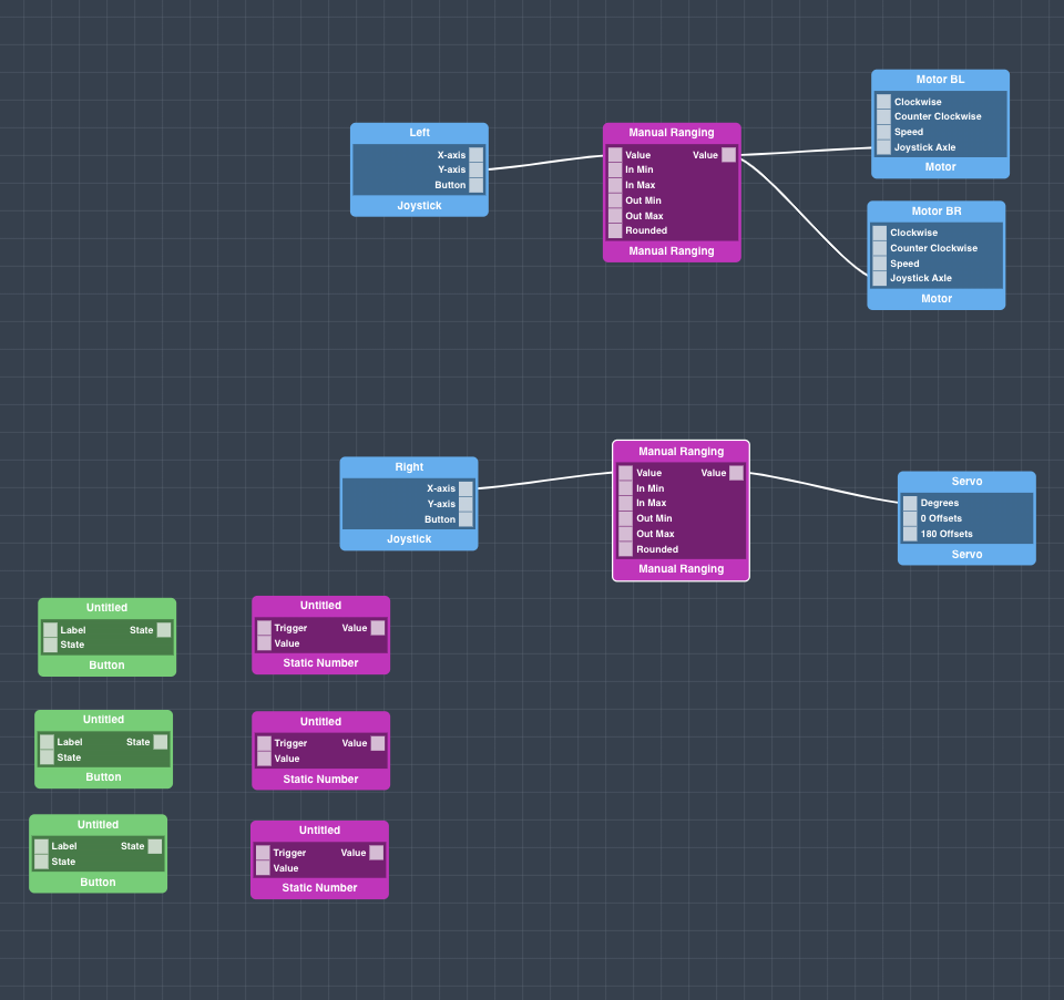
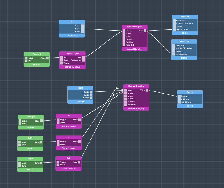
Next, search for and drag a Manual Ranging object onto the canvas.
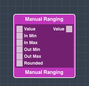
Configure the manual Ranging object as follows:
Value | In Min | In Max | Out Min | Out Max | Rounded |
|---|---|---|---|---|---|
Trigger: on | 0 | 4095 | 0 | 4095 | false |
| Info |
|---|
To configure each port on the object click on the port and change the properties in the properties panel on the right side of the screen, and hit save properties at the bottom of the screen. If you don’t your changes will not be saved! |
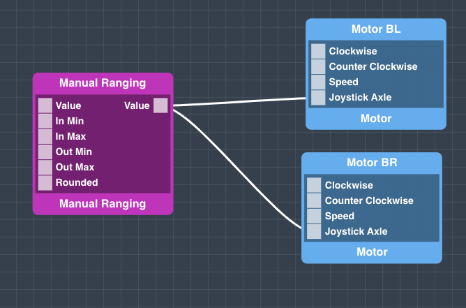
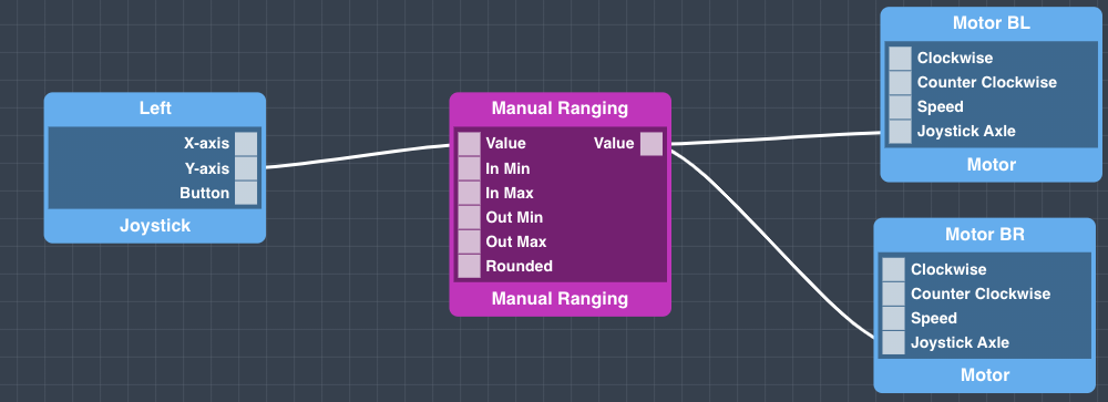
Next, connect the Value out port from the Manual Ranging object to the Motor objects as follows:
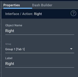
Now search for the “Joystick” object and drag two of them onto the canvas. Name one Left, and the other Right.
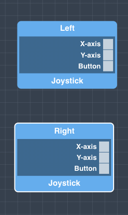
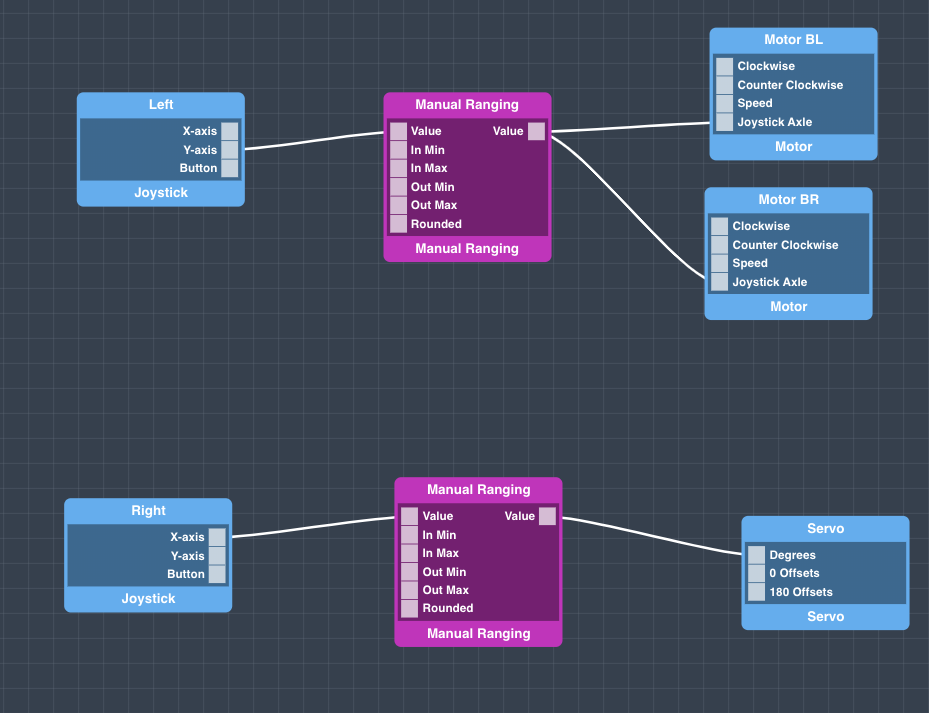
Now connect the Y-Axis port from the Joystick Left object to the Manual Ranging object as follows:
Your steering car will now move forwards and backwards with the left joystick, now we will work on the steering.
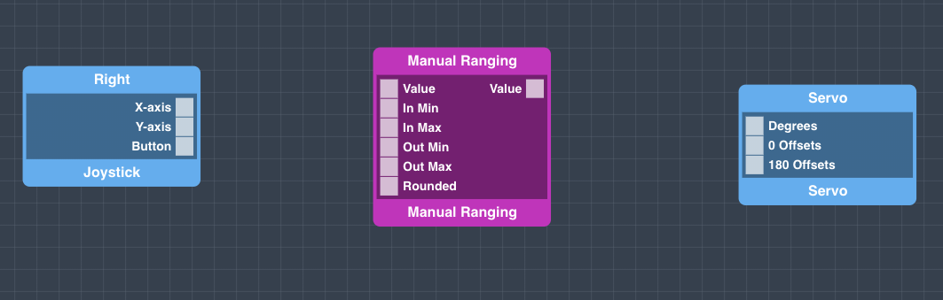
Search for and drag onto the canvas another Manual Ranging object and a Servo object.
We suggest that you name both of these objects.
Configure the ports on the Manual Ranging object as follows:
Value | In Min | In Max | Out Min | Out Max | Rounded |
|---|---|---|---|---|---|
Trigger: on | 0 | 4095 | 180 | 0 | false |
| Info |
|---|
We set the out min as 180 and the out Max at 0 so that when the right joystick is at rest in the centered position 90 will be output by output by the joystick instead of 0. |
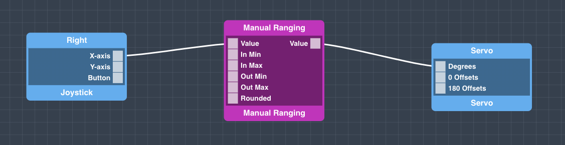
With the Manual Ranging object configured we will connect the code objects as follows:
| Info |
|---|
It is possible that you will have to adjust your 0 and 180 offsets to get the proper range of motion on your servo. If this is the case, you can follow our tutorial on offset adjustment here. |
Your Steering Car is now totally usable with a set of joysticks. However, we will add some code objects that will allow the car to be controlled via the dashboard interface.
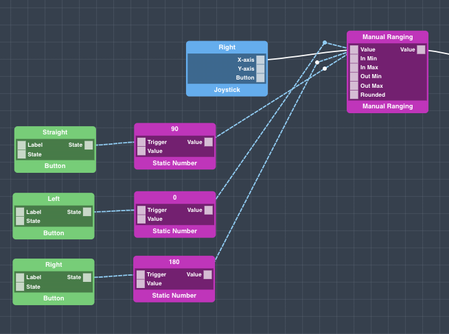
First we will start with steering. Drag three button interface objects and three static number objects onto the canvas. Arrange and name them as shown:
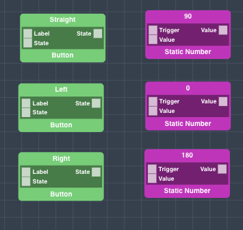
Now, label each of the Button objects to make them easily identifiable on the dashboard. Be sure to save the properties for each button. If you don’t, your changes will be lost!
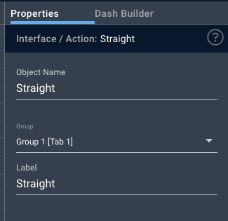
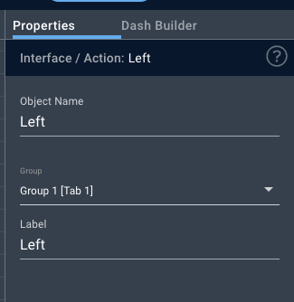
Now make the connections highlighted in blue:
We will now move on to make the car drive forwards using the interface buttons.
Drag a Digital Toggle code object and an interface button onto the canvas. Be sure to name and label the button
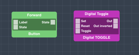
Now make the following connections that are highlighted in blue:
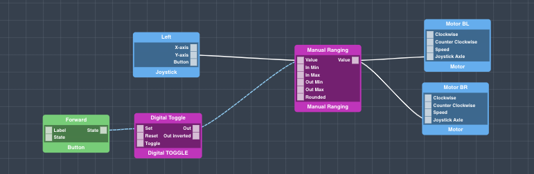
Congrats, your app is now complete!
Hit “Save App” and go back to your applications page.
Step 6: Map Your Application
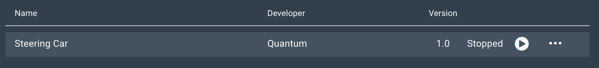
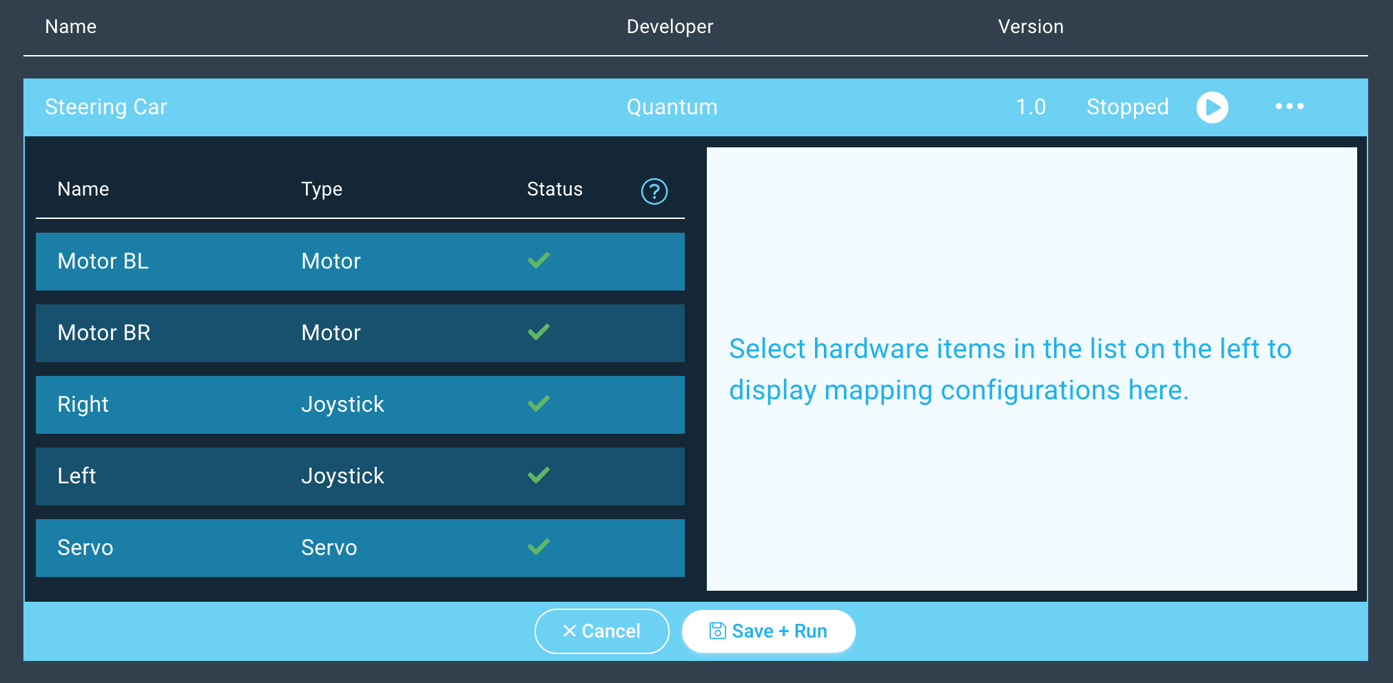
You should now be back on the Apps page.
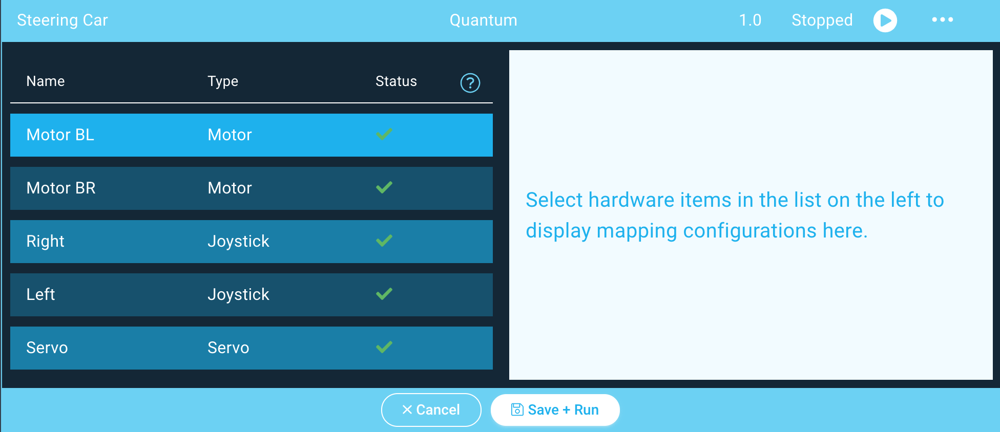
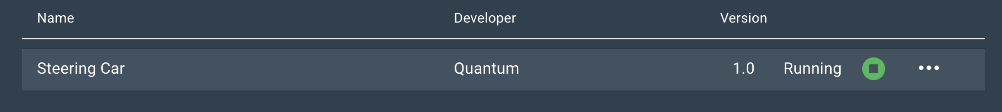
Find your “Steering Car” app and hit the play button.
A list containing all of the devices in your application will expand.
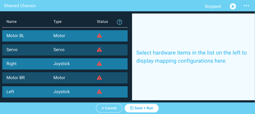
Next click on the “Motor BL” device and the client dropdown menu will appear on the right.
Select the Motor BL driver from the dropdown menu and hit “Done”.
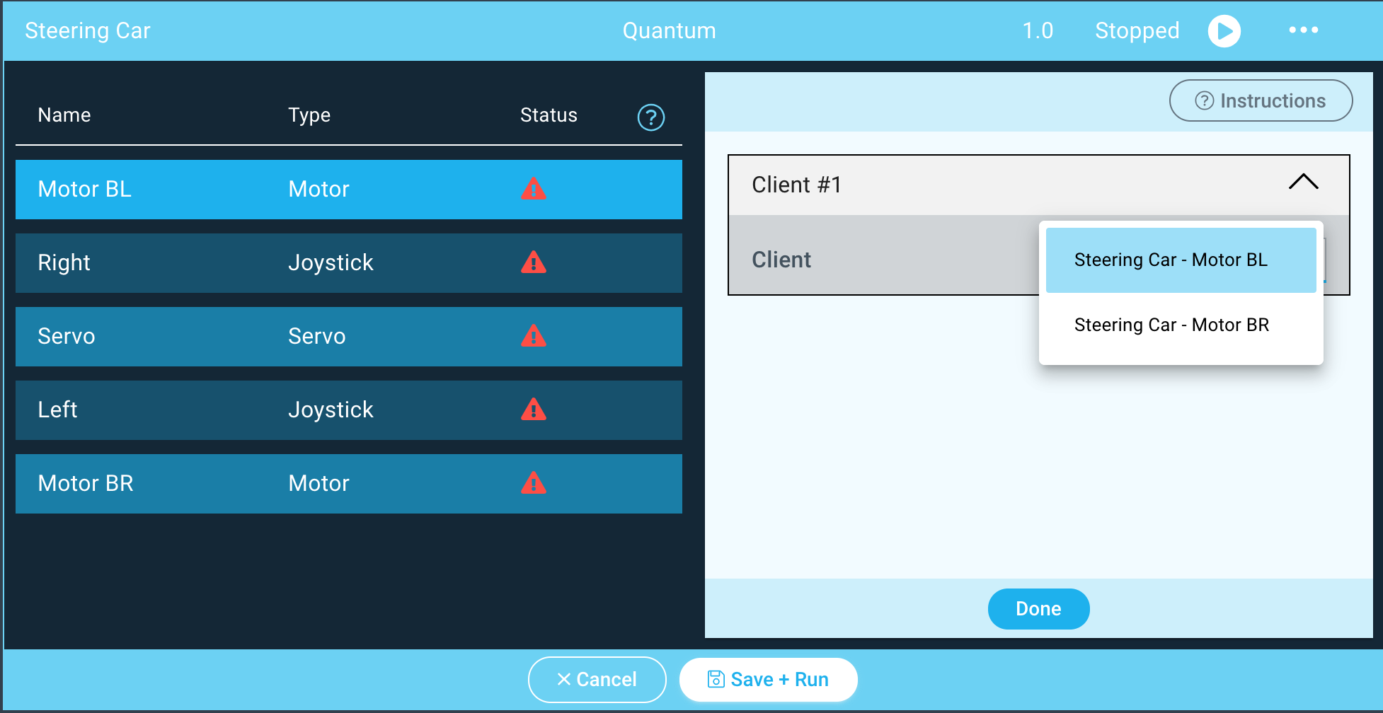
Repeat the same steps for the Motor BR and Servo devices, ensuring that you match the device name to the object name.
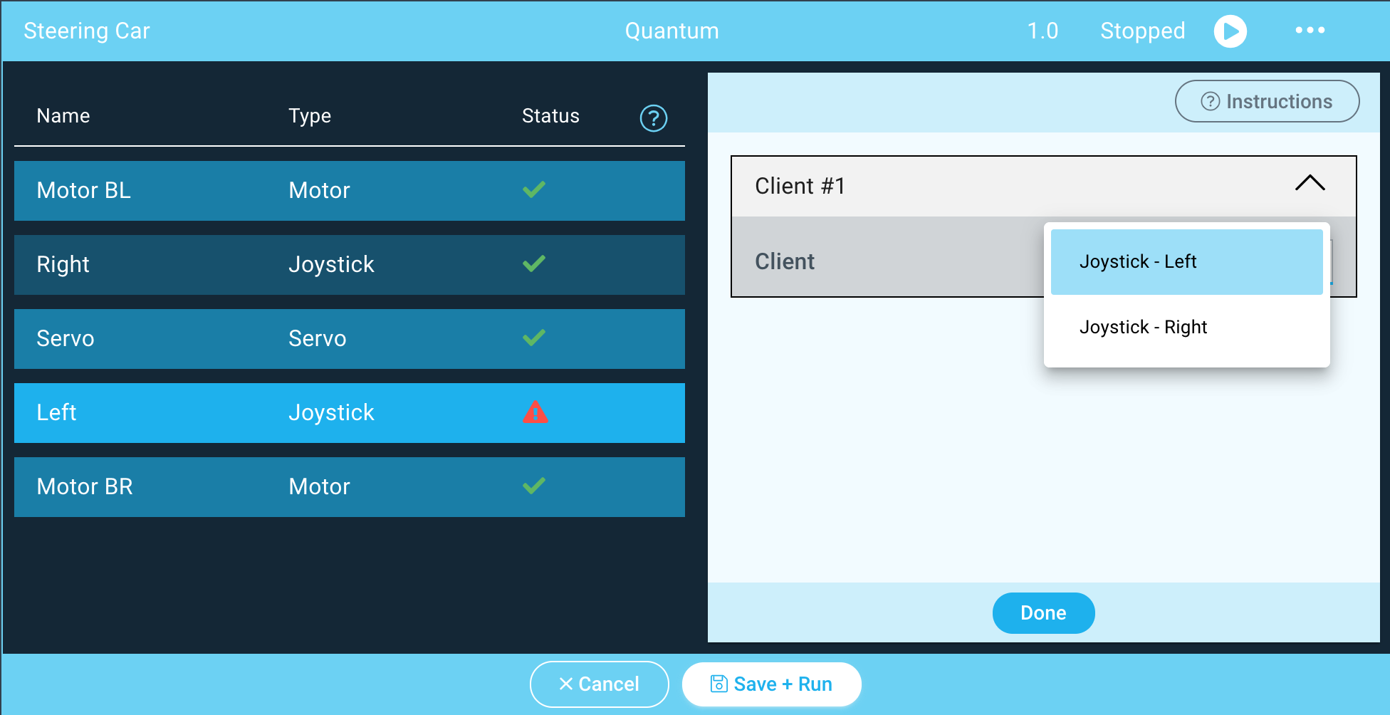
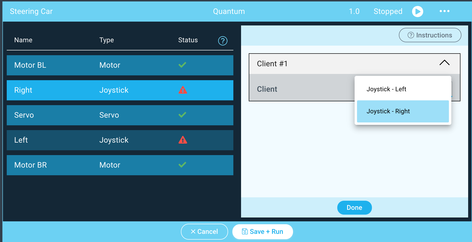
You can map the Joystick Devices in the same way, but make sure that you match the Left and Right Joystick drivers with the Left and Right Joystick devices.
If you have yet to build a Joystick project or DIY kit you can find out how to build them here.
Notice how the status symbols have changed to green checkmarks.
| Info |
|---|
When mapping firmware devices to objects in your Apps it is important to note that only devices and objects of the same type can be mapped together. Using this app for example, we are only given the option to map the client with the button firmware to the button object. |
Step 7: Run the Application!
Next, hit “Save + Run”
Congratulations! Your Steering Car Kit is now complete, have fun!
Code
App
| View file | ||
|---|---|---|
|
Firmware
| View file | ||
|---|---|---|
|
Gallery
Resources
App |
| ||||||||
|---|---|---|---|---|---|---|---|---|---|
Firmware |
| ||||||||
Schematic |
| ||||||||
BOM |
| ||||||||
Gerber Files |
| ||||||||
Final Rev C |
|