| Table of Contents |
|---|
Introduction
The Speed Direction driver is used in conjunction with an H-bridge IC (integrated circuit) and some inversion logic, or just a breakout board featuring the control, like the Sunfounder motor driver. The speed pin regulates the speed of the motor and whether it is operating at all while the direction pin is controlling the polarity of the motor. The direction pin is digital, that means it always has a direction determined, so the only way to make the motor stand still is to set the speed to 0.
Driver Parameters
The Speed Direction driver for motors has two parameters that need to be configured:
Speed Pin
The speed pin is driving the speed with a pulse width modulated signal. It is either connected to the enable signal of an H-Bridge or the dedicated pin of a breakout board.
Direction Pin
The direction pin is controlling the polarity of the motor. It is either connected to one in pin of an H-Bridge with an inverted signal connected to the other in pin or to a dedicated pin on a breakout board.
Wiring
We can use the two widely used H-Bridge ICs like the L293D from multiple suppliers and the SN754410 from Texas Instruments and some inversion logic, like a not gate. Their pinout can be seen below:
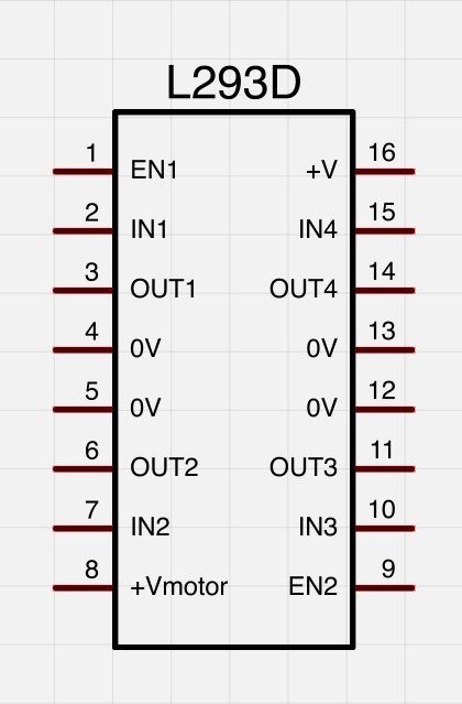
Some important facts about the chip:
all 0V (GND) pins should be connected, since they also dissipate the heat from the chip
pin 16 (+V) should be at 5V to provide proper functionality while pin 8 (+Vmotor) can be anything between 3.5V and 12V
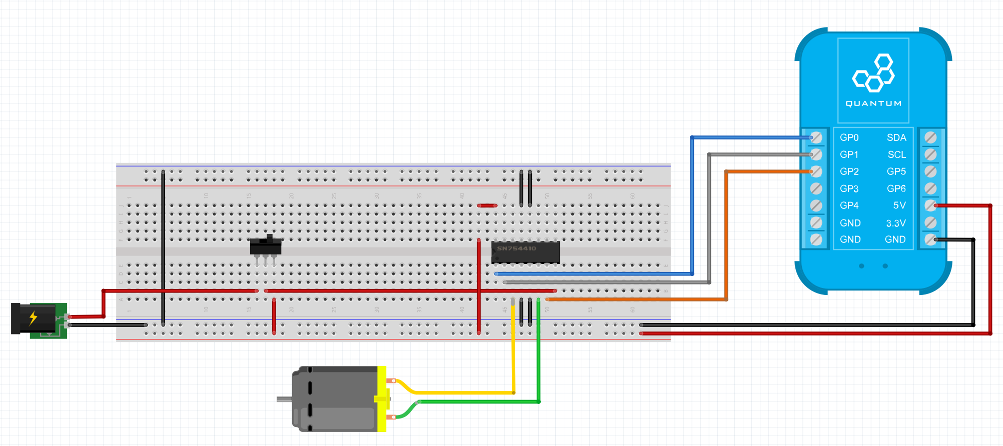
Or we can use a board that already features the inversion and just offers the speed direction pins broken out to us, like the Sunfounder motor driver.
Example
From the Builder Base the GP0 pin is connected to Enable Pin, the GP1 Pin is connected to the DC 1 Pin and also to the gat of an NPN transistor. The transistor inverts the signal and connects to the DC 2 pin, the 5V and GND pins on the Builder Base are then connected to the VCC and GND pins on the H-Bridge. We see that there is a switch, that can either switch our motor voltage to the 5V output of the Builder Base or to anything we want to supply with the barrel jack (3.5V - 12V).
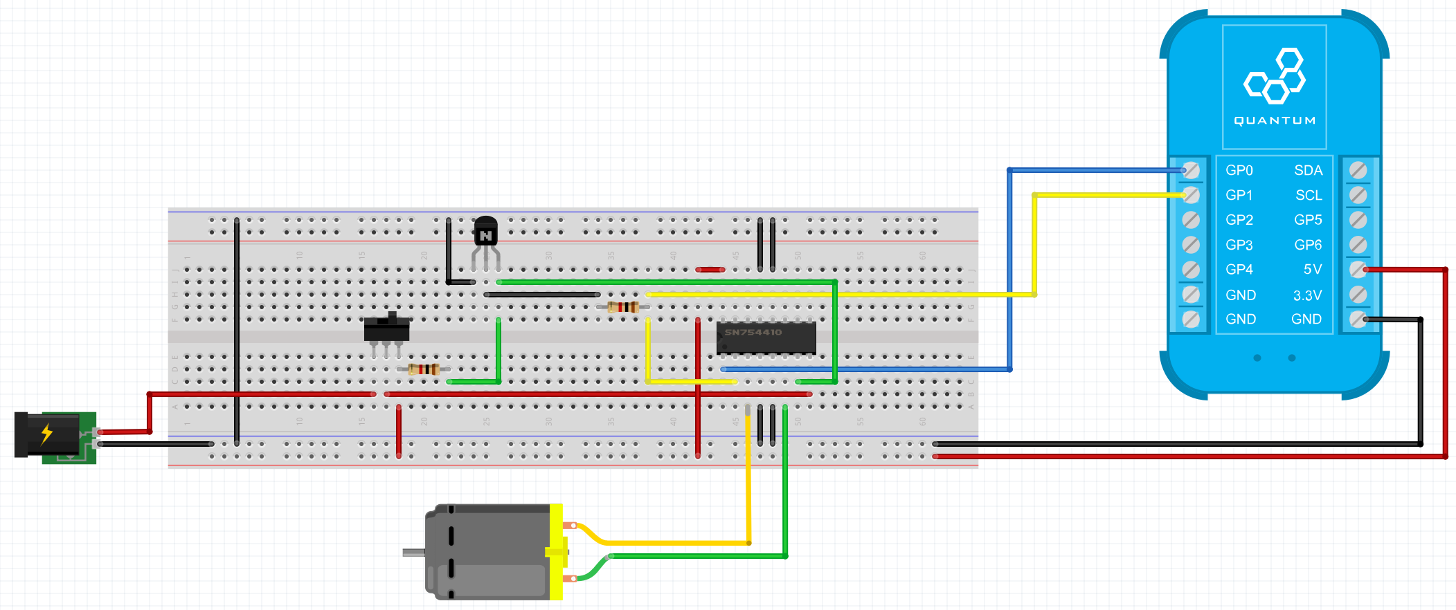
Breadboard
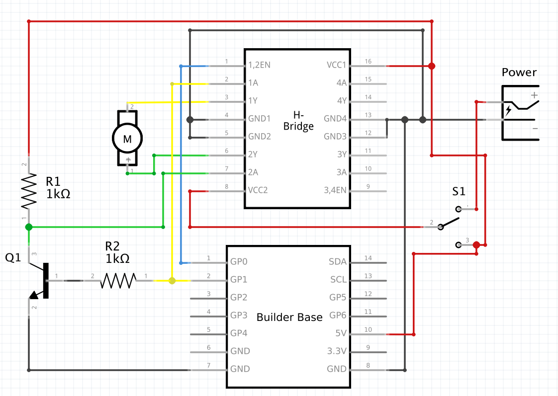
Schematic
Used Pins
Used Pins | Description |
|---|---|
GP0 (can be any GP pin) | Connected to Speed Pin |
GP1 (can be any GP pin) | Connected to Direction Pin |
5V | This pin provides the power |
GND | This pin provides the GND |
How to write an App
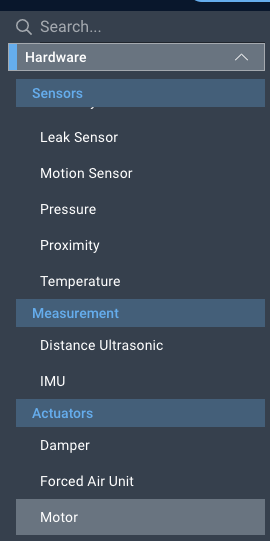
Navigate to the App Builder and create a new application. You can find the “Motor” code object under the “Hardware” Tab in the object drop down menu on the left, or you can also use the search bar.
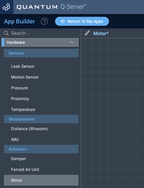
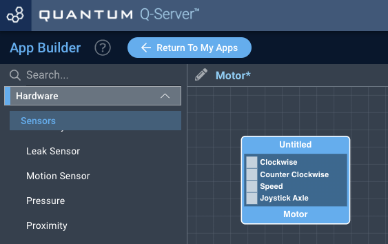
Drag the “Motor” object onto the grid.
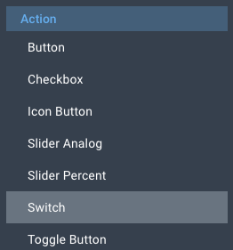
Next, under the interface tab, locate the switch, slider percent, and slider analog interface objects. Next, drag two of the switch objects, a slider percent object, and slider analog object onto the grid.
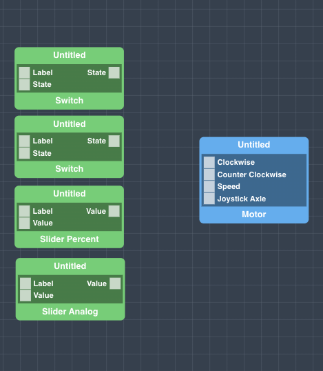
Finally, connect a switch object to each the clockwise and counter clockwise ports on the motor object, connect the slider percent object to the speed port, and the Slider Analog to the Joystick Axle. For the sake of organization, label each of the interface objects, and save your application.
How to create a firmware
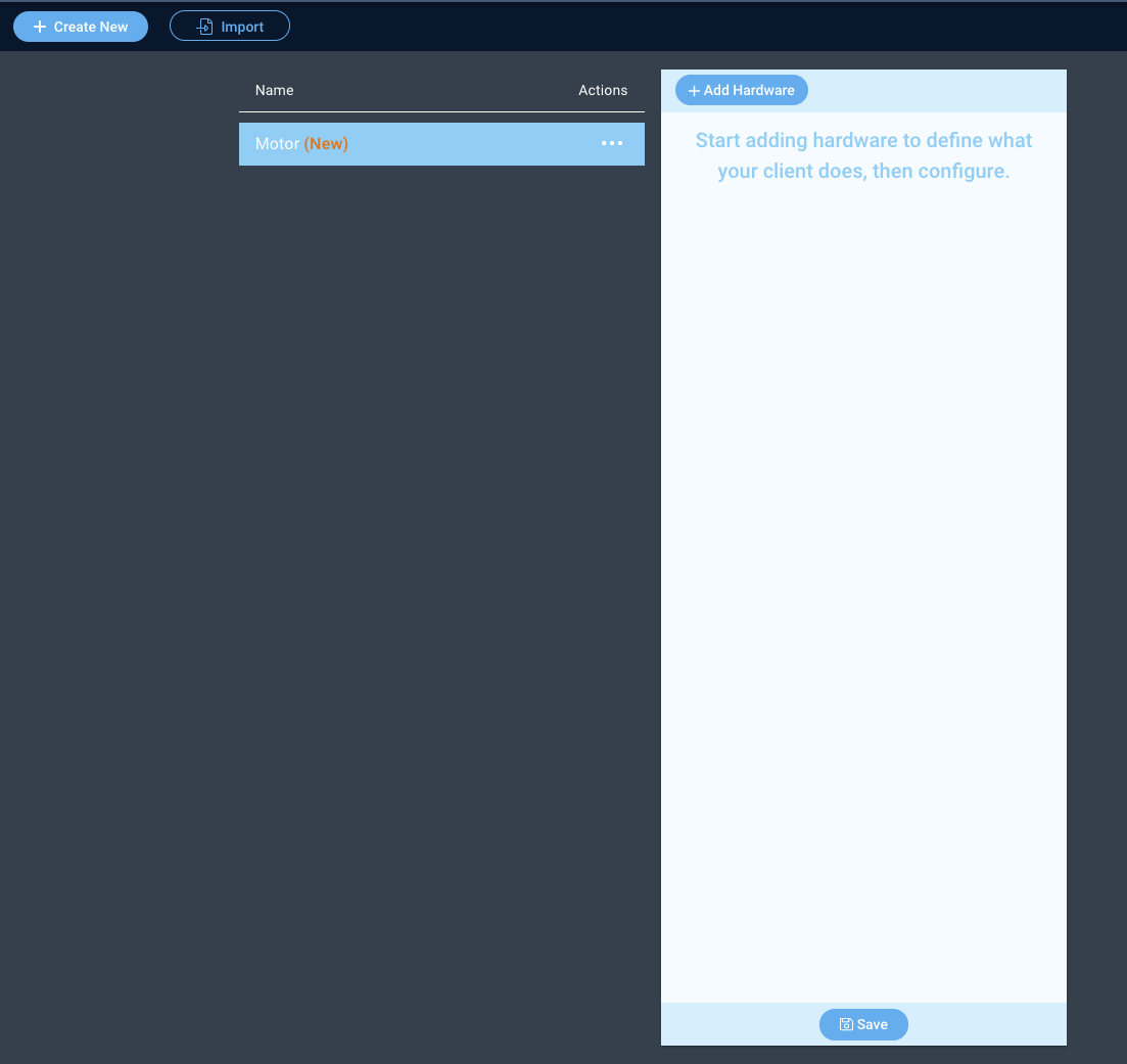
Navigate to the Firmware Builder and create a new firmware file.
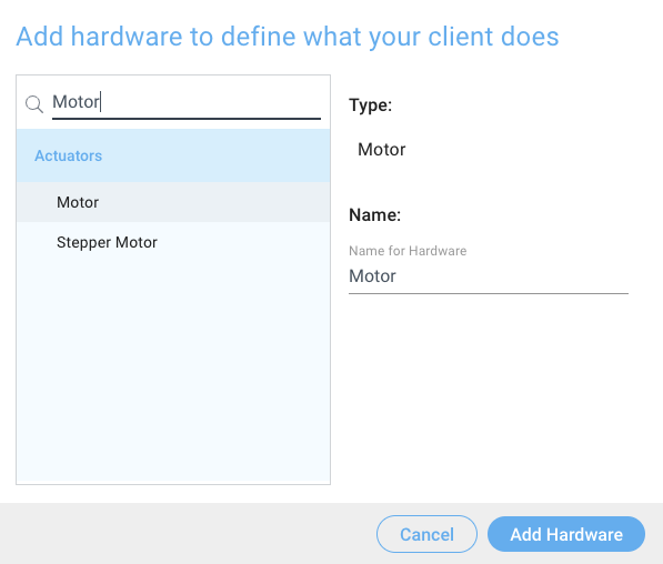
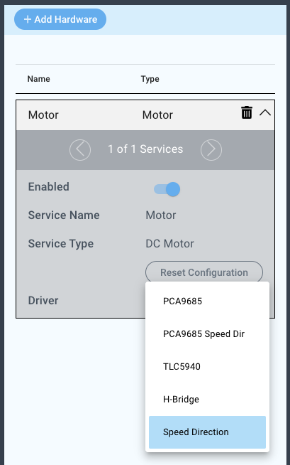
Click the “+ Add Hardware” button and listed under the “Actuators” tab find the “Motor” hardware option.
Give your device a name, and click “Add Device”
Next, select the “MPU3050” under the driver dropdown menu.
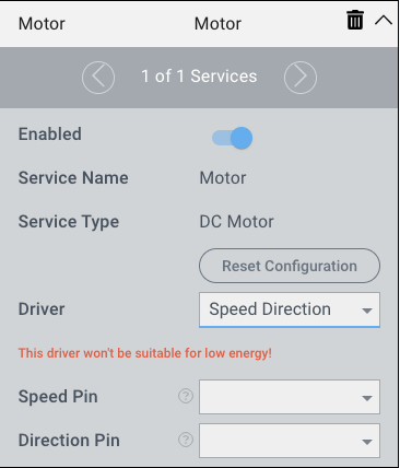
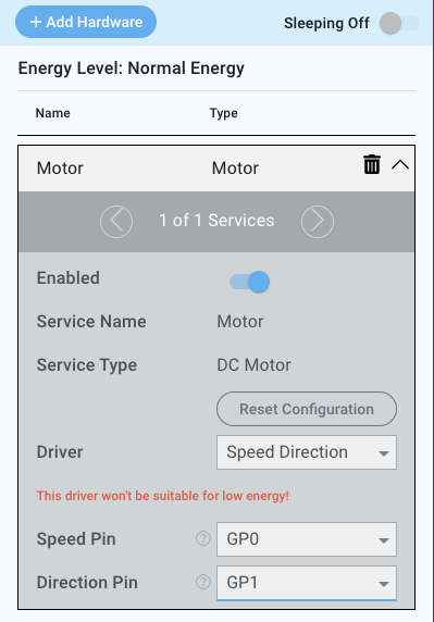
For this example we select:
Speed Pin: GP0
Direction Pin: GP1
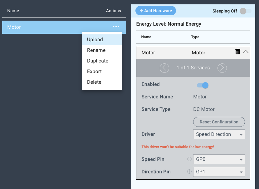
You may now save your firmware file and upload it to one of your clients.
Supported Hardware
H-Bridge
Motors
Servos
Other Actuators
Downloads
Apps
| View file | ||
|---|---|---|
|
Firmware
| View file | ||
|---|---|---|
|
Assets