| Table of Contents |
|---|
Overview
| Widget Connector | ||||||||||
|---|---|---|---|---|---|---|---|---|---|---|
|
| Info |
|---|
For Fullscreen: https://www.youtube.com/watch?v=vScvRFwOoLA |
In order to fully encompass the Smart Home offerings from our quantum system, we thought it necessary to create a HVAC system. This is only the prototype of our HVAC system and many revisions will be made and additions added before we consider this project finalized. The HVAC - 1 Zone project consists of a display, rotary encoder and 3 status led lights, and can be used as a means to control heating and cooling for a room. In future revisions we will add multi-zone heating and cooling. Regardless, here’s a peek at what we’ve been working on. Follow along and build one yourself if you’d like a smart HVAC system of your own!
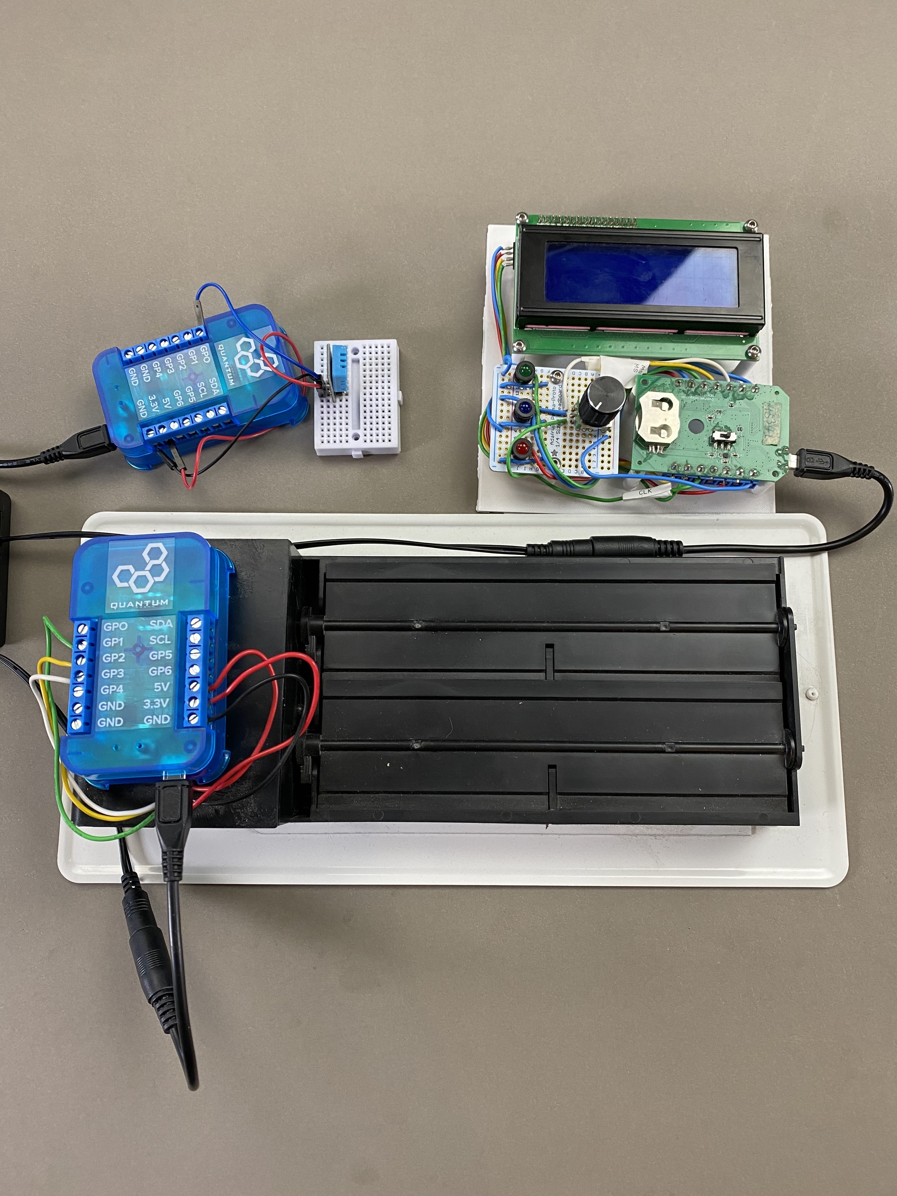
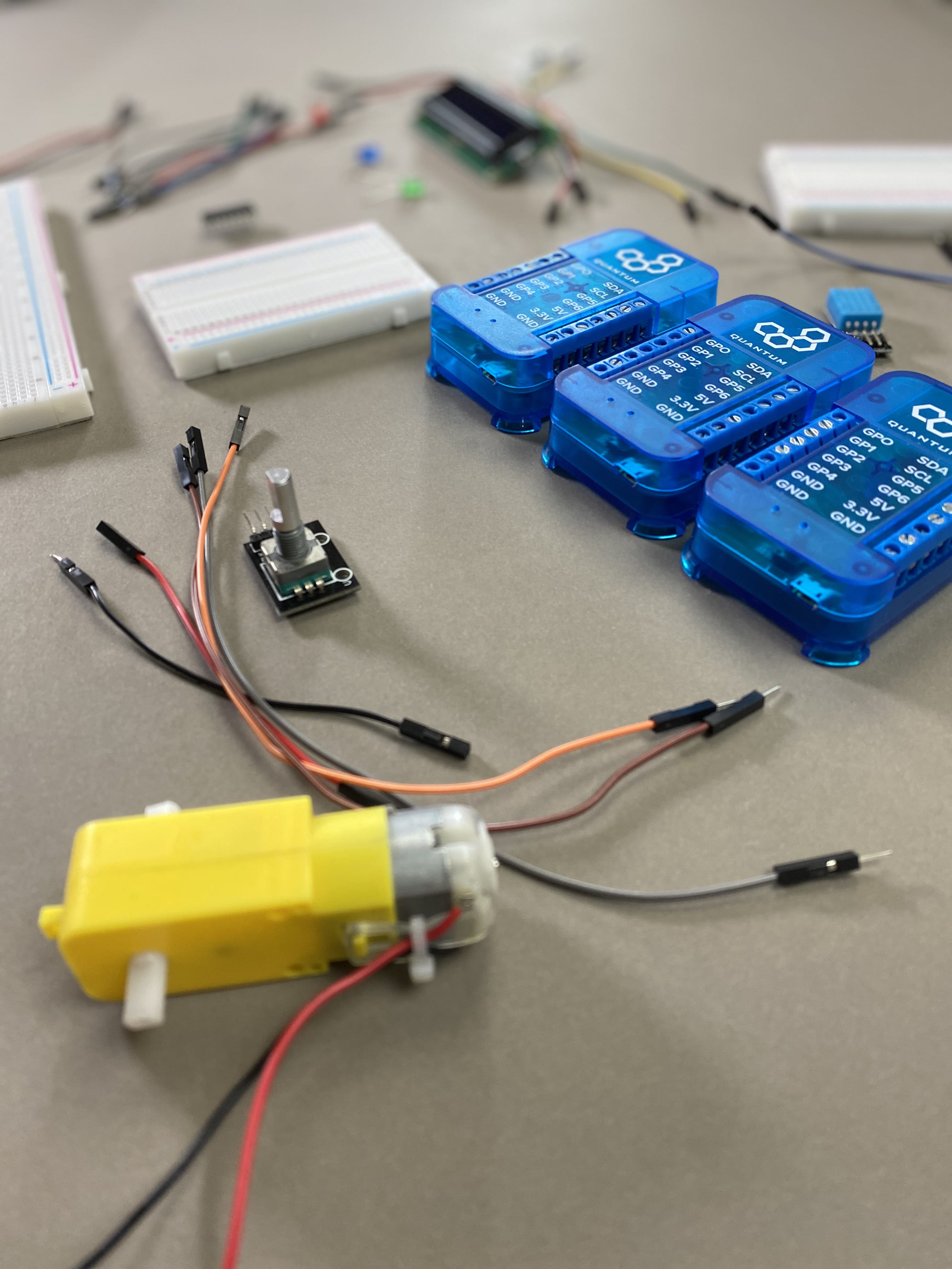
The control unit is just some hardware hooked up to one client and mounted on a 3D printed board. The hardware consists of:
LCD2004 (I2C)
3 LEDs (1 GPIO each)
Rotary encoder (3 GPIOs)
|
|
|
|
|
|
|
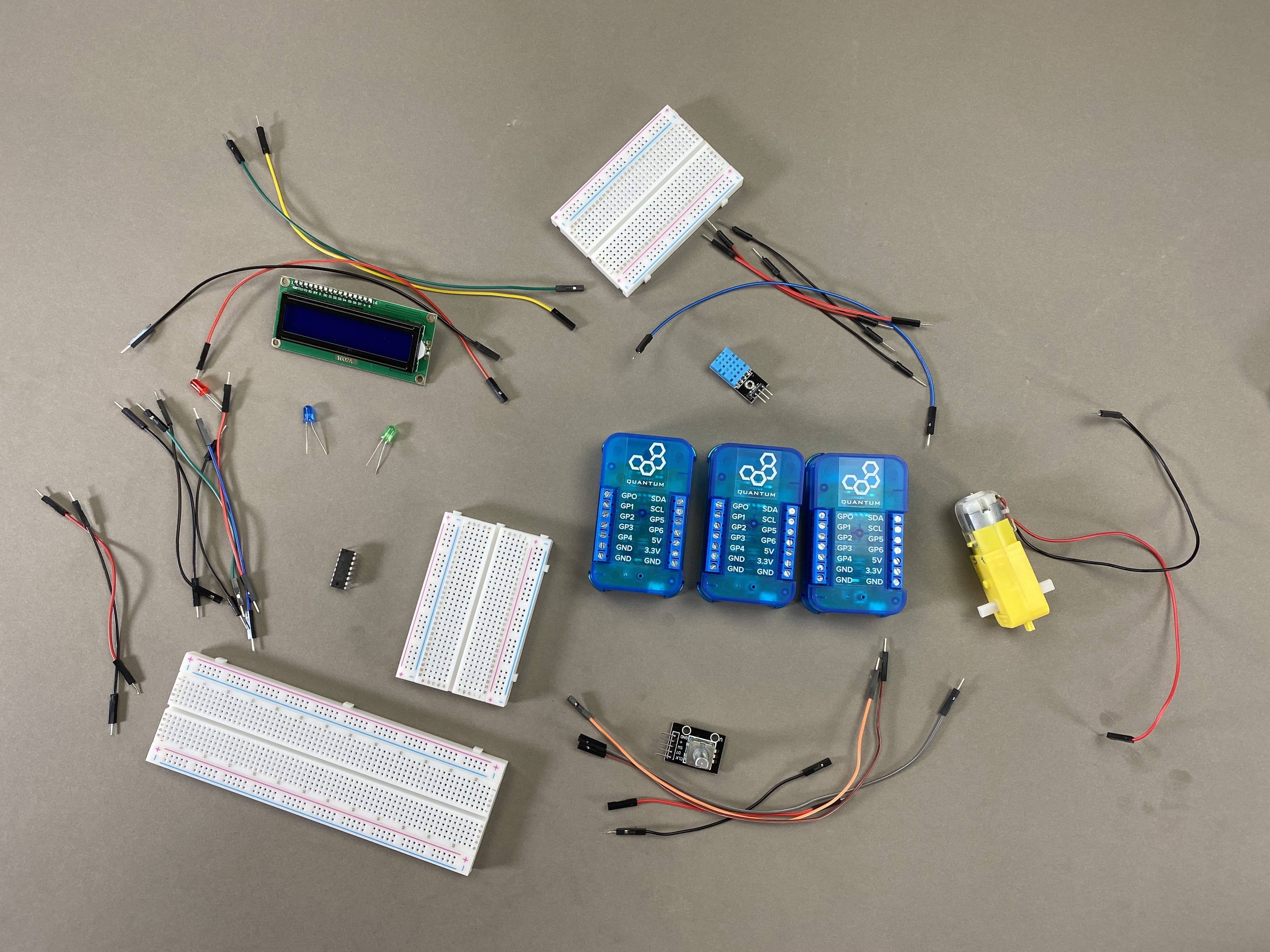


Things used in this project
Hardware Components
Picture | Name | Quantity | Link |
|---|---|---|---|
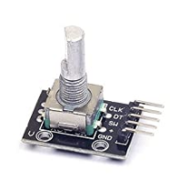 | Rotary Encoder | 1 | Included in |
Or you can purchase it here | |||
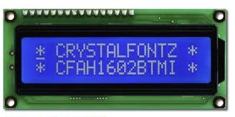 | I2C LCD Display | 1 | Included in |
Or you can purchase it here | |||
 | Green Radial LED (5mm) | 1 | Included in |
Or you can purchase it here | |||
 | Blue Radial LED(5mm) | 1 | Included in |
Or you can purchase it here | |||
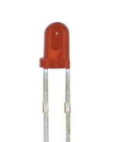 | Red Radial LED(5mm) | 1 | Included in |
Or you can purchase it here | |||
 | Damper with motor | 1 | Can be purchased here |
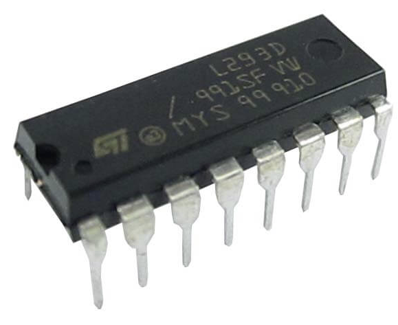 | L293D H-Bridge | 1 | Included in |
Or you can purchase it here | |||
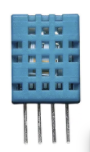 | DHT11 temperature sensor | 1 | Included in |
Or you can purchase it here | |||
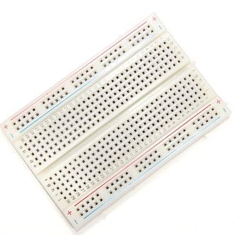 | Breadboards | 3 | Included in |
Or you can purchase it here | |||
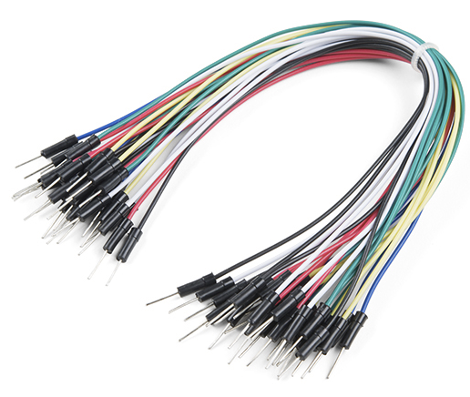 | Male to Male and Male to Female jumper wires | ~20 | Included in |
Or you can purchase it here | |||
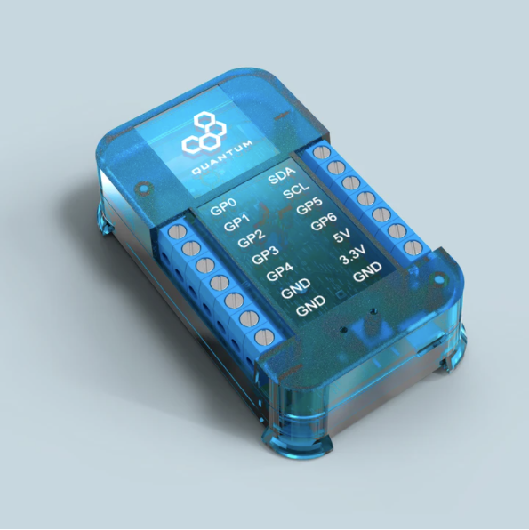 | Q-Client Builder Base | 3 |
Tools Used
Picture | Name | Quantity | Link |
|---|---|---|---|
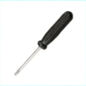 | Small slotted-head screwdriver | 1 | Included in the |
or you can pick from one on our Recommended Tools List |
Story
In order to fully encompass the Smart Home offerings from our quantum system, we thought it necessary to create a HVAC system. This is only the prototype of our HVAC system and many revisions will be made and additions added before we consider this project finalized. Regardless, here’s a peek at what we’ve been working on. Follow along and build one yourself if you’d like a smart HVAC system of your own!
Video
| Widget Connector | ||||||||||
|---|---|---|---|---|---|---|---|---|---|---|
|
Process
Step 1: Building the Hardware
Assemble the Circuits
Gather all of the materials listed in the parts list above. We will start with the simplest circuits and build our way up to the harder ones (DHT11 → Damper → Control Unit).
The DHT11 circuit is by far the simplest circuit to assemble for this build. You will only need 1 Builder Base, 5 MM jumper wires, and a DHT11 temperature sensor.
Use the schematic and breadboard views listed below as a reference.
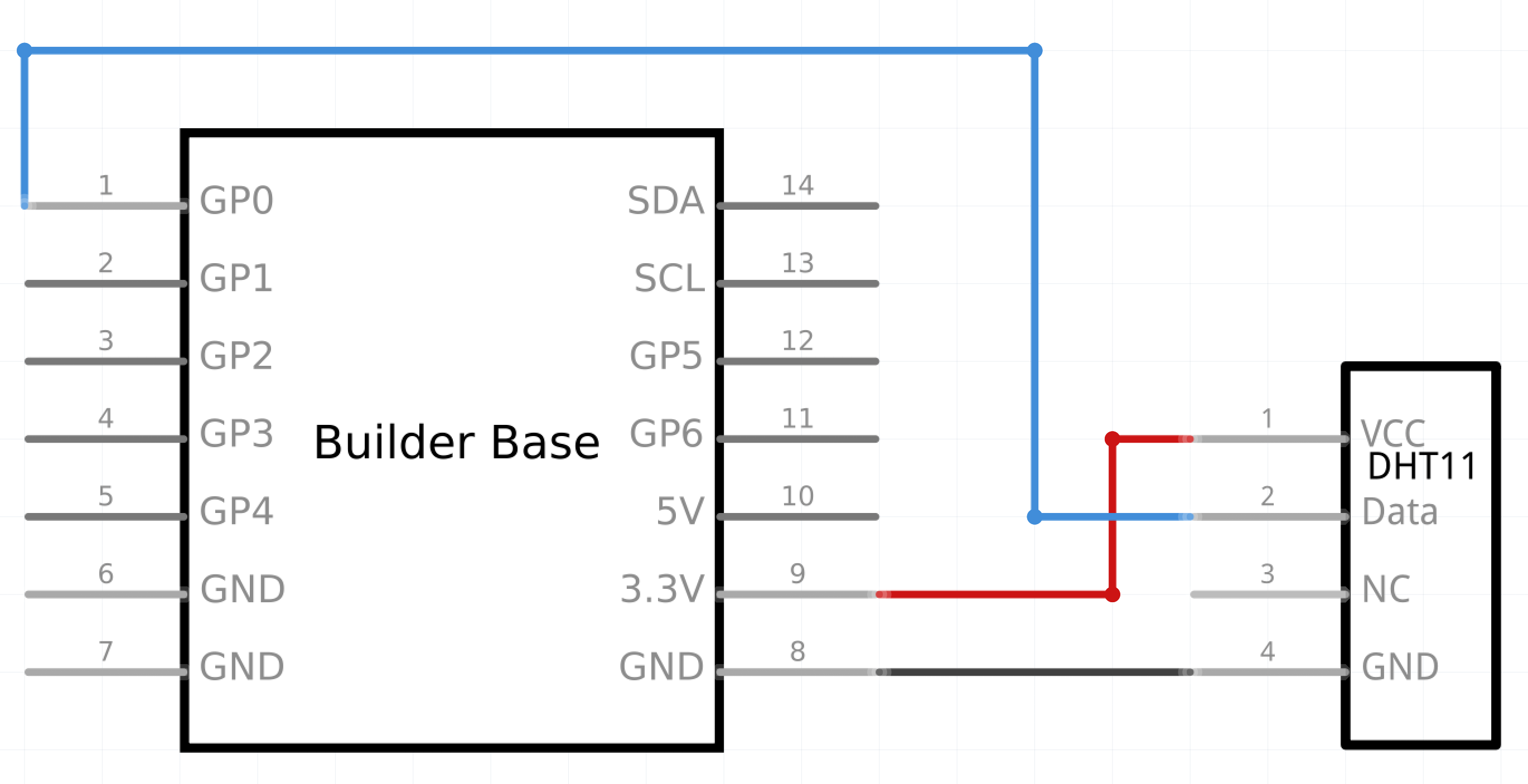
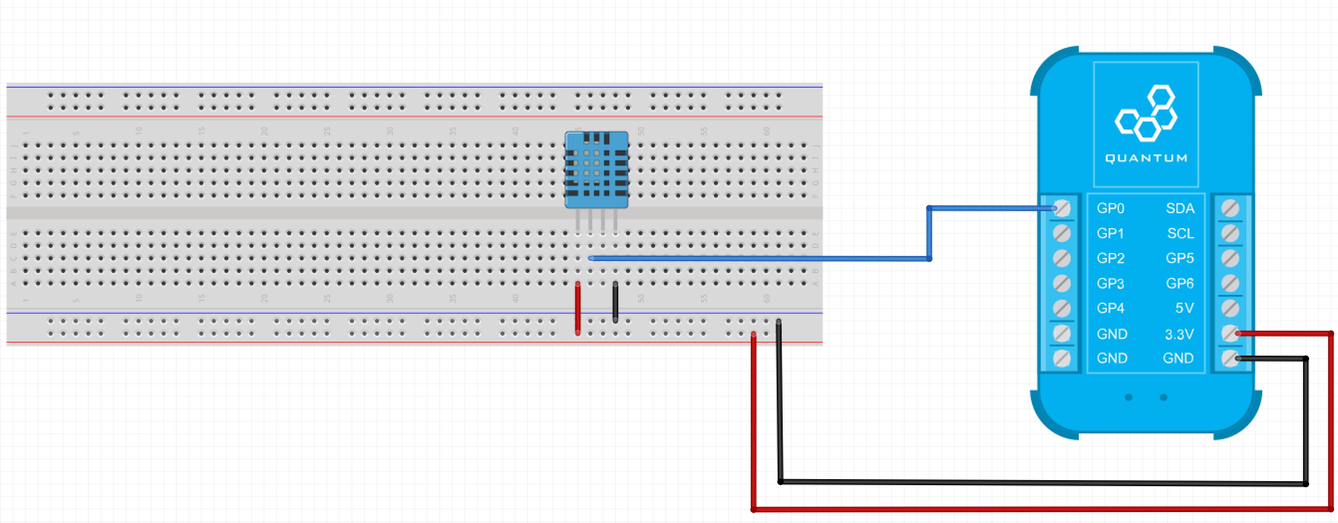


Start by attaching the 3.3V and GND ports on the breadboard to the GND and VCC rails on the breadboard.
Place your DHT11 on the breadboard and attach a jumper from the 3.3V rail to the furthest left pin on the DHT11. Next attach a wire from the GND rail on the breadboard to the furthest right pin on the DHT11.
Lastly, connect the pin second from left on the DHT11 to the GP0 port on the Builder Base.
Your DHT11 circuit is now finished. This will be used to sense the temperature of your heating/cooling zone.
Now let’s assemble the damper circuit. The damper is the vent that is open and closed depending wether the system is heating or cooling. You will need 1 builder base, an L293D H-bridge, a DC motor, and a number of MM jumper wires.
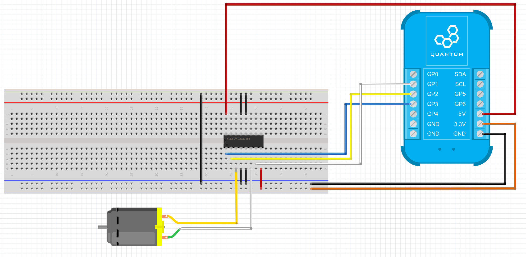
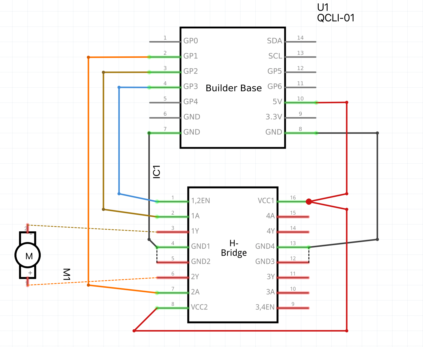
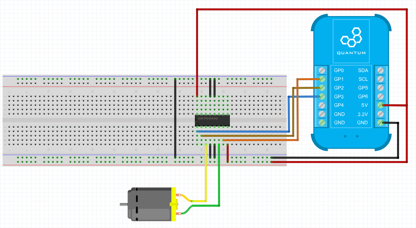
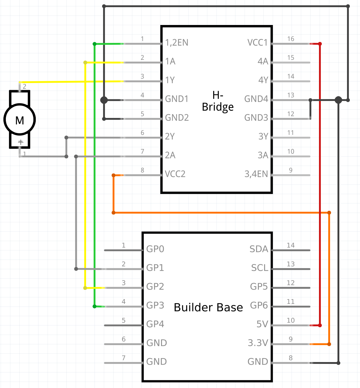
Wire the H-bridge to the Builder Base as follows:
H-Bridge | Builder Base |
|---|---|
1,2 Enable | GP3 |
1A | GP2 |
2A | GP1 |
VCC2 | 3.3V |
VCC1 | 5V |
GND1,2,3,4 | GND |
We then wired the Motor to the H-bridge as follows:
Motor | H-Bridge |
|---|---|
+ terminal | 1Y |
- terminal | 2Y |
We purchased a motorized damper and modified it by bypassing its ECU and connecting it directly to our system using the above circuit . You should be able to do the same with any motorized damper that you purchase, but you need to make sure that the motor used in the damper is a brushed DC motor. Otherwise, you will have to design a circuit that differs from the one above. 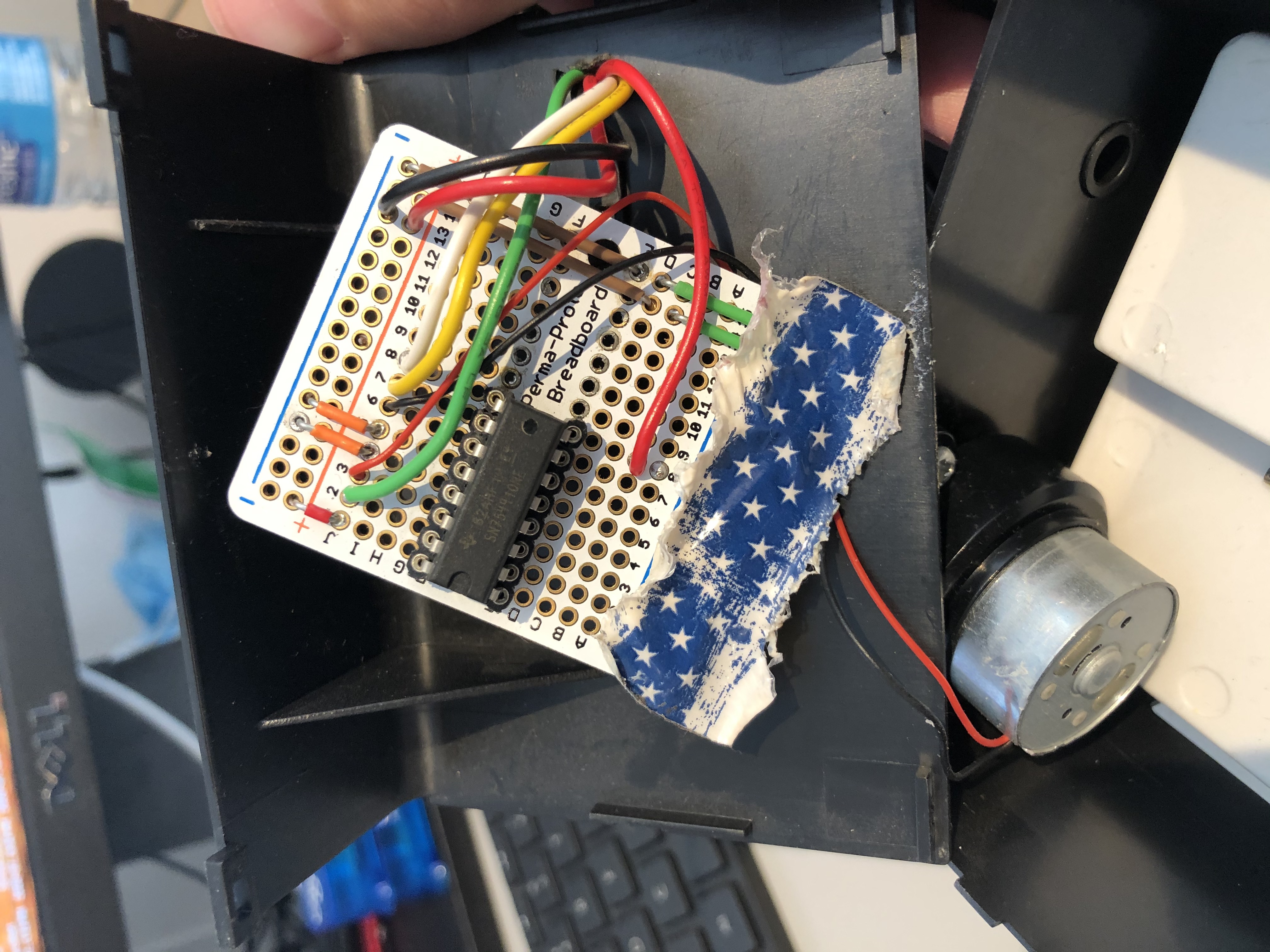
In the video we built the damper circuit without the damper attached. We did this so it would be easier to show you exactly how the circuit is assembled. Here is a photo of the internals of our damper. You can see that the circuit we use is the same. 

With the circuit in place inside of the damper we then chose to cut a hole in the back of the damper and run the wires through it.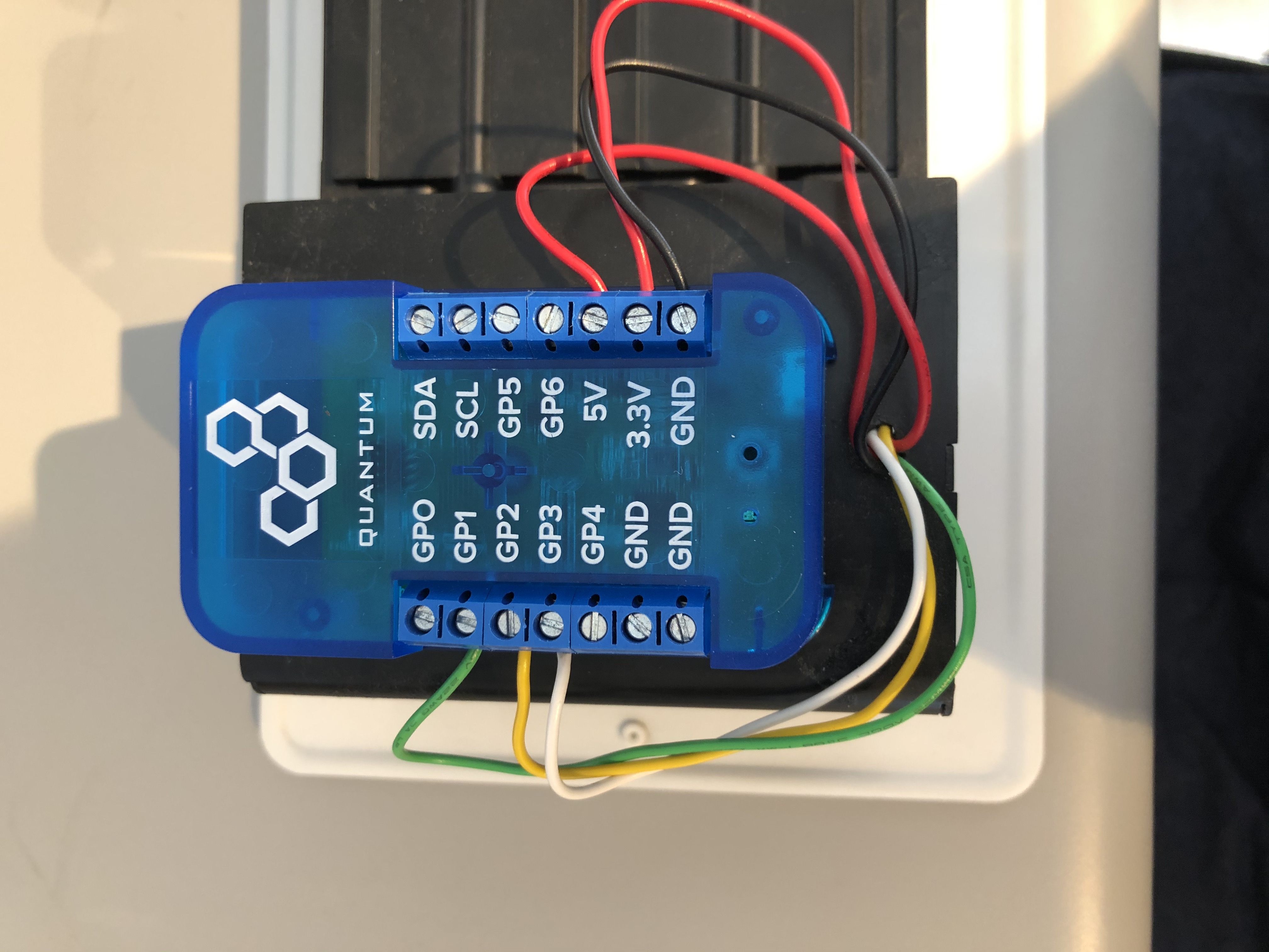
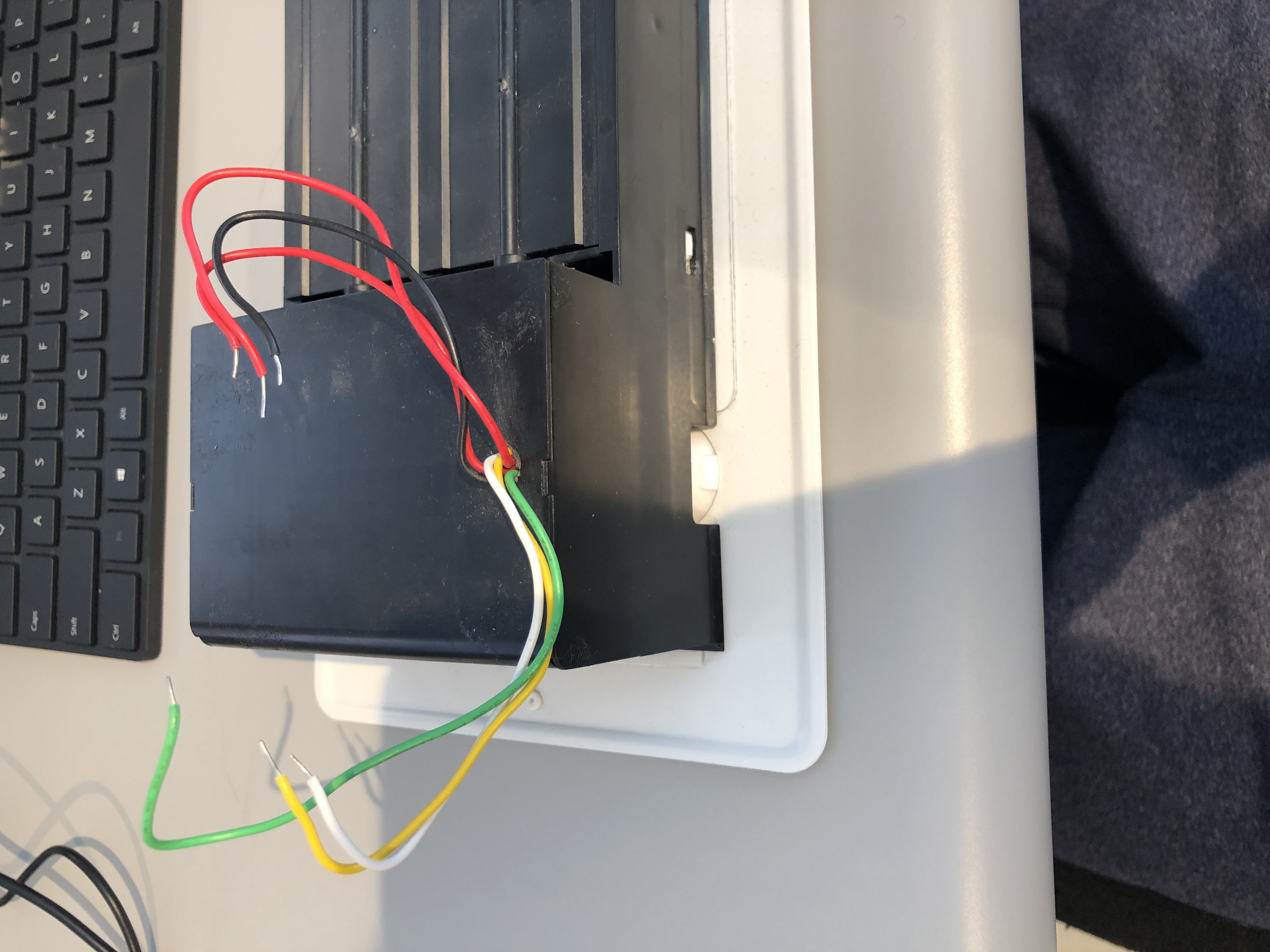
And here it is wired to the client.

The damper circuit is now complete. Let’s move onto the Control Unit.
| Info |
|---|
Note: All of the following electronics are connected to one builder base. We split the diagrams up to make the wiring process easier to follow. |
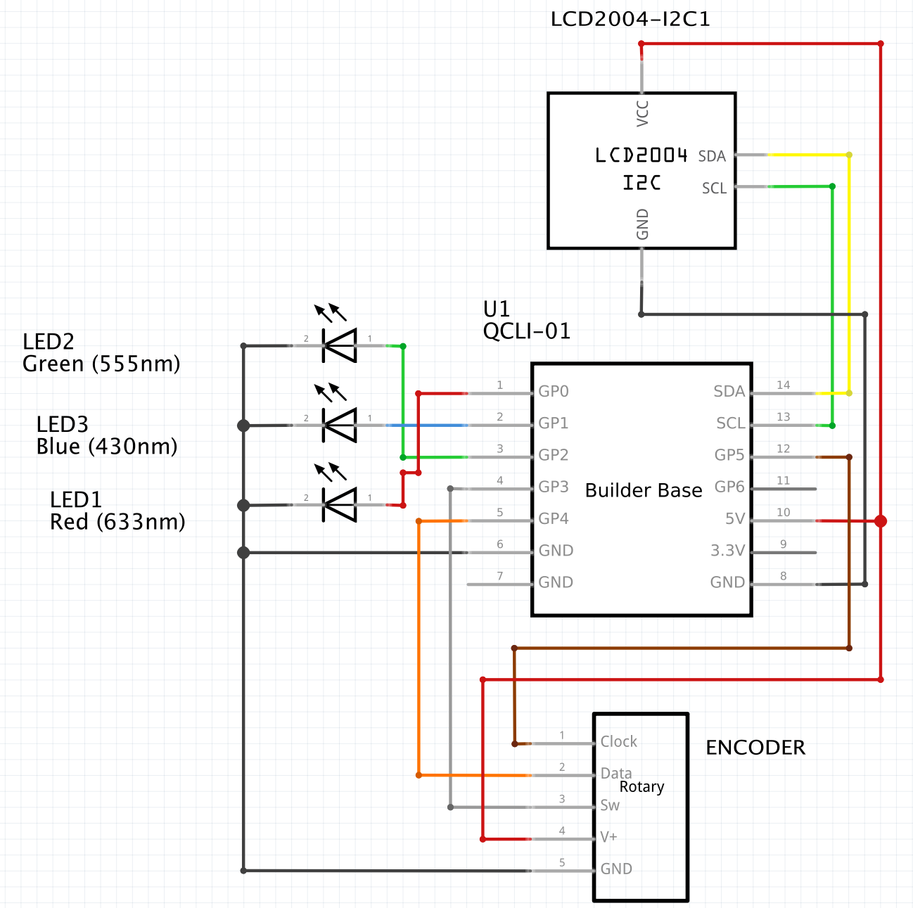
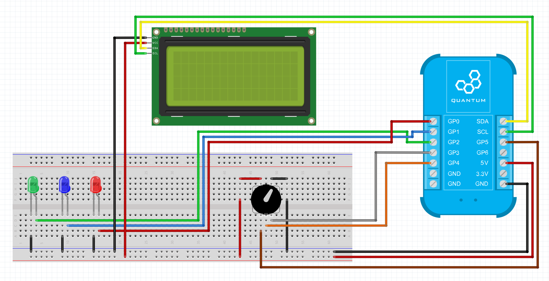
The control unit is where you set the temperature Heat/Cool point.
What you will need to assemble this portion of the project is a Builder Base, an I2C LCD (both 2x16 and 4x16 displays will work), and rotary encoder, and three LEDs (Green, Blue, and Red).
Let’s start by connecting the LCD to the Builder Base.
On the back of your LCD you should have four pins labeled SDA,SCL,VCC, and GND.
You should use MF jumper wires to attach the LCD to the Builder base
.
LCD | Builder Base |
|---|---|
SCL | SCL |
SDA | SDA |
VCC | 5V |
GND | GND |


Now let’s move onto the LEDs (Red,Blue,Green). Each of the GND leads on the LEDs should be attached to the GND port on the Builder Base, and the positive leads should be attached as follows:
You should attach the LEDs to the Builder Base as follows:
LED | Builder Base |
|---|---|
GREEN | GP2 |
BLUE | GP1 |
RED | GP0 |

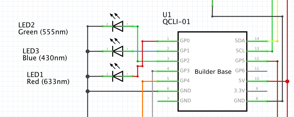
If you followed the above wiring diagram you should now have your LEDs properly connected.
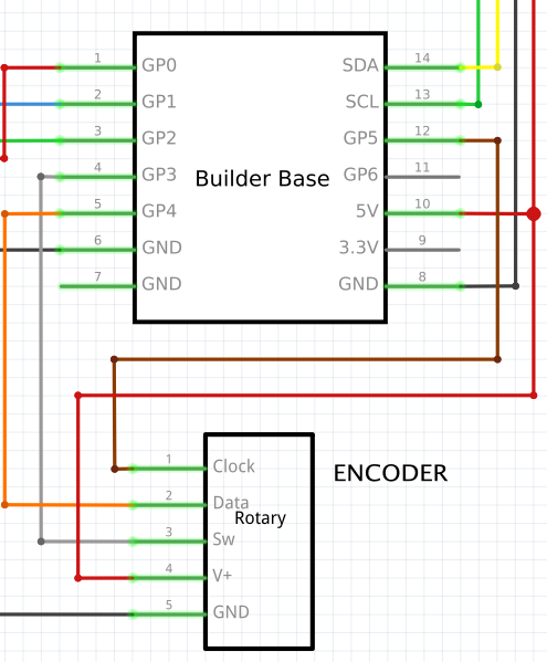
Let’s move onto the rotary encoder. What you will need are 5 MF jumper wires and your rotary encoder.
Rotary Encoder | Builder Base |
|---|---|
Clock | GP5 |
Data | GP4 |
SW | GP3 |
V+ | 5V |
GND | GND |

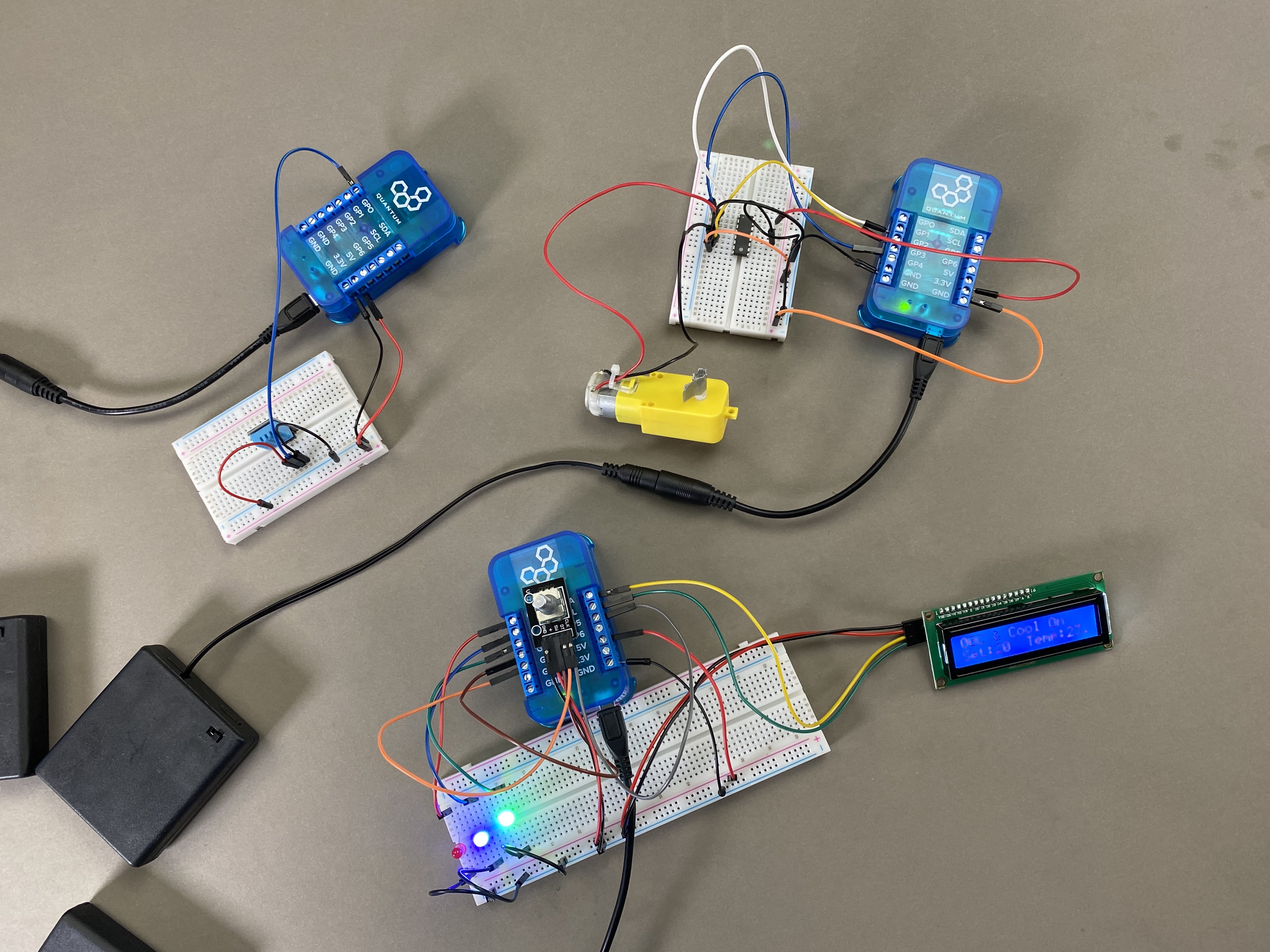
Congratulations! All of the circuits needed for the HVAC system are now complete!
Step 2:Pair the Builder Base
Now we want to pair the Builder Base with our Q-Server. In order to do so, go to the Homescreen of your Q-Server.
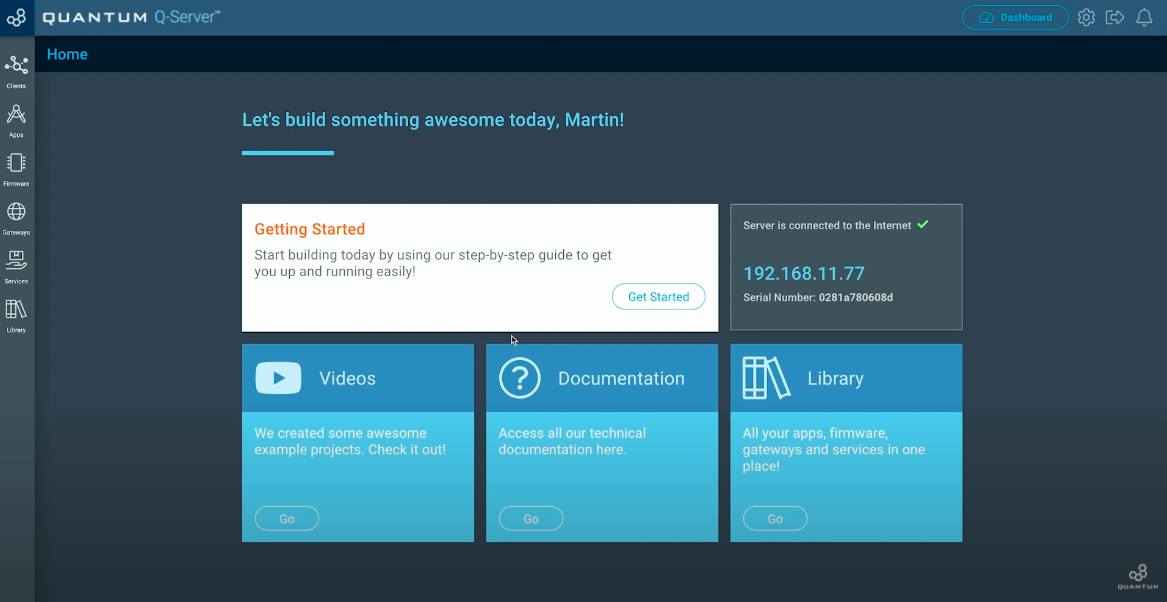
Next click on the lift side symbol labeled “Clients”. Switch to the “Unpaired” tab at the top middle of the screen.
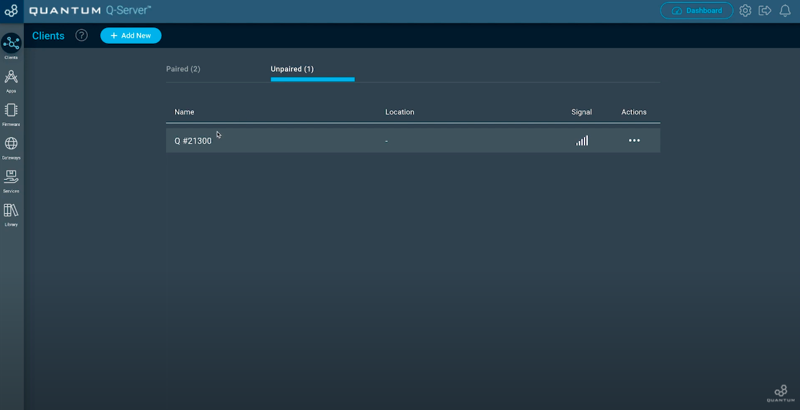
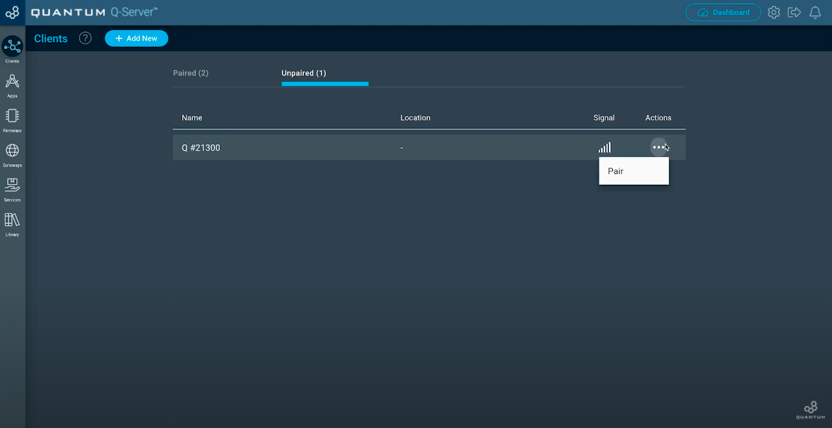
You should see your unpaired Builder Base. If not, check if you have plugged in the power supply for the Builder Base. Now move to the three dots below “Actions” and click “Pair”.
Once your Client is paired, click the “Setup” button.
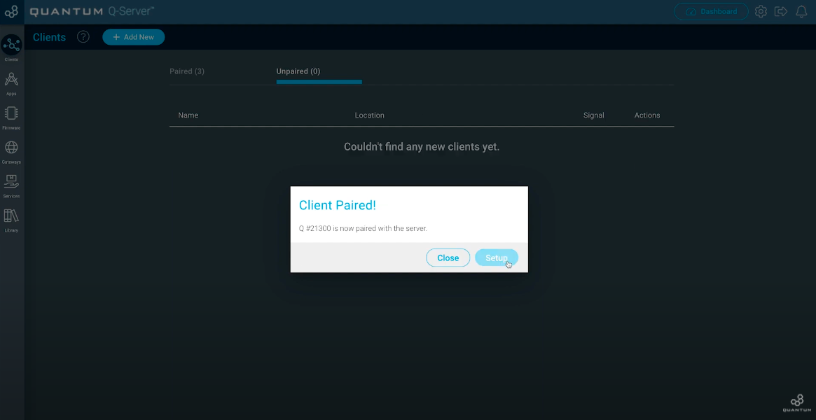
Now you can edit your Client. Give him a Name you want and also a location where you are going to use it. Hit “Save” when you finished.
Build the Firmware
| Tip |
|---|
Remember: All app and firmware files are available in the resources section below! |
Since we use three clients in this project we will need to build three separate firmware files.
Start by navigating to the firmware builder and create a new firmware named “Temperature Probe”.

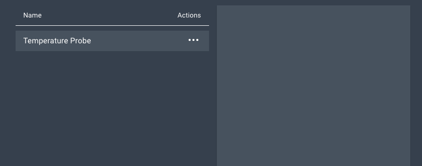
Click on the “+Add Hardware” button and add a Temperature sensor.

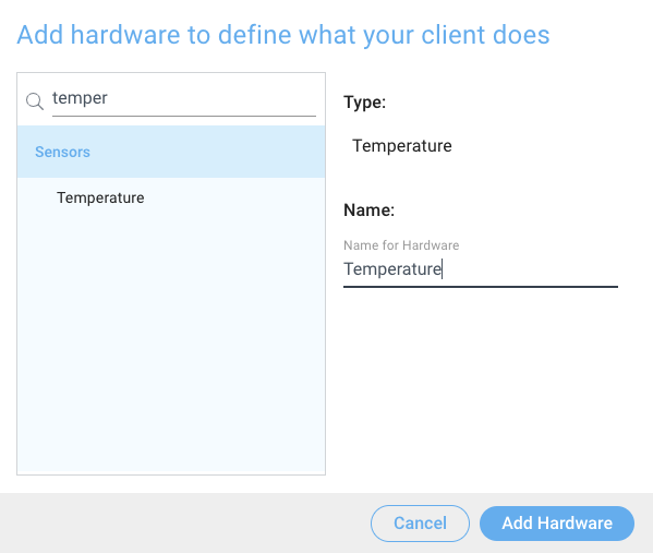
Click the “Add Hardware” button and once the device has been added to your firmware select the DHT11 temperature sensor from the driver drop down menu.
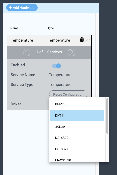

Configure the driver as follows:

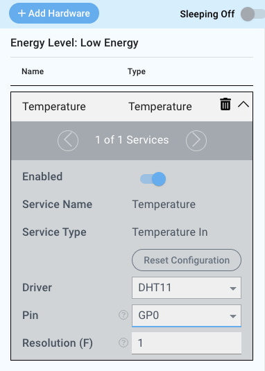
Pin: GP0
Resolution (F): 1
| Info |
|---|
Our system is set to imperial, so the resolution is in ˚F. If you want it to be in ˚C change your measurement units under your system settings. |
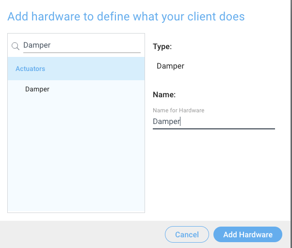
Save this firmware file, and create another named “Damper”.

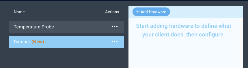
Now, click the “+ Add Hardware” button and add a Damper to your firmware file.

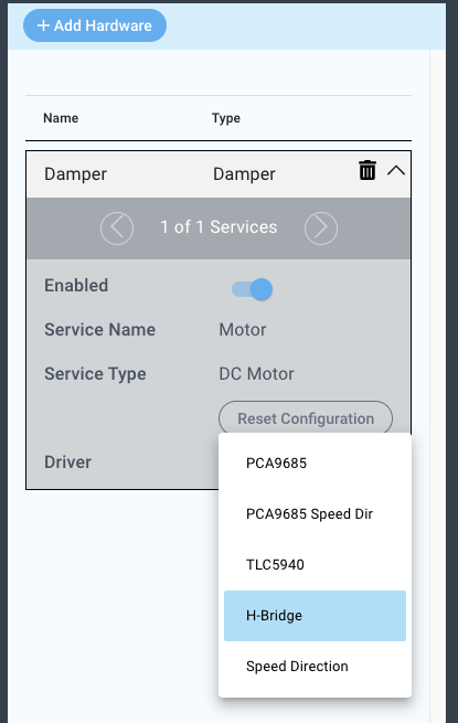
Select the H-bridge from the driver drop down menu.

Configure the driver as follows:
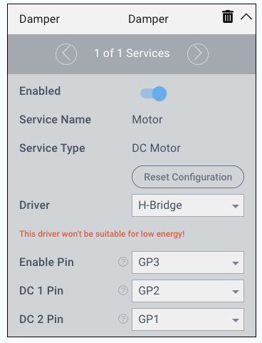

Enable Pin: GP3
DC 1 Pin: GP2
DC 2 Pin: GP1
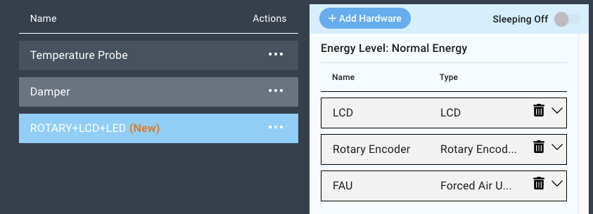
Save your firmware file and add another named “ROTARY+LCD+LED”.

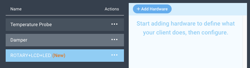
Use the “+Add Hardware” button to add an LCD, a Forced Air Unit, and a Rotary Encoder to your firmware file.

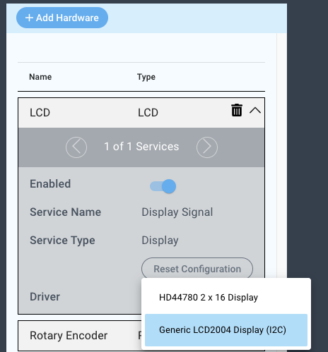
Now let’s configure the LCD. Click on the LCD and select the “Generic LCD2004Display(I2C)” from the driver dropdown menu.

Now we will configure the driver as follows:

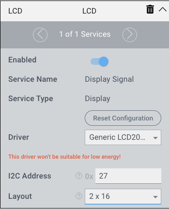
I2C Address: 0x27
Layout: 2x16
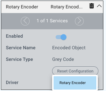
Your LCD device is now configured. We will now configure the rotary encoder.
Select the Rotary Encoder driver from the driver dropdown menu:

Now we will configure the driver as follows:
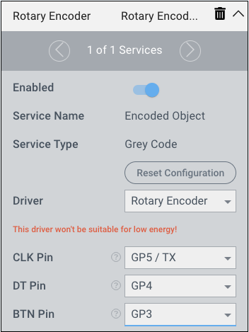

CLK Pin: GP5/TX
DT Pin: GP4
BTN Pin: GP3
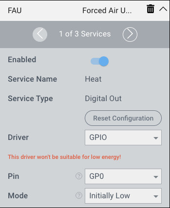
Now let’s configure the FAU.
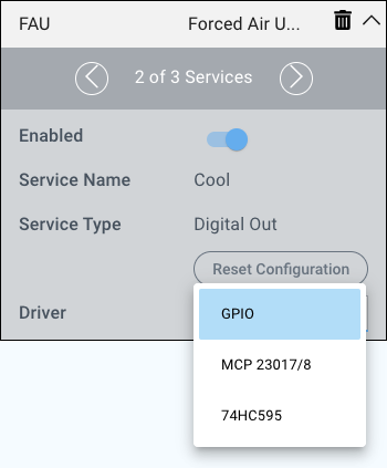
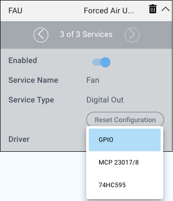
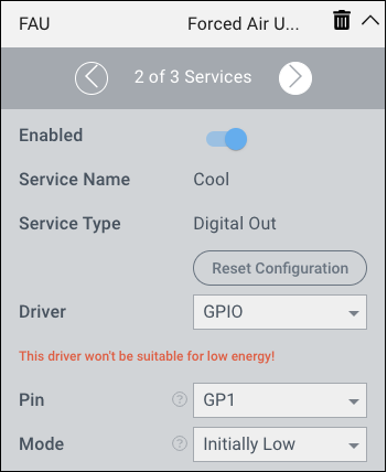
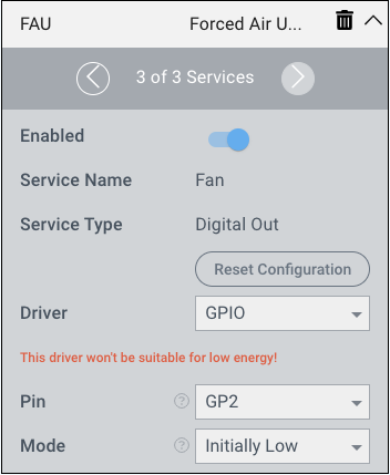
Note that for the FAU there are three services. Each service represents either Heat, Cool, or Fan, and each service has to be configured individually.
Start by selecting the GPIO driver from the driver drop down menu for each service.
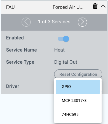


Now we will configure the services as follows:
Heat:

Cool:

Fan:

That’s it, this firmware file is now complete. Save and upload your firmware files to the appropriate clients!
| Info |
|---|
Upload the Damper firmware file to the builder base that the damper is attached to; the temperature probe file to the builder base that the DHT11 is attached to; the Rotary+LCD+LED file that the Control unit is attached to. |
Build the App
| Tip |
|---|
Remember: All app and firmware files are available in the resources section below! |
For this application we will walk you through the basic logic involved. You can follow along and build the application as we describe it, or you can download the application and import it into your applications list. The app and firmware is also available in your Q-Server library.
Here is the HVAC - 1 Zone application:
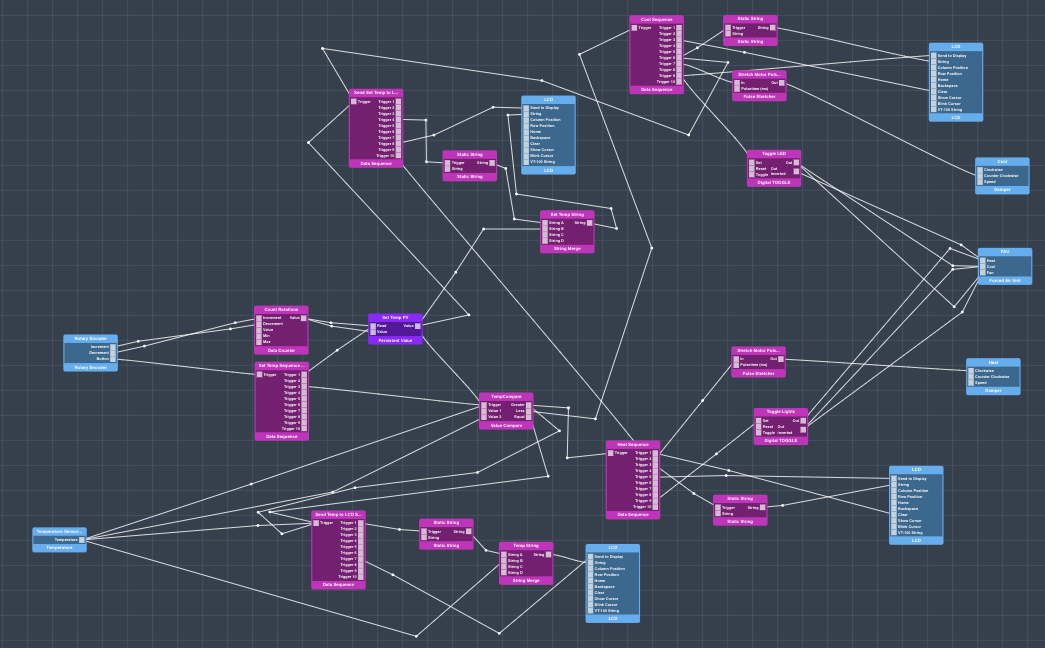
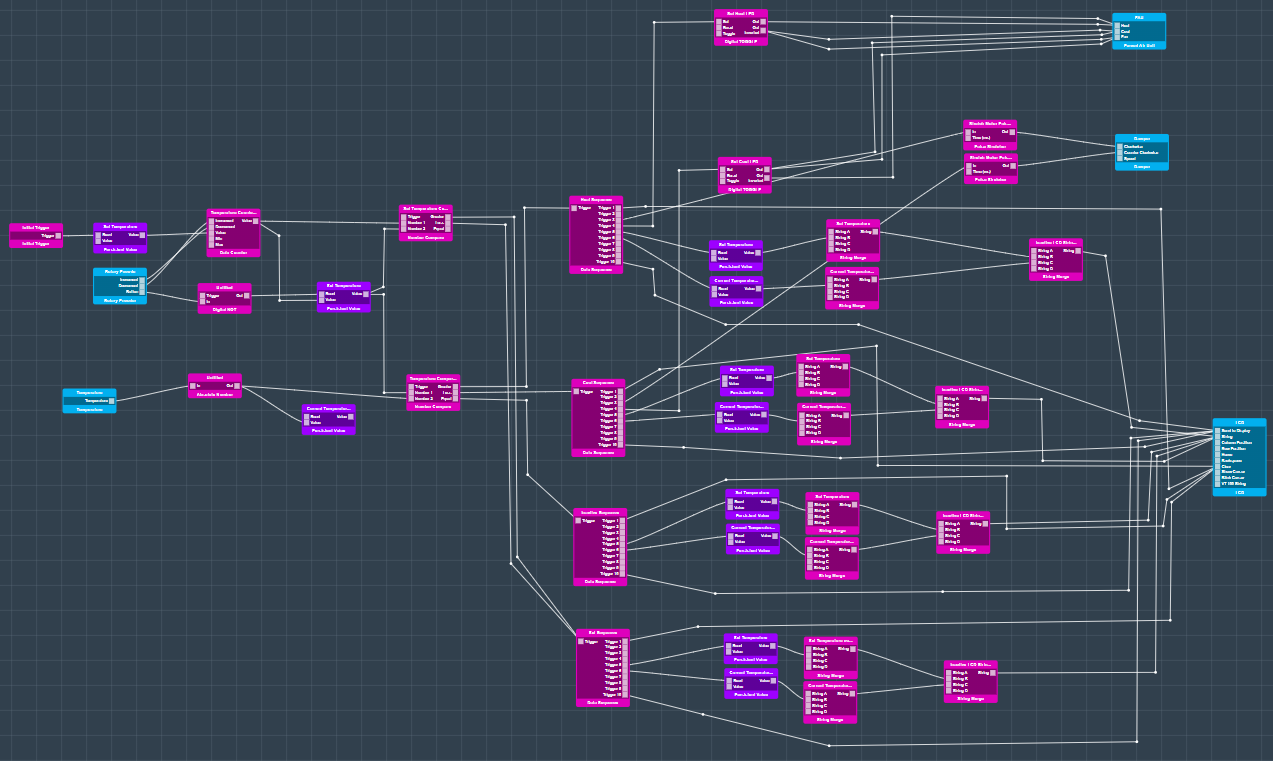
The way it works is you set a temperature point by use of the rotary encoder. If the temperature you set is higher than that of the the current temperature reading, the system switches to a heating mode and If the temperature you set is lower than that of the current temperature reading the Fan and AC turn on. Now that you know the basic function of the app, I will give you a more in depth explanation of the logic involved.
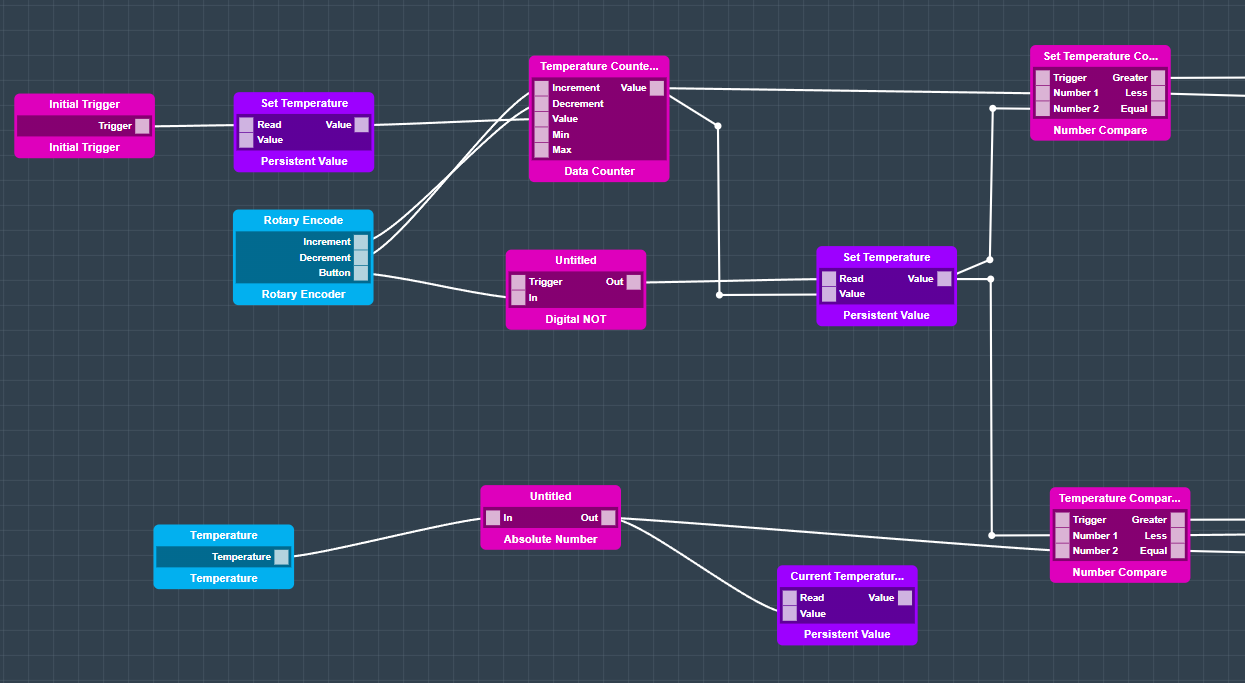
We’ll first start with setting the temperature.
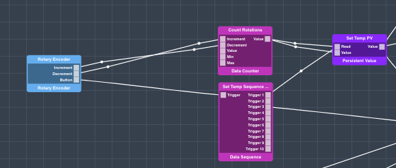
Using the increment and decrement output ports on the rotary encoder with the data counter code block, we are able to count up and down from an initially set value. The default value we have set for the data counter code block is 20. When the rotary encoder is rotated in one direction or another it can increment or decrement from that default value. Every time the value is changed is is output to the “Set Temp PV” persistent value object which stores the value we pass it.
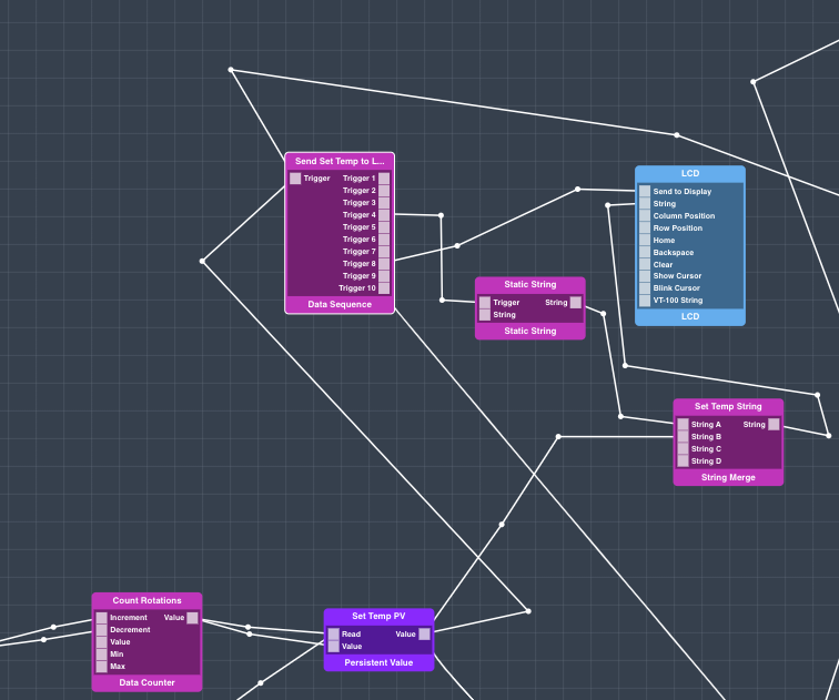
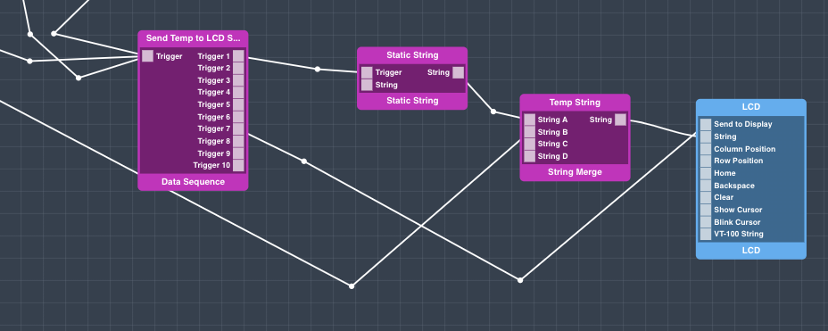
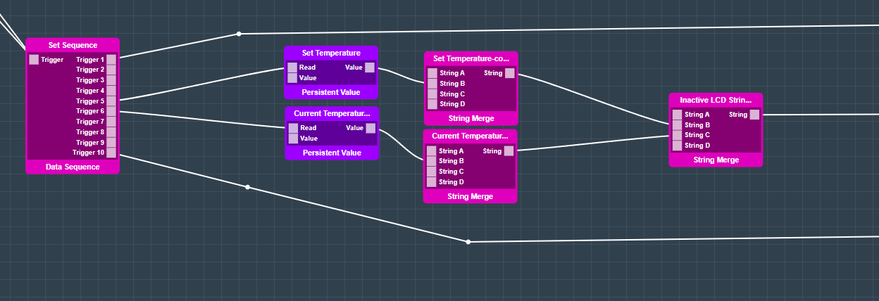
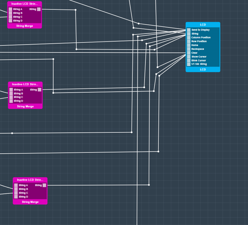
Every time a new temperature is set, the “Send Set Temp to LCD” Data Sequence is triggered. This triggers a static string that reads “Set Temp:” to the “String A” port of the String Merge object. While the new temp value is simultaneously sent to the “String B” port of the same object. The String B port is set to trigger, so when a new value is updated the String Merge block sends the Merged sting “Set Temp: (some temp)” to the “String Port on the LCD”. Once this occurs the Data Sequence sends the new string to be updated on the LCD.
Every time a new temperature reading is sent to the TempCompare object the Send Temp to LCD sequence is triggered. This sequence projects the current temperature readings onto the LCD.
The sequence consists of sending a string that reads “Temp:” to “Port A” of the “Temp String” String Merge object. The temperature readings from the Temperature sensor are sent into the “String B” port of the same object. Once a new temperature is detected, or when the sequence is triggered, the String Merge object sends the new string: “Temp: (new temperature” to the LCD. The data sequence then triggers the Send to Display port on the LCD object and writes the new string to the LCD.
Now we will explore how we determine if the system needs to be set to Cool or Heat.
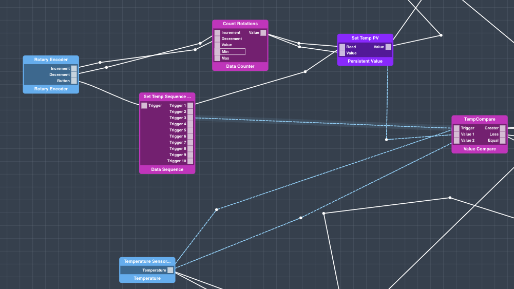
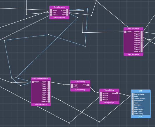
The temperature sensor constantly sends new temperature data to the “TempCompare” Value Compare object. When a new temperature value is sent to the value compare block, or when a new temperature is set the value compare block evaluates wether it should be in the heat or cool modes. If the the “Value 1” (Set Temp) is greater than the “Value 2” (new temperature reading) the system will go into the heating mode, and if the opposite is true the system will go into the cooling mode.
In either event the sequences that are triggered are essentially mirrored.
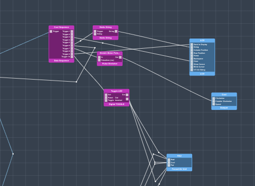
In the Cool sequence a new string that reads “Fan & Cool On” is sent to the string port on the LCD, the LCD is Cleared, and all other sequences involving the LCD are triggered rewrite the relevant information on the Screen. These include the: Send Set Temp to LCD and Send Temp to LCD.
The damper is then set to open by triggering the “Counter Clockwise” port with a pulse stretcher object.
The “Trigger LED” digital toggle is then triggered. This triggers the “Cool” and “Fan” ports on the FAU, and toggles the “Heat” port off. These correspond the the LEDs on the control unit.
Cool sequence:
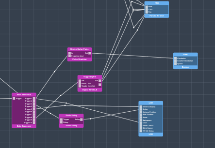
In the Heat sequence a new string that reads “Heat On” is sent to the string port on the LCD, the LCD is Cleared, and all other sequences involving the LCD are triggered rewriting the relevant information on the screen. These include the: Send Set Temp to LCD and Send Temp to LCD sequences.
The damper is then set to close by triggering the “Clockwise” port with a pulse stretcher object.
The “Toggle Lights” digital toggle is then triggered. This triggers the “Heat” port on the FAU, and toggles the “Cool” and “Fan” ports off. These correspond the the LEDs on the control unit.
Heat Sequence:
That’s it for programming the application. Save your app and return to the Applications page.
Step 4: Mapping the ApplicationWe start with a initial trigger to start the application which will be store in a persistent value. The first step is to set the temperature. The rotary encoder interface object will control a data counter object where the temperature can be set. Pressing the button of the rotary encoder object will save the value to the persistent value object. From the persistent value object the value gets send to two number compare objects. One number compare object is connected to a temperature interface object via an absolute number object. The temperature interface object represents the temperature sensor. The number compare object is used to compare the set temperature with the actual temperature from the sensor.
The upper number compare triggers the when the system need a temperature first and was never used before. The “Set Sequence” will be triggered once the system is started for the first time.
When the set temperature is lower than the measured temperature the cool sequence will be triggered because of the number compare code object.
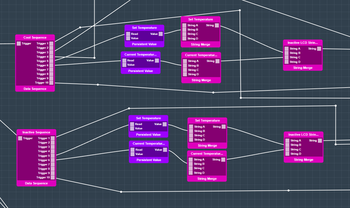
This will trigger the Cool Sequence Data Sequence. The Data Sequence will open the Damper and start the fan and cooling from the Forced Air Unit hardware object. The set temperature and the current temperature will be send to the LCD an be displayed.
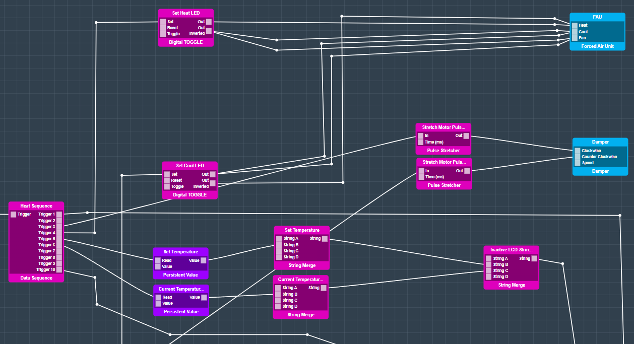
The same sequence is there for a heating progress. If the set temperature is higher than the current temperature, the damper will close and the heating of the FAU will start.
Map the Hardware
You should now be back on the Apps page.
Find your “HVAC - 1 Zone” app and hit the play button.


A list containing all of the devices in your application will expand.
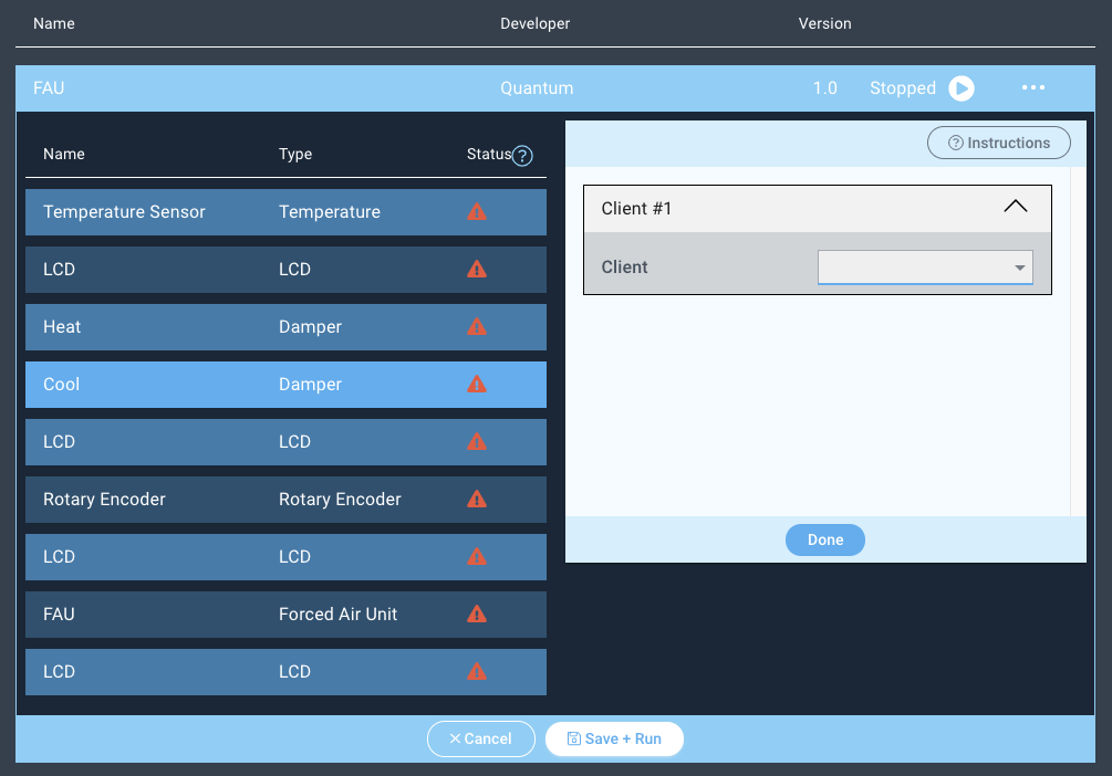

Next click on the “Temperature Sensor” device and the client dropdown menu will appear on the right.
Select the Temperature driver from the dropdown menu and hit “Done”.
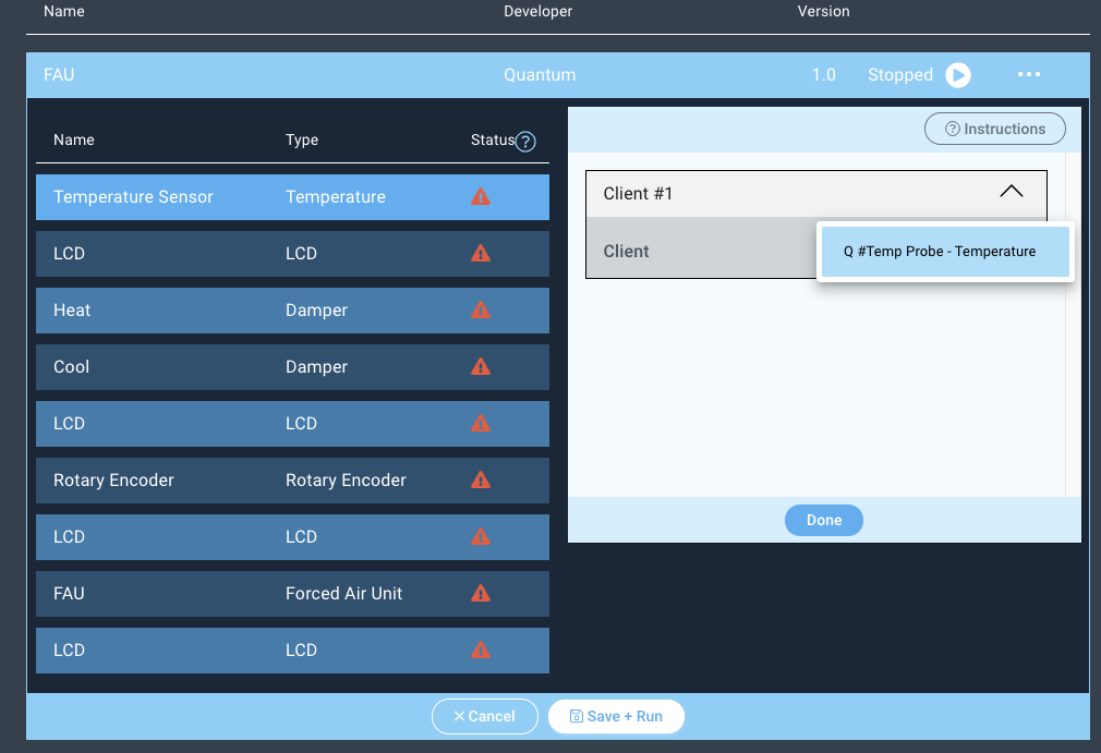

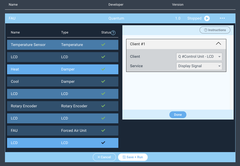
Repeat the same steps for the remaining devices. For this application you should only have one selectable driver per device.
Notice how the status symbols have changed to green checkmarks.

| Info |
|---|
When mapping firmware devices to objects in your Apps it is important to note that only devices and objects of the same type can be mapped together. Using this app for example, we are only given the option to map the client with the button firmware to the button object. |
You are now done mapping your application!
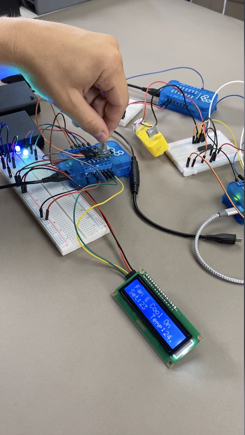
Step 5: Run the Application!
Next, hit “Save + Run”
Run the App!
The application is running now.

Congratulations! Your HVAC project is now complete, have fun!

Schematics

Code
AppResources
Application |
| ||||
|---|---|---|---|---|---|
Firmware |
|
|
Gallery
Resources
App
|
Firmware
|
|
Schematic
Fritzing
Schematics | 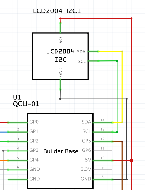  | |||
|---|---|---|---|---|
Diagrams |
|
|
Other Files