| Table of Contents |
|---|
Overview
| Widget Connector | ||||||||||
|---|---|---|---|---|---|---|---|---|---|---|
|
| Info |
|---|
For Fullscreen: https://www.youtube.com/watch?v=SF6G8tAD_o4 |
We feel that no smart home is complete without some form of security system. This is only the prototype of our security system and many revisions will be made to the hardware and software before the design is finalized. Regardless, here’s a peek at what we’ve been working on. The Security System consists of two circuits: one is an access panel that contains a 4x3 Keypad and a 2x16 LCD display, while the second contains a motion sensor, distance sensor, and a buzzer.
|
|
|
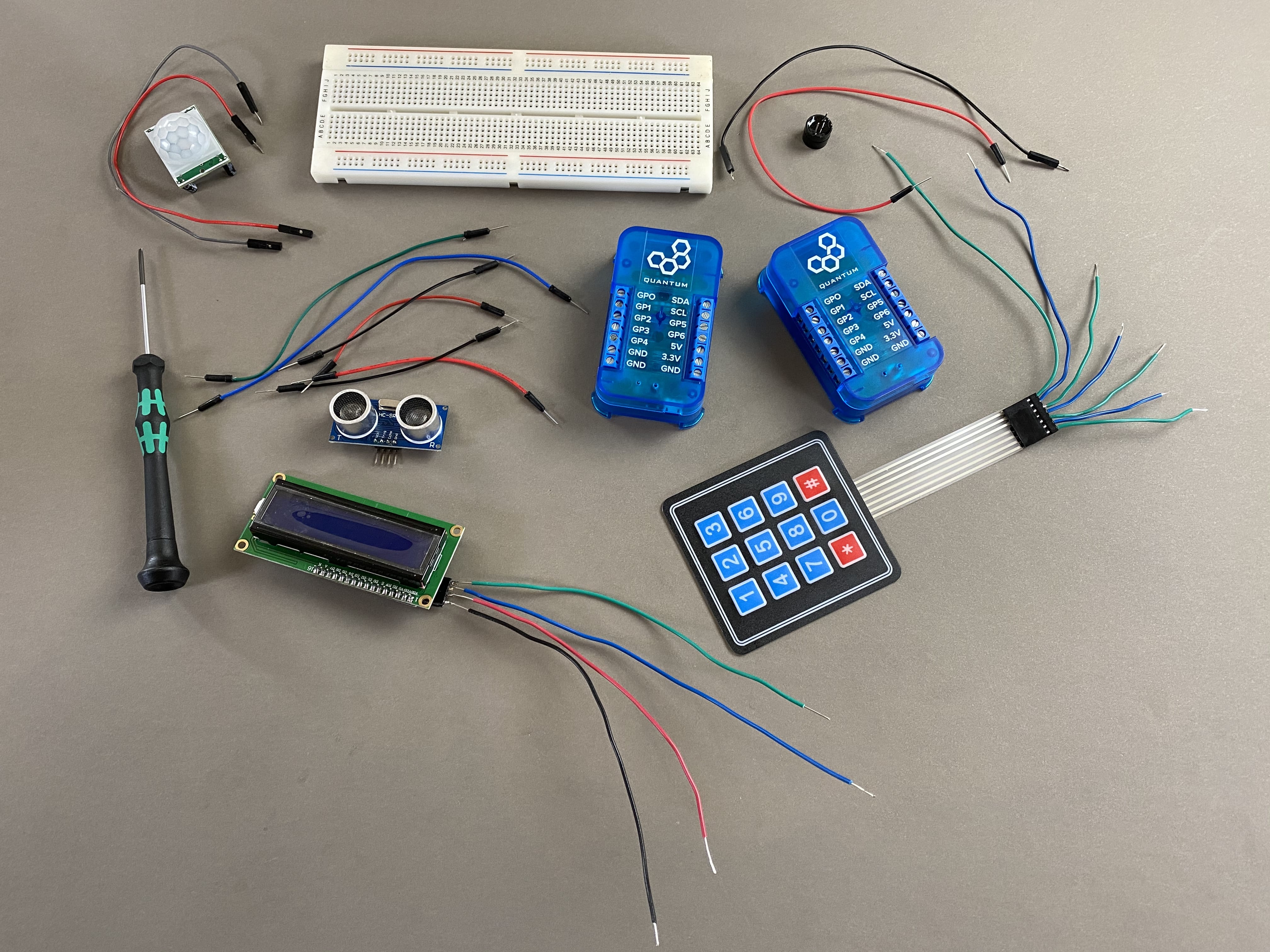
Hardware components
Picture | Name | Quantity | Link |
|---|---|---|---|
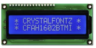 | I2C LCD Display (2x16) | 1 | Included in Component Kit Or you can purchase it here |
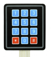 | 4x3 Keypad | 1 | Included in Component Kit Or you can purchase it here |
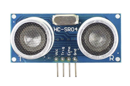 | Ultrasonic Distance Sensor | 1 | Included in Component Kit Or you can purchase it here |
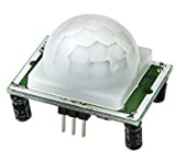 | Motion Sensor | 1 | Included in Component Kit Or you can purchase it here |
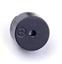 | Buzzer | 1 | Can be purchased here |
 | Breadboards | 1 | Included in Component Kit Or you can purchase it here |
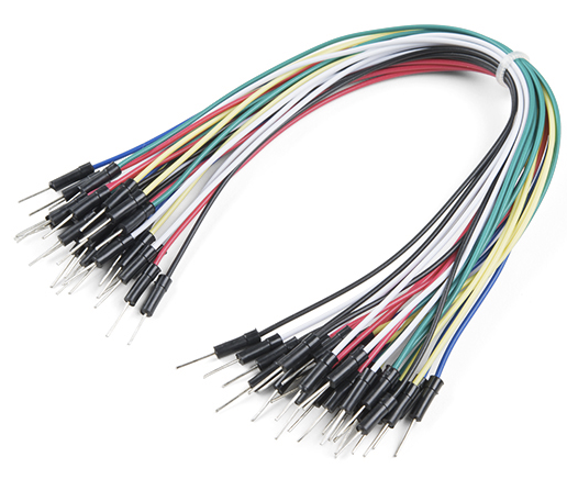 | Male to Male and Male to Female jumper wires | ~20 | Included in Component Kit Or you can purchase it here |
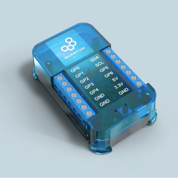 | Q-Client Builder Base | 2 |
Tools Used
Picture | Name | Quantity | Link |
|---|---|---|---|
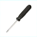 | Small slotted-head screwdriver | 1 | Included in Component Kit Or you can pick from one on our Recommended Tools List |
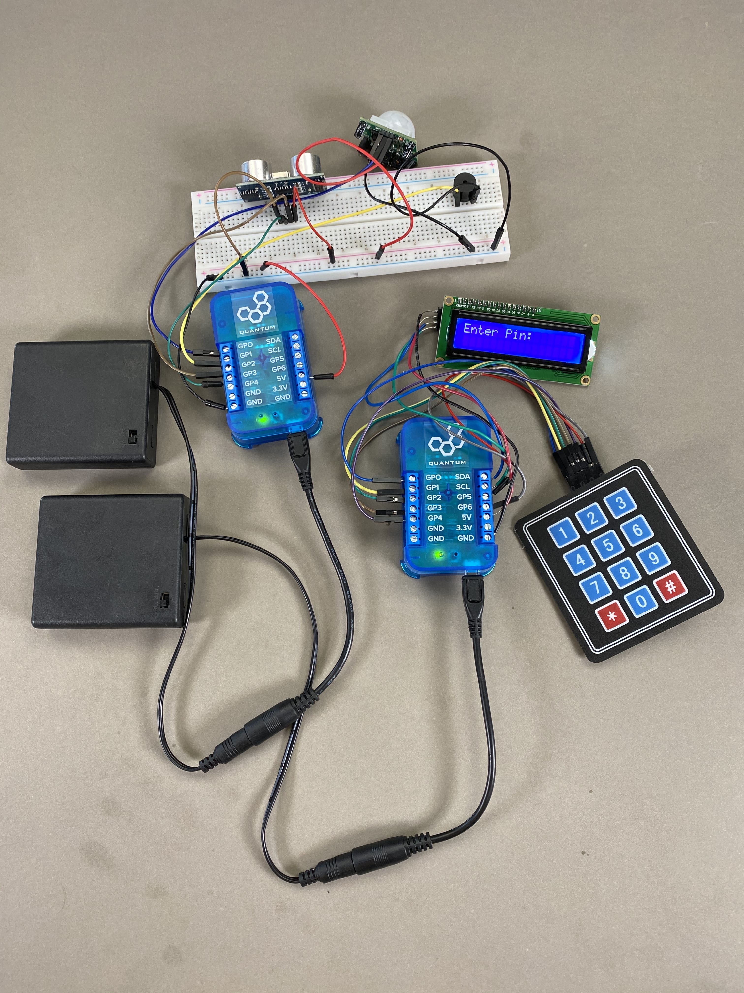
Assemble the Circuit
Start by gathering all of the hardware listed in the parts list above. We will start with the Keypad and LCD circuit and then move onto the Triggers (Motion sensor, distance sensor, and buzzer) circuit.
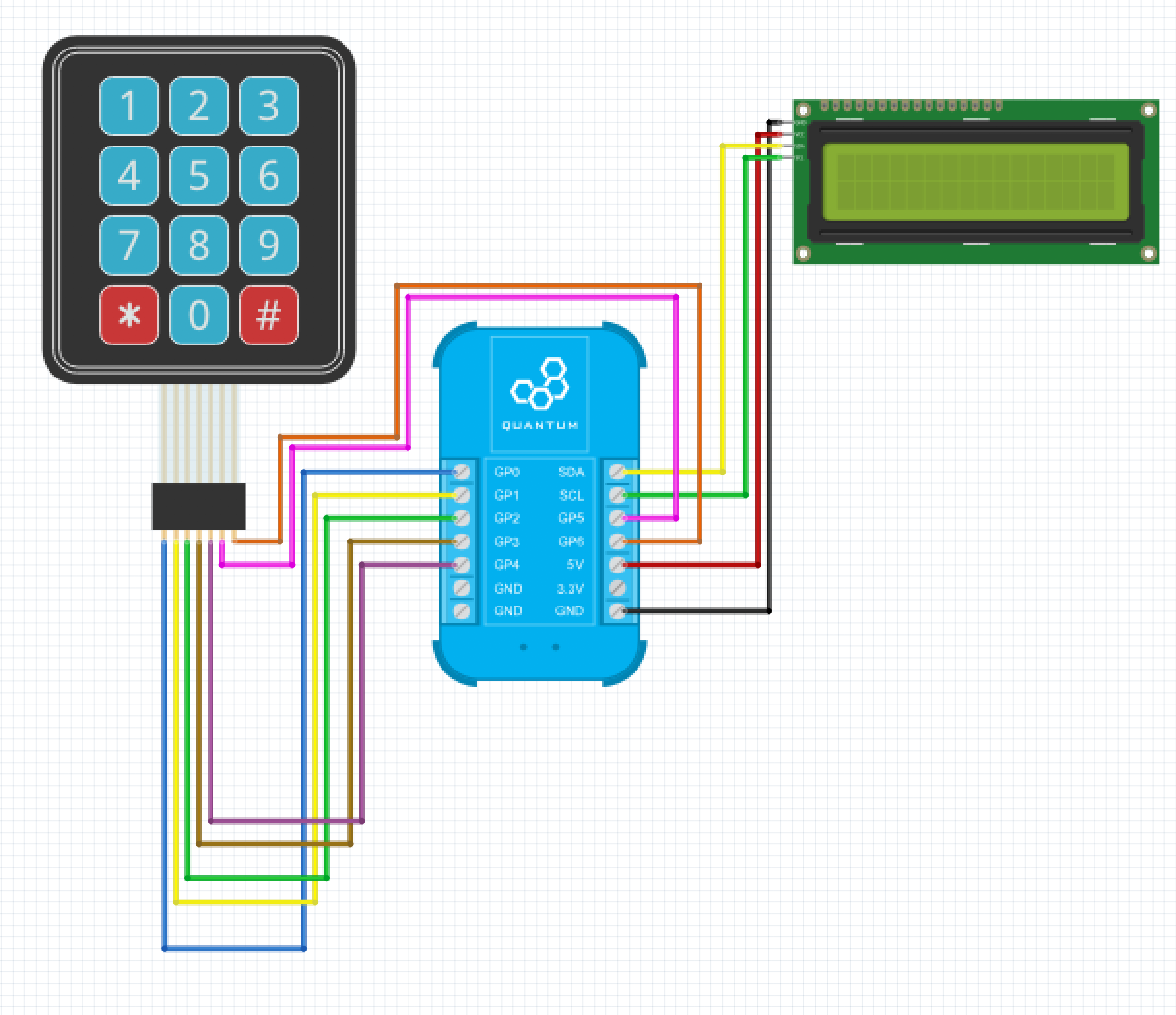
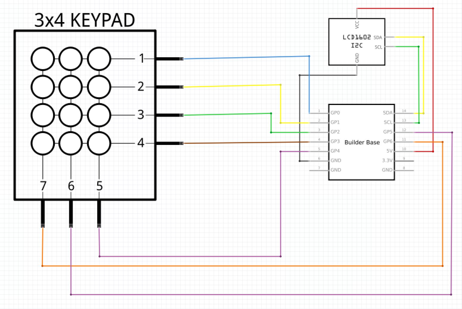
The circuit for the keypad and LCD is very simple. You can use a breadboard to build this circuit, but we found it simpler to attach all components directly to the Builder Base.
Use 7 MM jumper wires and go from left to right to connect the pins from the keypad to the ports on the builder base. So, the left most pin on the keypad is connected to GP0, the second left most to GP1, and so on and so forth.
Now, connect the Vcc and GND terminals on the LCD to the 5V and GND ports on the Builder Base, and then connect the SDA and SCL pins on the LCD to the SDA and SCL ports on the Builder Base.
| Info |
|---|
On the back of the I2C LCD there should be 6 pins. 4 of which are the 5v, GND, SDA, and SCL pins, and the other two are used for brightness. These two pins should come connected together, but if they aren’t you need to connect them. Otherwise, your LCD will not illuminate. |
Use the schematic and breadboard views listed below as a reference.
Now let’s assemble the Triggers circuit. We suggest using a breadboard for this circuit as it makes it easier to power all of the components.
Take your breadboard and attach the GND and Vcc rails to the GND and 5V ports on your Builder Base respectively.
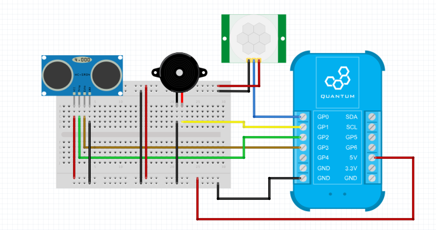

Now, let’s wire the motion sensor. Connect the VCC and GND pins to the 5V and GND rails on the breadboard. Wire the Data pin to the Builder Base as follows:
Motion Sensor | Builder Base |
|---|---|
Data | GP0 |
Now, we will wire the buzzer. Connect the GND pin on the Buzzer to the GND rail on the breadboard, and wire the positive pin to the Builder Base as follows:
Buzzer | Builder Base |
|---|---|
| GP1 |
Lastly, we will wire up the distance sensor. Again, connect the Vcc and GND pins on the distance sensor to the 5v and GND rails on the breadboard. Now wire the Echo and Trigger pins to the builder Base as follows:
Distance Sensor | Builder Base |
|---|---|
Trigger | GP2 |
Echo | GP3 |
Congratulations! All of the circuits needed for the Security system are now complete!
Build the Firmware
| Tip |
|---|
Remember: All app and firmware files are available in the resources section below! |
Since we use two Builder Bases in this project we will need to build two separate firmware files.
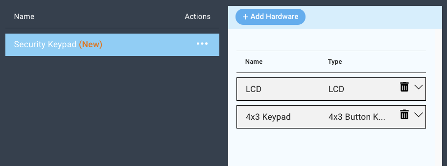
Start by navigating to the firmware builder and create a new firmware named “Security Keypad”.

Click on the “+Add Hardware” button and add a LCD and a 4x3 Keypad.
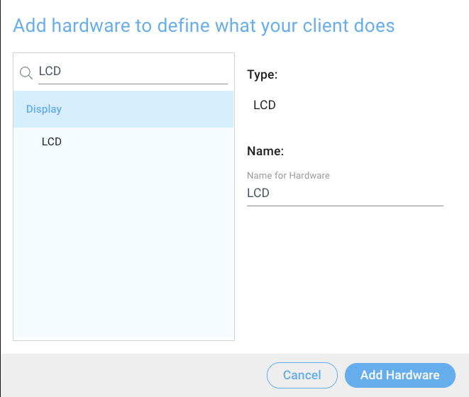

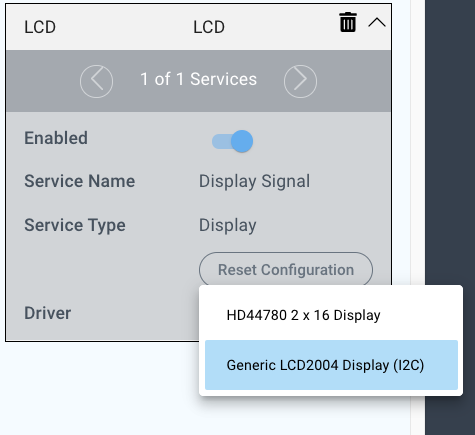
Now, click on the LCD device and select the “Generic LCD2004 Display (I2C)” driver from the driver drop down menu.
Configure the driver as follows:
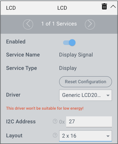
I2C Address: 0x27
Layout: 2x16
Now, we will configure the 4x3 Keypad. You will notice the the 4x3 Keypad has 12 services to configure. You can cycle through these by clicking on the left and right arrows.
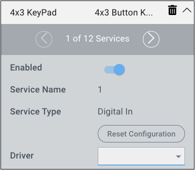
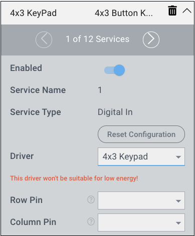
For each service you will have to select the Driver, and the row/column pin for the service. Each service corresponds to a button on the keypad. Follow the table below to configure all 12 services.
Service | Driver | Row Pin | Column Pin |
|---|---|---|---|
1 | 4x3 Keypad | GP0 | GP4 |
2 | 4x3 Keypad | GP0 | GP5/Tx |
3 | 4x3 Keypad | GP0 | GP6/Rx |
4 | 4x3 Keypad | GP1 | GP4 |
5 | 4x3 Keypad | GP1 | GP5/Tx |
6 | 4x3 Keypad | GP1 | GP6/Rx |
7 | 4x3 Keypad | GP2 | GP4 |
8 | 4x3 Keypad | GP2 | GP5/Tx |
9 | 4x3 Keypad | GP2 | GP6/Rx |
0 | 4x3 Keypad | GP3 | GP4 |
* | 4x3 Keypad | GP3 | GP5/Tx |
# | 4x3 Keypad | GP3 | GP6/Rx |
When you have all services configured save your firmware!
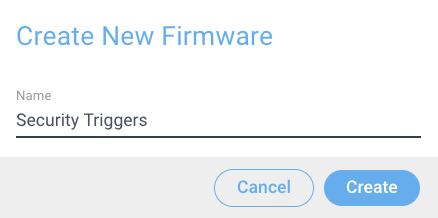
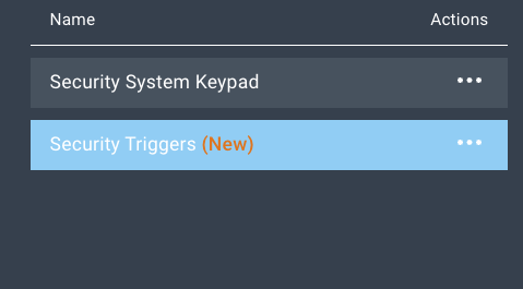
Now, create another firmware file named “Security Triggers”.
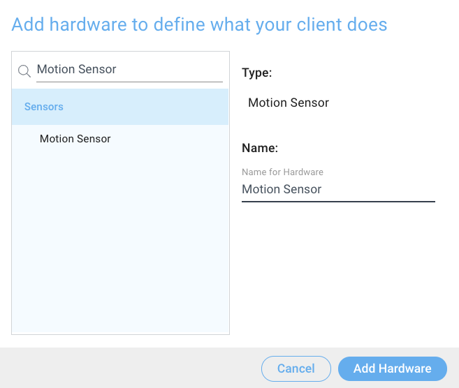
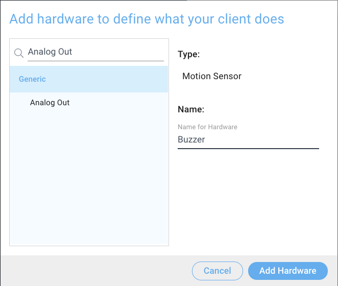
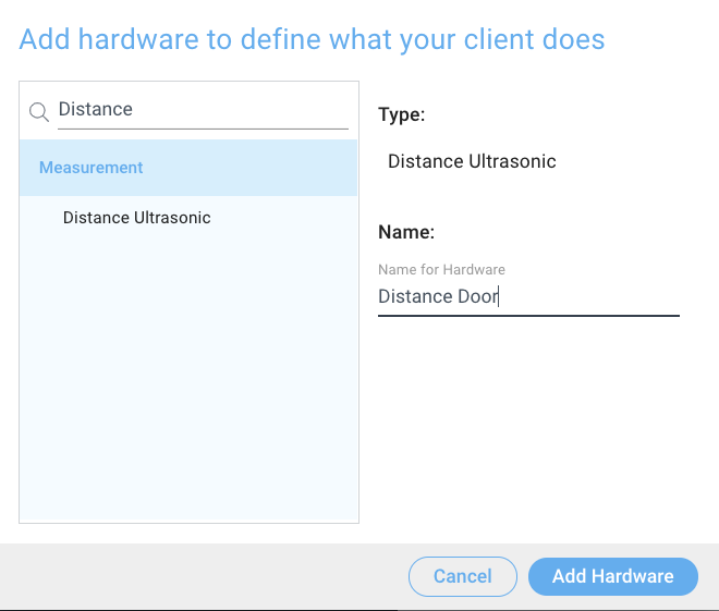
Now, click the “+ Add Hardware” button and add a Motion Sensor, a Distance Sensor, and an Analog Out devices to your file. Name them as we do.
For the Motion sensor, select the HC-SR501 driver from the driver dropdown menu.
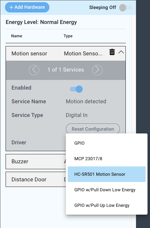
Configure the driver as follows:
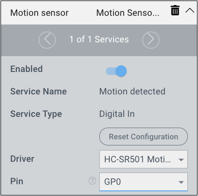
Pin: GP0
Now we will configure the Buzzer. Select the “GPIO” Driver from the driver dropdown menu.
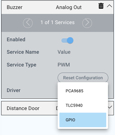
Now we will configure the driver as follows:
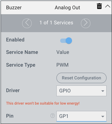
Pin: GP1
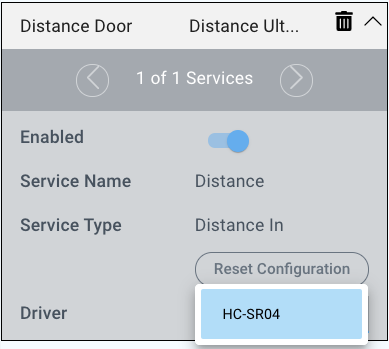
Now, we will configure the Distance Sensor.
Select the HC-SR04 driver from the driver dropdown menu
Now we will configure the driver as follows:
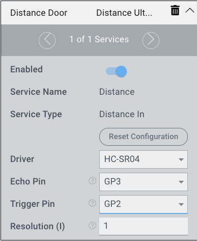
Echo Pin: GP3
Trigger Pin: GP2
Resolution(I): 1
| Info |
|---|
Our system is set to imperial in the settings. If yours is set to metric you will likely want to change your resolution value. |
That’s it, your firmware files for the Security System are now complete. Save and upload your firmware files. The Security Keypad firmware should be uploaded to the Builder Base that the Keypad and LCD are connected to, and the Security Triggers firmware should be uploaded to the Builder Base that the Sensors and Buzzer are connected to.
Build the App
| Tip |
|---|
Remember: All app and firmware files are available in the resources section below! |
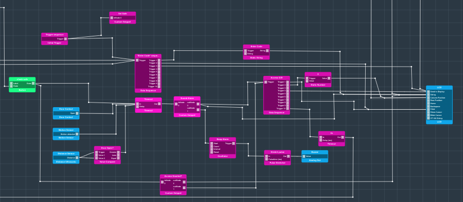
For this application we will walk you through the basic logic involved. You can follow along and build the application as we describe it, or you can download the application and import it into your applications list.
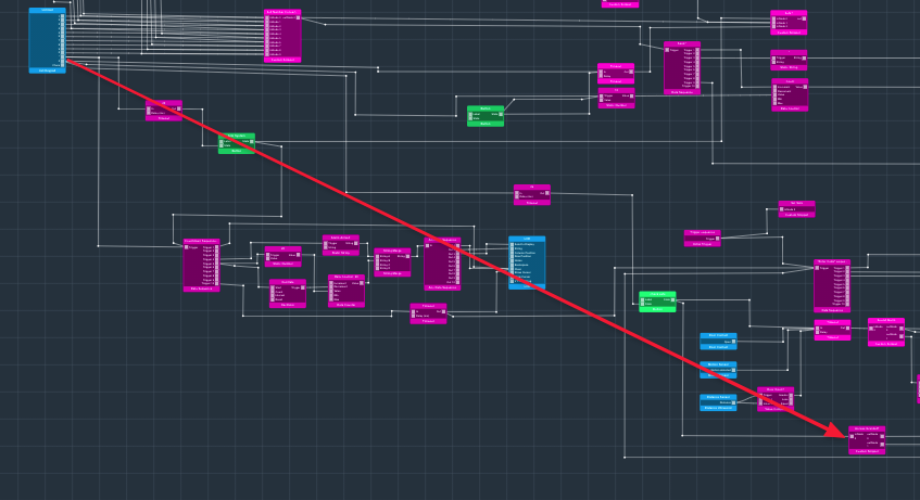
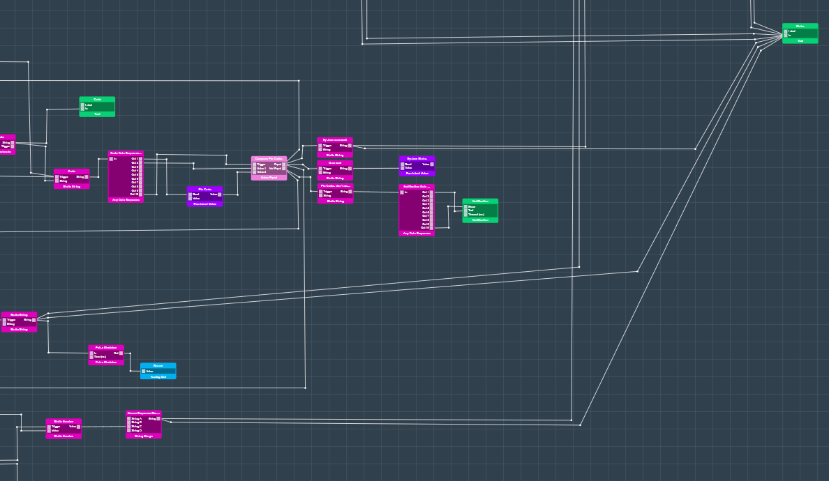
Here is the Security System application:
| Warning |
|---|
Please note that this security system application is in a highly prototypical state and does not function flawlessly. We will be updating this application in the coming months to work more effectively. |
In this description we will break the Application up into four main parts: 1. Code Set, 2. Code Input/Evaluation, 3. Sensor Input, and 4. Arm Alarm Countdown
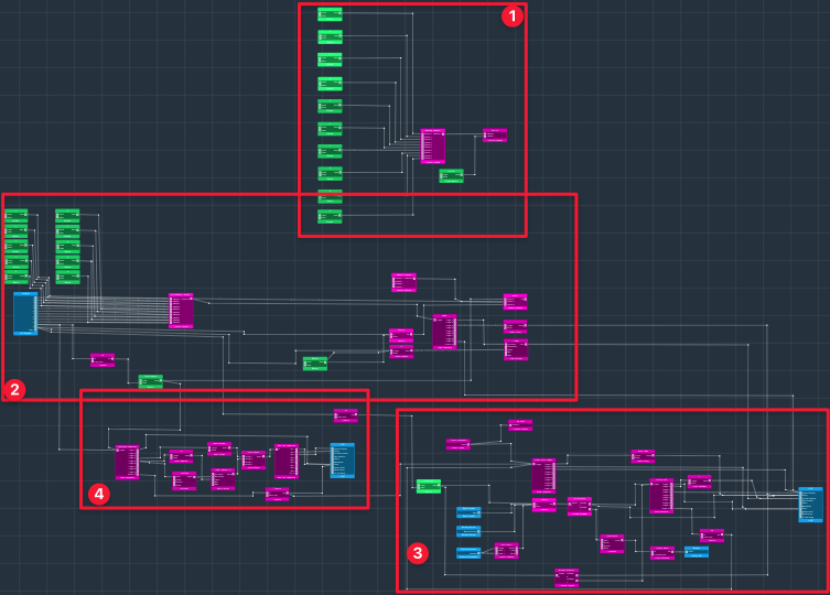
In its current state, when the app is started you need to set the pin code via the dashboard interface. This occurs here in the Code Set portion of the app.
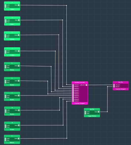
The pin is set using two custom code blocks. One converts a dashboard button press to a number and the other stores the number in a global conext array.
Number Convert:
| Code Block |
|---|
if(trigger === 9){
  return[0, new Date()]
}
else{
return [trigger+1, new Date()]
} |
Set Pin:
| Code Block |
|---|
let val1 = parseFloat(inPorts[0].value);
let val2 = parseFloat(inPorts[1].value);


if(context.j === undefined){
 globalContext.test = [];

 context.flag = 0;
 context.j = 0;
}


switch(trigger){

case 0:{
  if(context.flag === 1){
    globalContext.test[context.j] = val1;
 context.j++;
}

};break;

case 1:{
    if(context.flag === 0){
      context.flag = 1;
      globalContext.test = [];
      context.j=0;
    } else{
      if(context.flag === 1){
        context.flag = 0;
      }
    }


};
;break;
} |
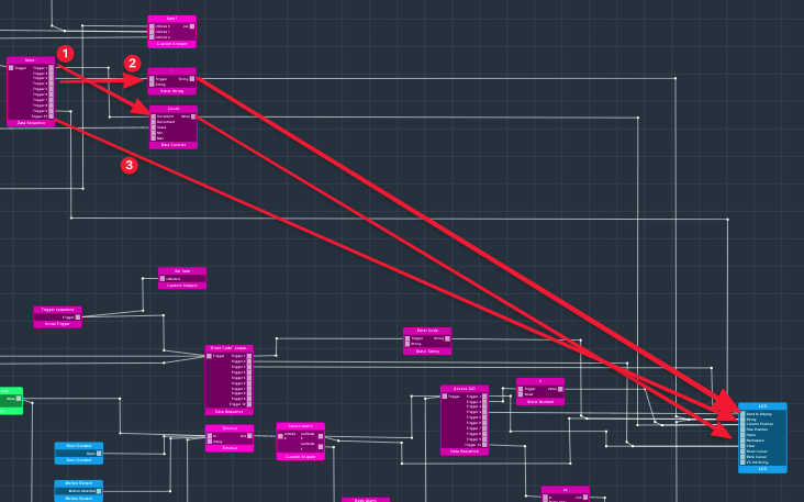
Now we will take a look at the code input/evaluation section of the program.
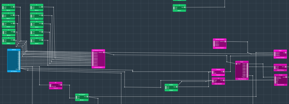
Here we have a 4x3 Keypad object connected to another number convert custom snippet. This takes the digital output from the 4x3 keypad object and depending on the port it is received in converts it into a number. This number convert custom snippet is identical to the one used above.
This number is then passed into a custom snippet named “Safe?”.
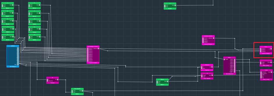
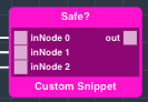
The “Safe?” snippet takes inputs from three ports. The first port “InNode0” serves as a way to arm the system. We arm the system via used of the “*” key on the keypad If a trigger is received from this port, this code executes:
| Code Block |
|---|
case 0:{
globalContext.safe = 0;

};break; |
The second port “inNode1” takes in numbers from the number convert custom snippet and stores them in an enter array. When a value is received through this port, this code executes:
| Code Block |
|---|
case 1:{

    context.entr[context.i] = val2;
    context.i++;
|
And lastly, the third port serves as the trigger for code evaluation. The third port is connected to the “#” key on the 4x3 Keypad object. When the”#” key is pressed it acts as the enter button. You can see the code here:
| Code Block |
|---|
 if(globalContext.test.length != context.entr.length){
    globalContext.safe = 0;
     context.entr = [];
      context.j=0;
      context.i=0;
    return[globalContext.safe];
  }

  else{
    for(var p = 0; p <  globalContext.test.length; p++){
     if(globalContext.test[p] != context.entr[p]){
      globalContext.safe = 0;
      context.entr = [];
      context.j=0;
      context.i=0;
      return[globalContext.safe];}


    }
     globalContext.safe = 1;
      context.entr = [];
      context.j=0;
      context.i=0;
    return[globalContext.safe];
} |
Here is the complete code for the “Safe?” custom snippet:
| Code Block |
|---|
let val1 = parseFloat(inPorts[0].value);
let val2 = parseFloat(inPorts[1].value);


if(context.i === undefined){

 context.entr = [];
 context.i = 0;
 context.j = 0;
 globalContext.safe = 1;


}


switch(trigger){

case 0:{
globalContext.safe = 0;

};break;

case 1:{

    context.entr[context.i] = val2;
    context.i++;


};break;

case 2:{
  if(globalContext.test.length != context.entr.length){
    globalContext.safe = 0;
     context.entr = [];
      context.j=0;
      context.i=0;
    return[globalContext.safe];
  }

  else{
    for(var p = 0; p <  globalContext.test.length; p++){
     if(globalContext.test[p] != context.entr[p]){
      globalContext.safe = 0;
      context.entr = [];
      context.j=0;
      context.i=0;
      return[globalContext.safe];}


    }
     globalContext.safe = 1;
      context.entr = [];
      context.j=0;
      context.i=0;
    return[globalContext.safe];
  }

};break;

} |
This section of the program also sends a “*” to the LCD every time one of the numbers on the 4x3 Keypad is depressed. With every number depressed the “Send *” Data sequence is triggered this then increments a count by one that ranges from [10 → 16]. This count corresponds to the column position on the LCD, so that every time a new number is input a new “*” is input after the last. Also, every time the “#” key is depressed this count is reset. Anyways, this number is sent to the column position port on the LCD object.
The data sequence then triggers the static string block that contains “*”, and sends it to the string port on the LCD.
Lastly, the data sequence triggers the “Send to Display” port on the LCD, actually making the new message appear on the LCD.
We will now take a look at the Sensor Input portion of the program.
We have an initial trigger connected to a custom snippet named “Set Safe”. When the app is initially started, the system is set to the safe position so that the alarm doesn’t instantly trigger.
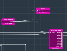
Here is the code:
| Code Block |
|---|
globalContext.safe = 1; |
The initial trigger also triggers the “Enter Code” Data Sequence. This data sequence triggers a Static String of “Enter Code:” and sends it to the LCD hardware object.
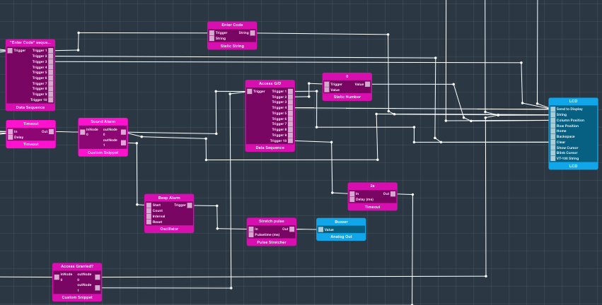
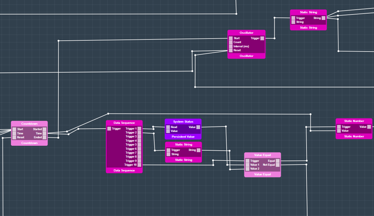
We will now take a look at how all of the sensors are used as triggers for the alarm.
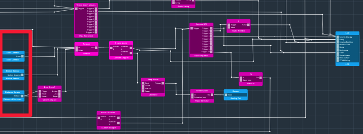
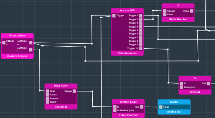
All three sensors, the door contact, Motion Sensor, and Distance Sensor, lead into a 2s timeout object. This timeout object then leads into a custom code snippet named Sound Alarm.
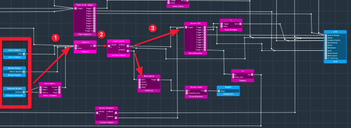
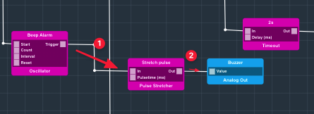
This custom snippet checks to see if the globalContext.safe variable is set to a 0 or a 1. If it is a 1 the system is safe and nothing happens. However, if the variable is set to 0 the string “Intruder Alert” is sent to the “Access G/D Data Sequence via the port “outNode0”, and a trigger is sent the the “Beep Alarm” Oscillator object via the second port “outNode1”.
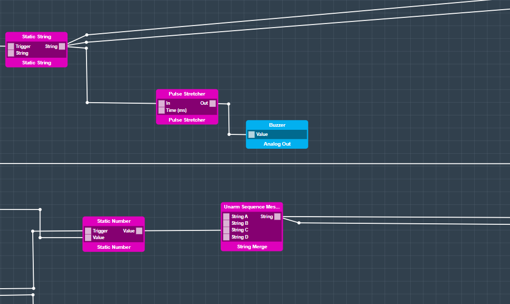
The “Stretch Pulse” Pulse Stretcher is then triggered which in turn activates the buzzer.
If we are entering a code and trying to disarm the system this route from the “#” key on the 4x3 keypad is taken.
From the 4x3 Keypad the “Access Granted?” custom snippet is triggered, and if the globalContext.safe variable is set to 1, the string “Access Granted” will be passed to the LCD, and the “Access G/D” data sequence will be triggered.
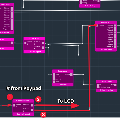
Here is the code for the “Access Granted” custom snippet:
| Code Block |
|---|
if(globalContext.safe ===1){
  return["Access Granted",new Date()];
} |
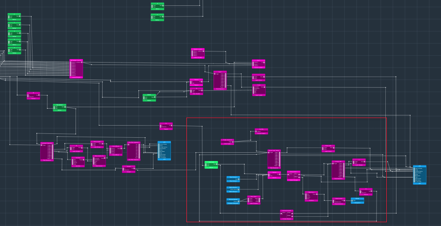
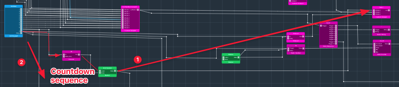
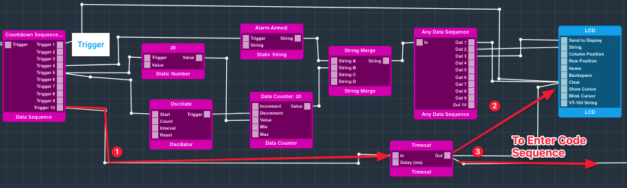
Lastly, we will take a look at the Arm Alarm Countdown portion of the app.
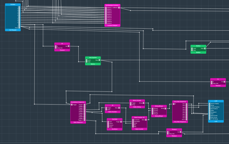
When the “*” key is depressed on the 4x3 Keypad the “Countdown Sequence” object, and a 20 second timeout are triggered. These execute simultaneously. After the 20 second timeout is up, the system will be armed as the “inNode0” on the “safe?” block that we discussed earlier will be triggered.
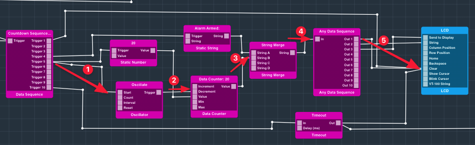
The countdown sequence object handles the 20 second count down that appears on the LCD screen. First, the LCD is cleared, and then the String “Alarm Armed:” is sent to the “String Merge” object.
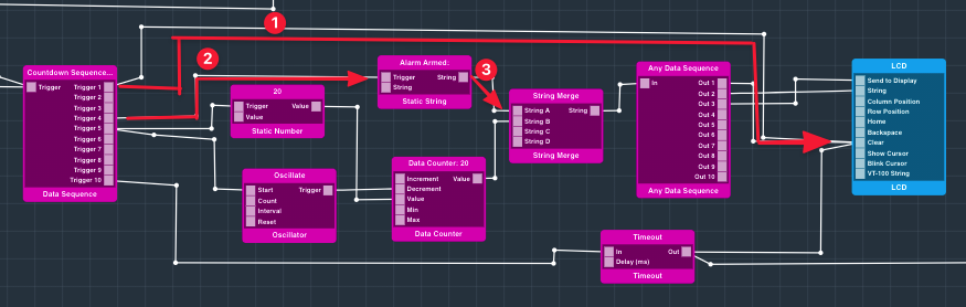
Next, the number 20 is sent to the value port on the data counter object. This value is then passed to the “String B” port on the Data Counter. The conjoined string of “Alarm Armed:” + “20” is then sent through the any data sequence to the LCD.
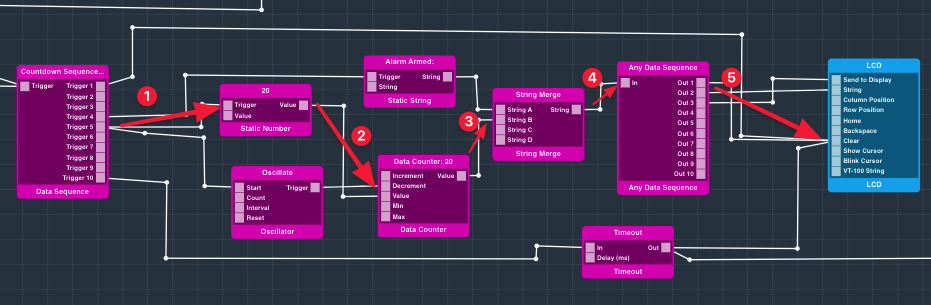
The Oscillate code block is then triggered with the count set to 20 and the interval to 1000ms.
This then triggers the Data counter 20 times, decrementing the counter once per second until the count of 0 is reached. Every time the count is decremented, a new value is sent to the String Merge object, which then passes the new merged string to the “Any Data Sequence”, which finally passes the new string “Alarm Armed:” + “(some new count)” to the LCD.
Finally, the timeout block that has been running concurrently finishes its timeout and triggers the “Clear” port on the LCD and the “Enter Code:” sequence. This leaves the system in its armed state ready for a code to be entered to disarm it.
 That’s it for programming the application. Save your app and return to the Applications page
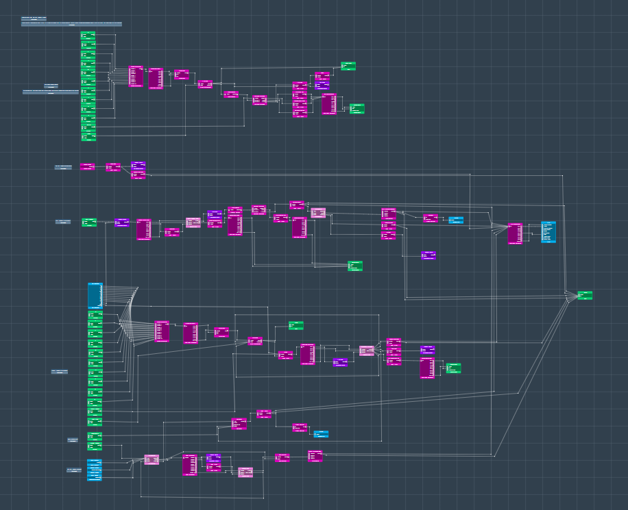
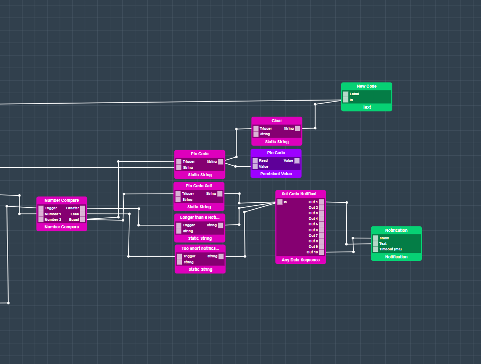
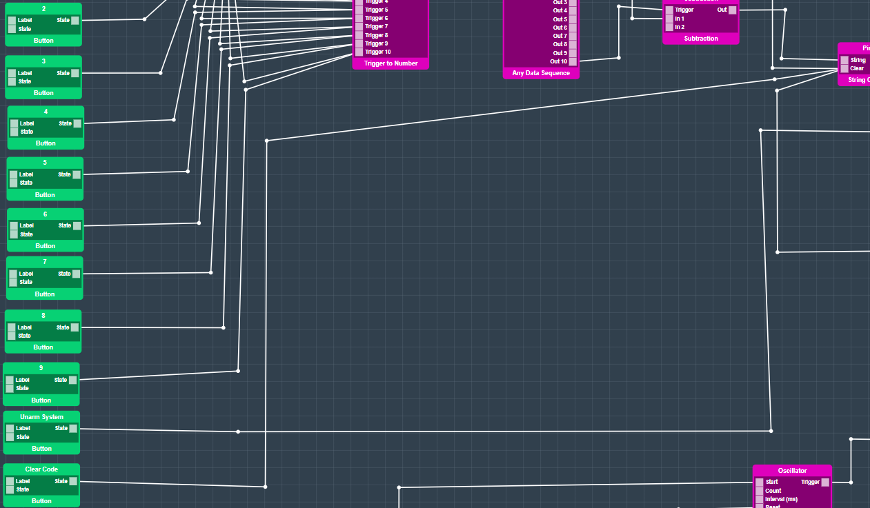
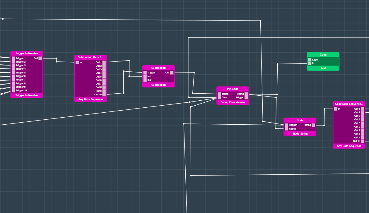
As you can see there are multiple comments for the application and each section of it to let you know which object section is responsible for a certain action or function of the system. Let’s look at the first section at the top. This section is used to configure your system. All button interface objects are connected to a trigger to number object. The data will then be processed to a String Concatenate. Concatenation is the process of appending one string to the end of another string.
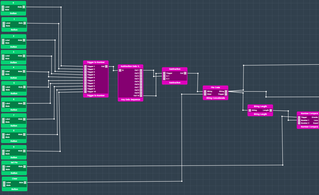
The entered pin code will then be compared because it needs to have 6 digits. The pin code then will be saved in a persistent value object and also displayed.
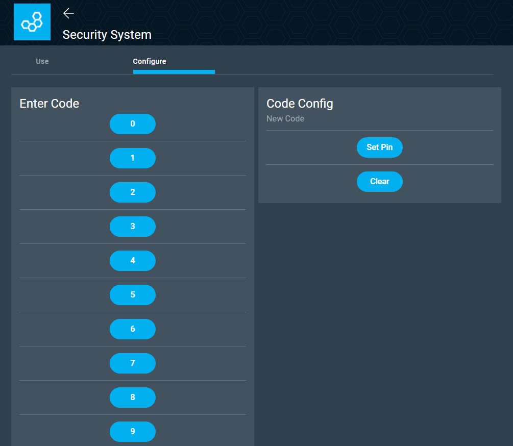
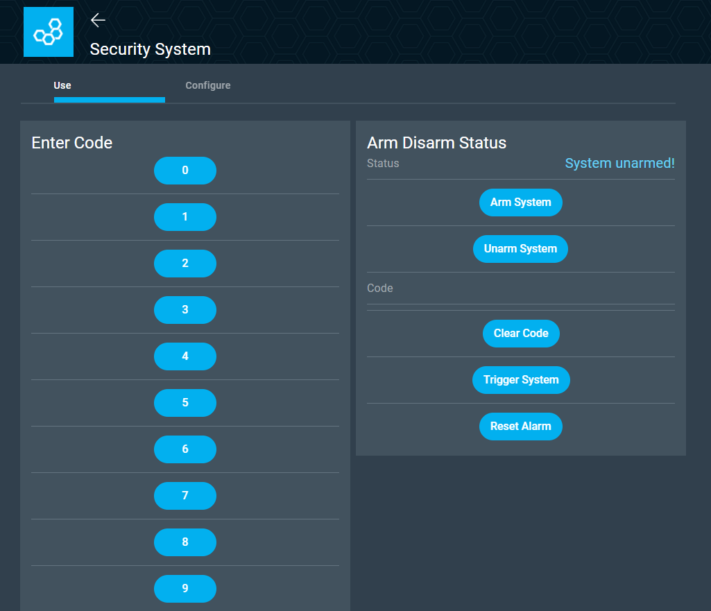
The interface on the dashboard will look like this. You can set a pin code and also delete the existing pin code by pressing the “Clear” button.
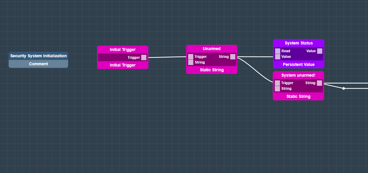
The next section we look at is the Security System Initialization.

The initial trigger object will start the system by itself. In the beginning the System is unarmed and the value for unarmed is saved in a persistent value object. A static string will then be send to the LCD with “System unarmed”.
The next section is used to arm the system. By pressing the interface button or pressing the * on the keypad the System Status will change.
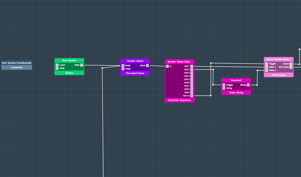
A value equal object will check whether the system is already armed, the system has no pin code yet or the system is now successfully armed.
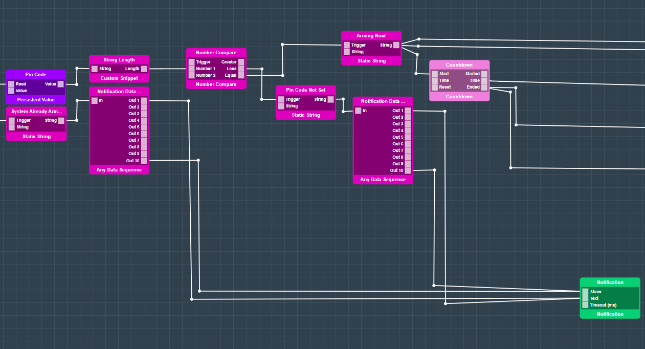
When the system is armed a countdown will begin and the buzzer will be hearable. The arming of the system will then by a static string be saved in a persistent value object. A string “System armed” will be send.
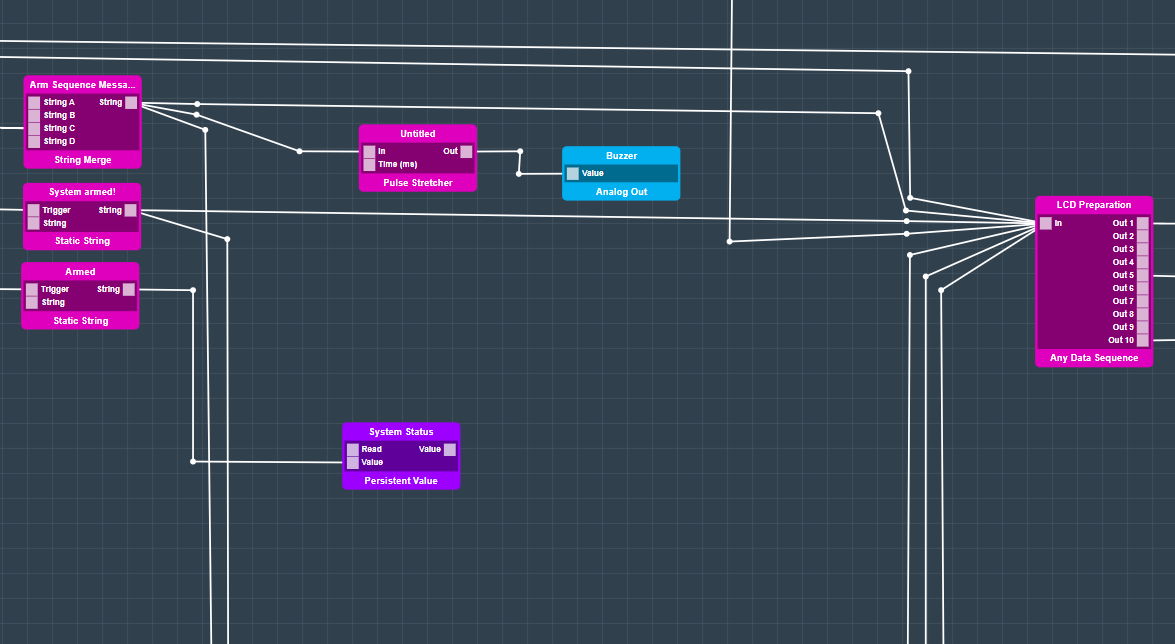
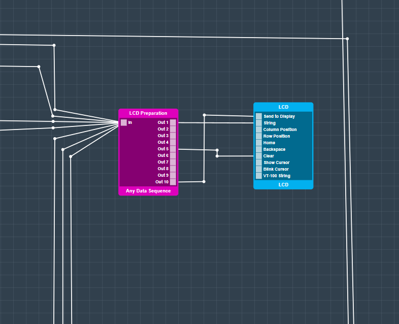
All strings with important messages like “System armed” will merge into a Data Sequence and then send to the LCD to be displayed.
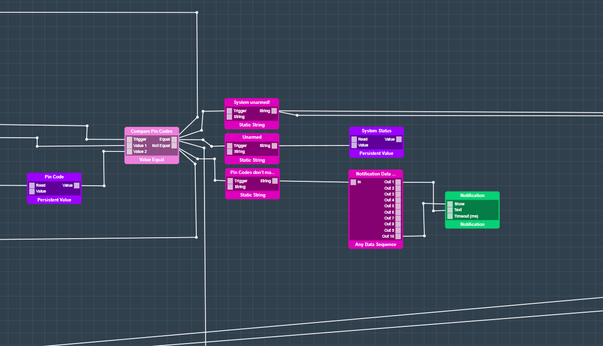
The next section is used to unarm the system. All button interface objects are connected to a trigger to number object and will be send out further.
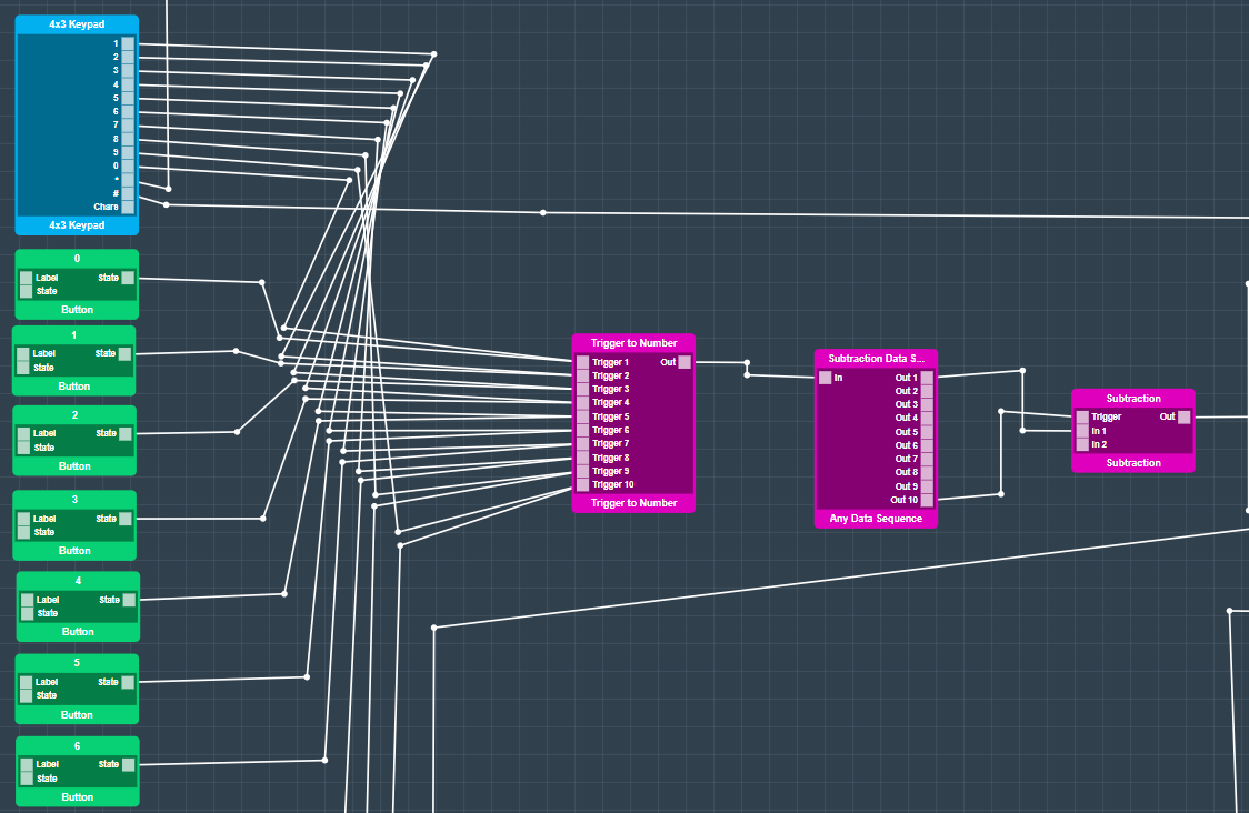
If you enter a number via the keypad or click on one of the buttons in the dashboard app the number gets displayed on the dashboard and also on the LCD.
Before that the system will check whether the entered code matches or doesn’t match the right pin code. Also it will check if at all a pin code was set and also whether the system is armed. When the system was not armed before a static string object will send “System unarmed” to the LCD to show that the system first needs to be armed. When the code is right the system status will change via the persistent value object and be saved.
The last section is used to reset the alarm and also trigger the system by interface buttons via the dashboard. The three hardware object refer to a door contact, a motion sensor and also the door sensor. Each of those hardware objects connected to the real sensors triggers the countdown and also the buzzer so you notice when someone enters without disarming the security system first.
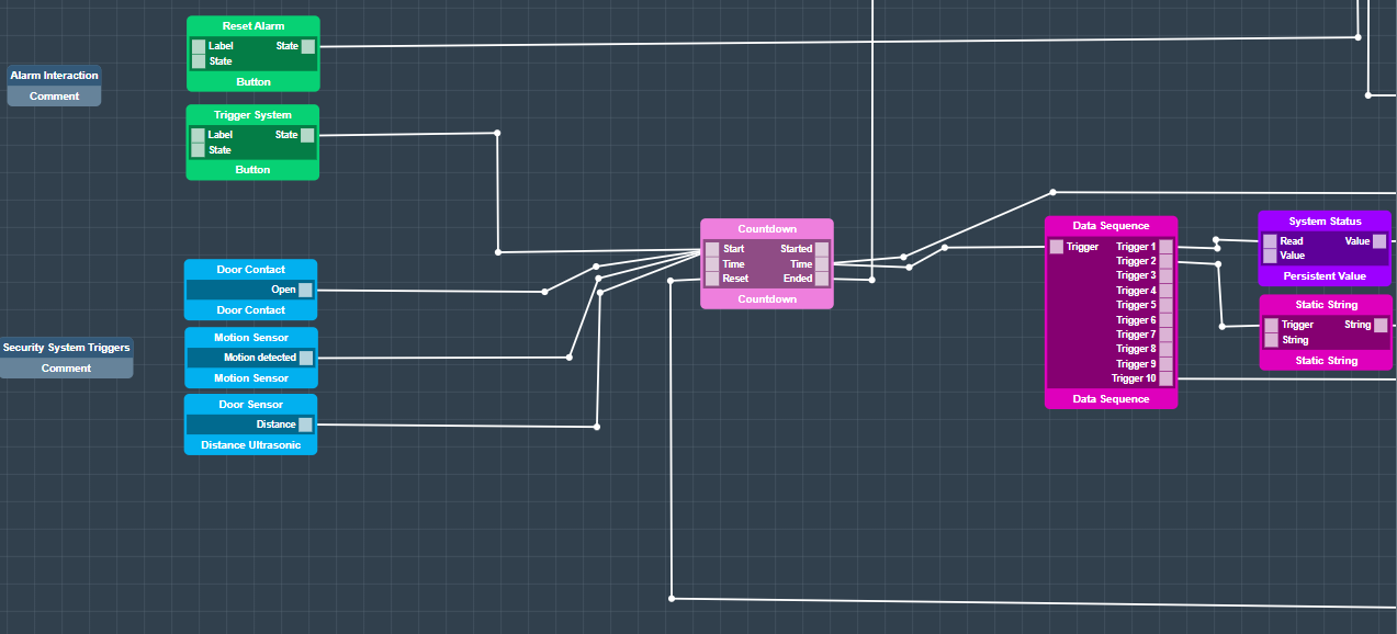
The LCD will prompt you that you have x seconds left to disarm the system. “Intruder Alert!” will be send to the LCD and also be displayed on the dashboard app itself.
All those interactions will look like this in the dashboard app. You can enter the code, arm and disarm the system and reset the alarm as well.
To enhance the system you could also integrate our SMS Notification system to get notified when someone is entering your home.
Map the Hardware
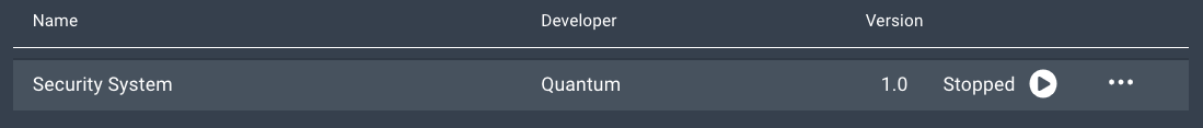
You should now be back on the Apps page.
Find your “Security System” app and hit the play button.
A list containing all of the devices in your application will expand.
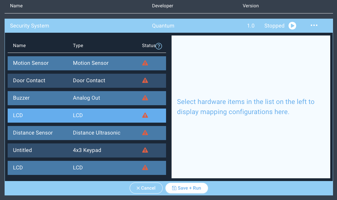
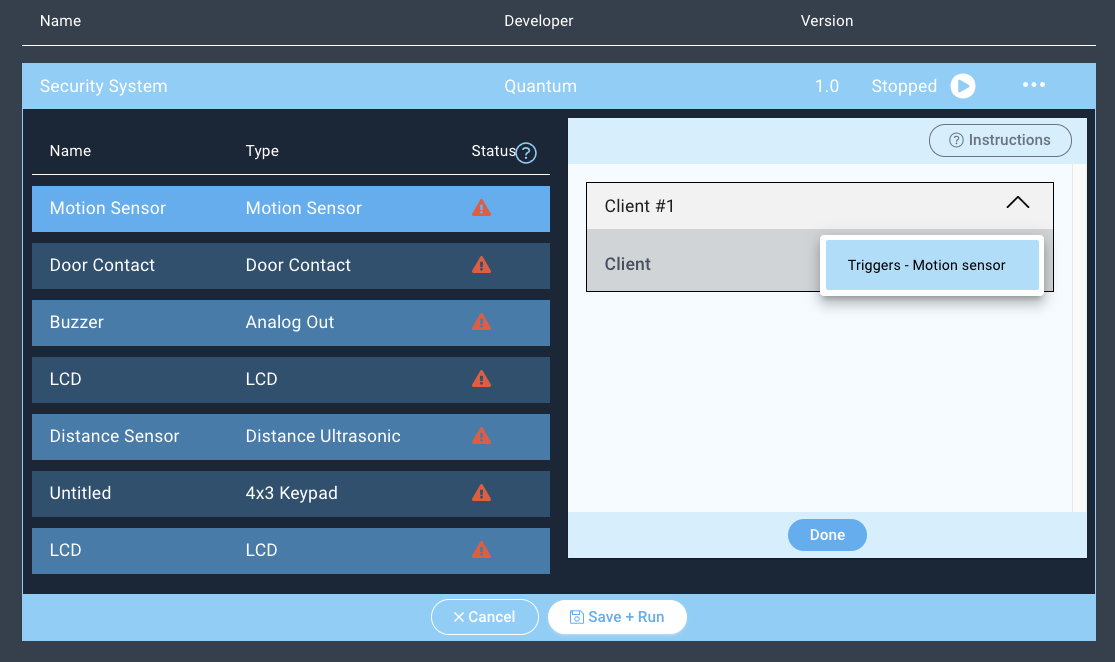
Next click on the “Motion Sensor” device and the client dropdown menu will appear on the right.
Select the Motion Sensor driver from the dropdown menu and hit “Done”.
Repeat the same steps for the remaining devices. For this application you should only have one selectable driver per device.
Notice how all but one of the status symbols have changed to green checkmarks. We have a door contact setup for use in our application, but we do not have one currently currently via Samsung SmartThings or one of our Builder Bases. So, you can leave this device unmapped, or you can pair one to the system.
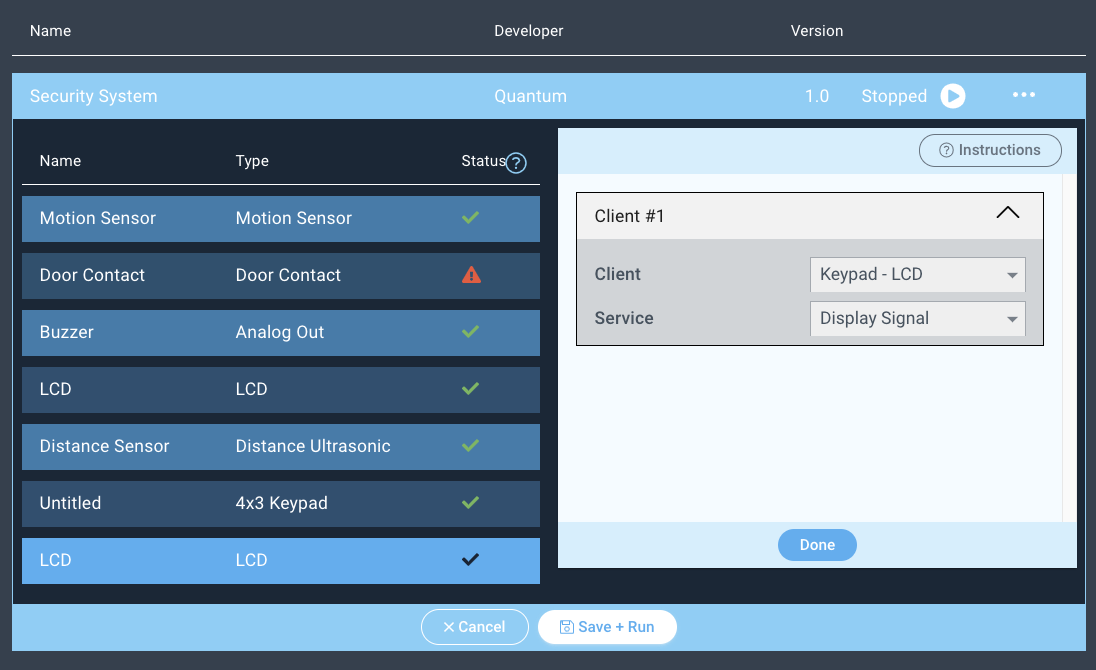
| Info |
|---|
When mapping firmware devices to objects in your Apps it is important to note that only devices and objects of the same type can be mapped together. Using this app for example, we are only given the option to map the client with the button firmware to the button object. |
You are now done mapping your application!
Next, hit “Save + Run”.
Run the App!
Congratulations! Your Security System is now complete, have fun!
Resources
Application |
| ||||||||
|---|---|---|---|---|---|---|---|---|---|
Firmware |
| ||||||||
Schematic |  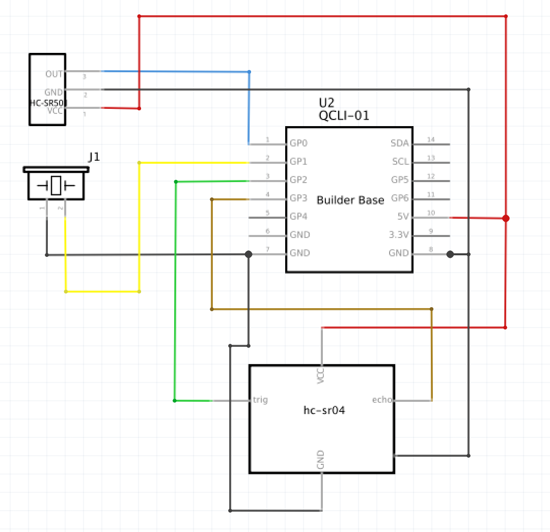 | ||||||||
Diagrams | | ||||||||
Files |
|