Overview
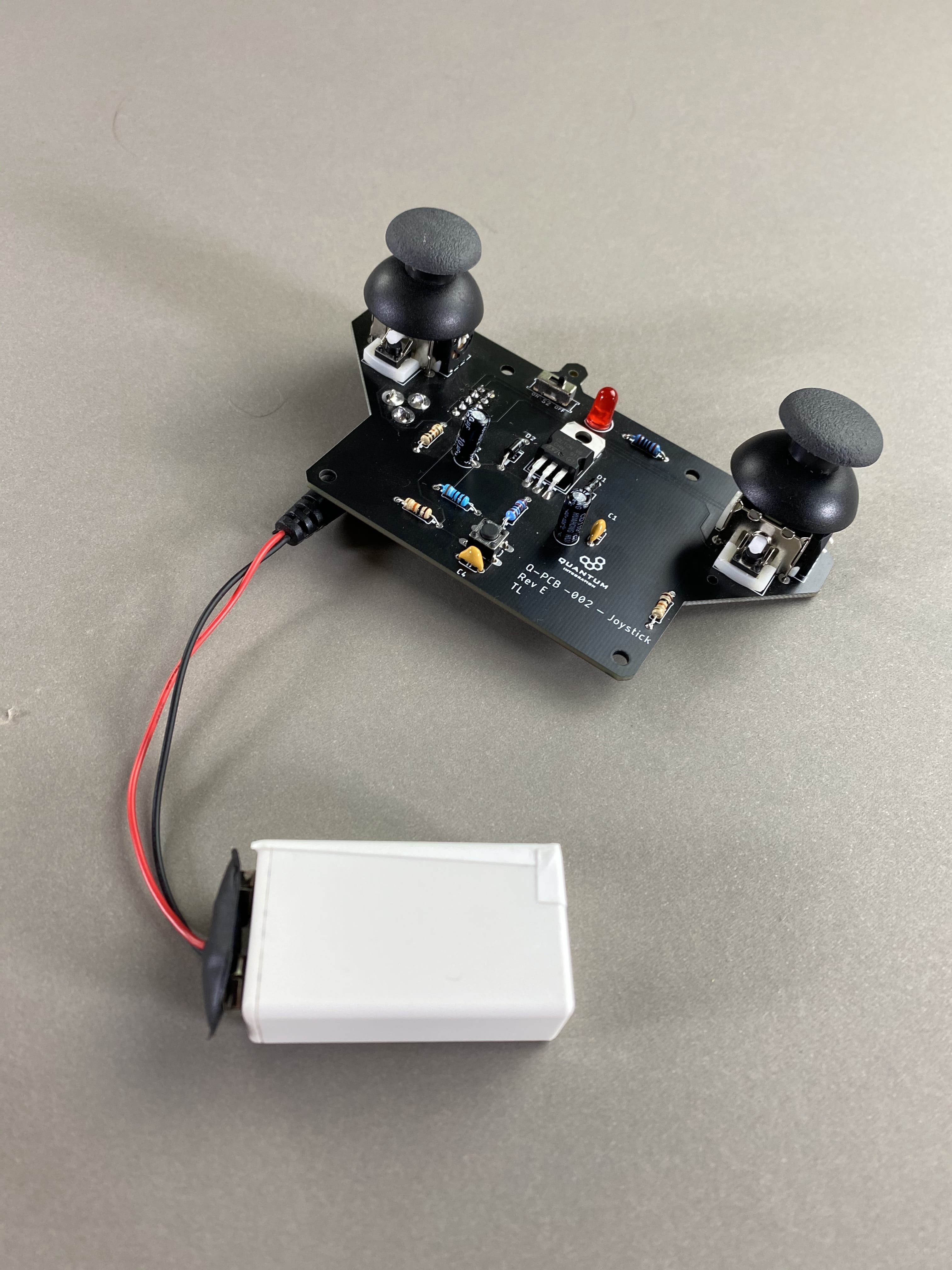
The Joystick DIY Kit allows one to control numerous projects with the Quantum platform, like a remote controlled car or a robotic arm.
INTERMEDIATE | $7 - $15 | 1 HOUR | 1 CLIENT |
Things used in this project
Hardware components
Picture | Name | Quantity | Price(As of 7/10/20) | Link |
|---|---|---|---|---|
 | Radial LED (5mm) | 1 | $.05/LED (when purchased in a 100 pack) | Included in Starter Kit Or you can purchase it here |
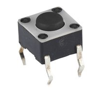 | Tactile Push Button | 1 | $.32/Button | Included in Starter Kit Or you can purchase it here |
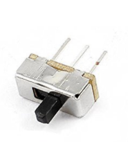 | Sliding Switch | 1 | ~$.26/Switch | Can be purchased here |
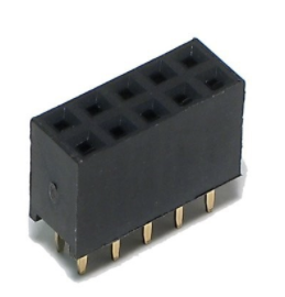 | 2x5 Pin Header | 1 | ~$.67/Header | Can be purchase here |
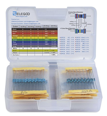 | 100Ω Resistor | 1 | $.02/Resistor | Can be purchased here |
| 10kΩ Resistor | 3 | $.02/Resistor | Included in Starter Kit Or you can purchase it here |
| 240Ω Resistor | 1 | $.02/Resistor | Can be purchased here |
| 390Ω Resistor | 1 | $.02/Resistor | Can be purchased here |
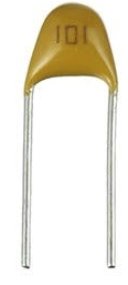 | 100nf Capacitor | 1 | ~$.03/Capacitor | Can be purchased here |
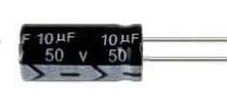 | 10uf Polarized Capacitor | 1 | ~$.03/Capacitor | Can be purchased here |
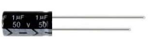 | 1uf Polarized Capacitor | 1 | ~$.03/Capacitor | Can be purchased here |
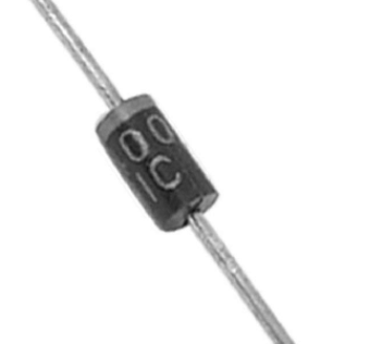 | 1N4000 Diode | 2 | ~$.24/Diode | Can be purchased here |
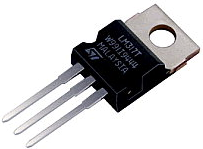 | LM317MB | 1 | ~$.64/Regulator | Can be purchased here |
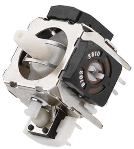 | Thumb Joystick | 2 | ~$1.85/Joystick | Can be purchase here |
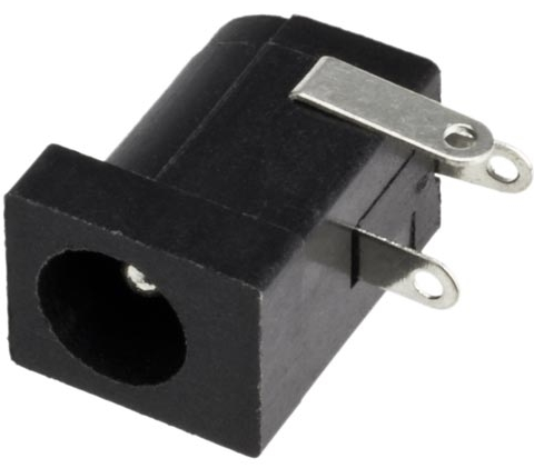 | 2.1mm Barrel Jack | 1 | $.60 | Can be purchased here |
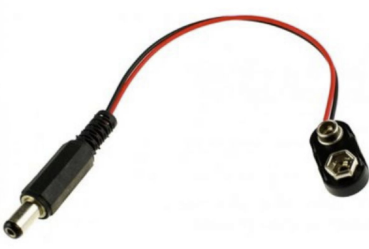 | 2.1mm Barrel Jack to 9V adapter | 1 | ~$1.2/Adapter | Can be purchased here |
 | Joystick DIY Kit Board | 1 | $2-4 (5 Pack) | - |
 | Q-Client Builder Base | 1 |
Tools Used
Picture | Name | Quantity | Link |
|---|---|---|---|
 | Small slotted-head screwdriver | 1 | Included in the Starter Kit or you can pick from one on our Recommended Tools List |
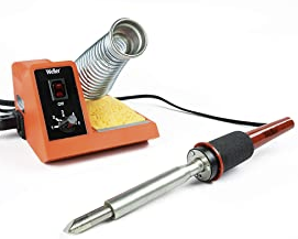 | Soldering Iron | 1 | You can pick from one on our Recommended Tools List |
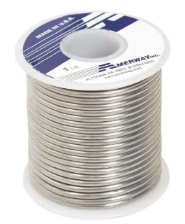 | Solder | 1 | You can pick from one on our Recommended Tools List |
 | Diagonal Cutters | 1 | You can pick from one on our Recommended Tools List |
 | Work Holder | 1 | You can pick from one on our Recommended Tools List |
Story
The Idea
The motivation behind creating the Joystick DIY Kit is to offer a project that is simple to build and highly versatile to use. With this Joystick Kit you are able to easily control a wide variety of motorized projects.
Video
Build Process
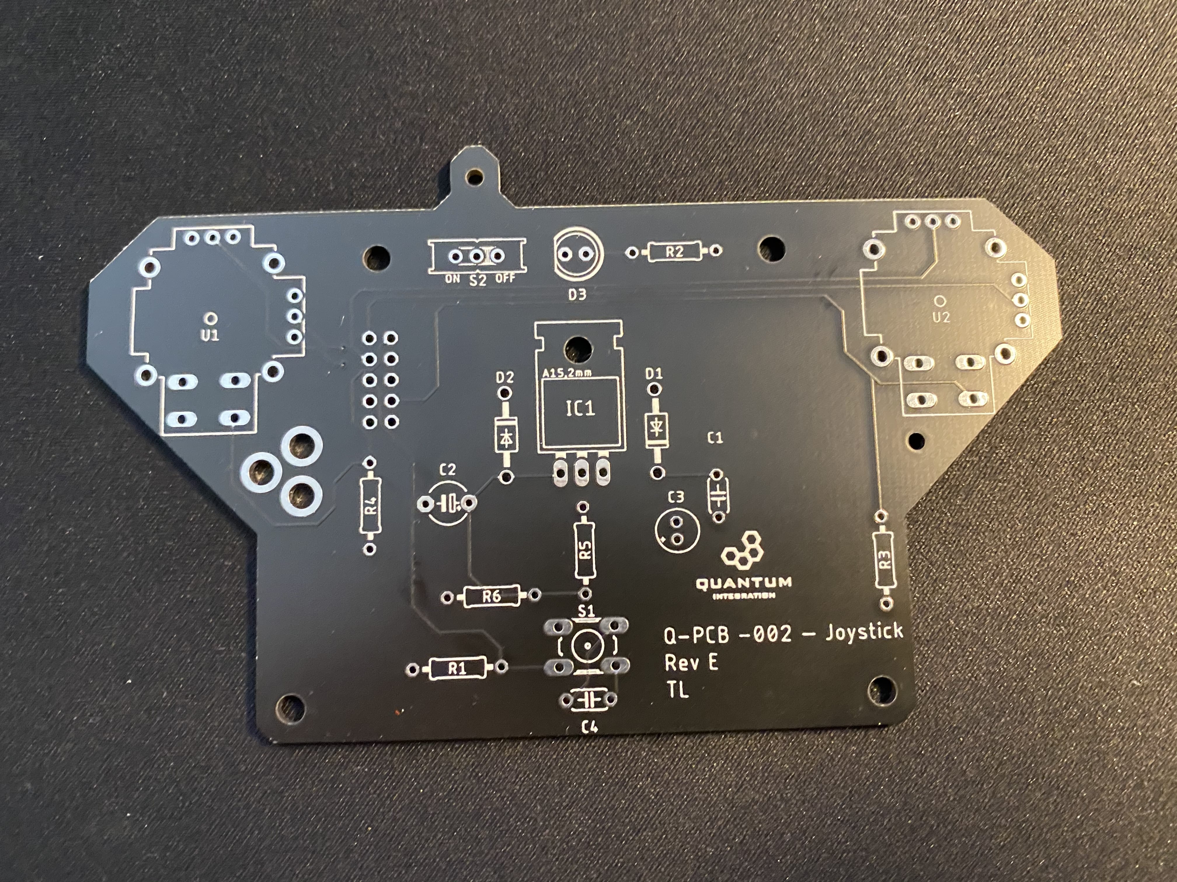
Step 1: PCB Assembly and Soldering
Download the Joystick Kit Bill of Materials:
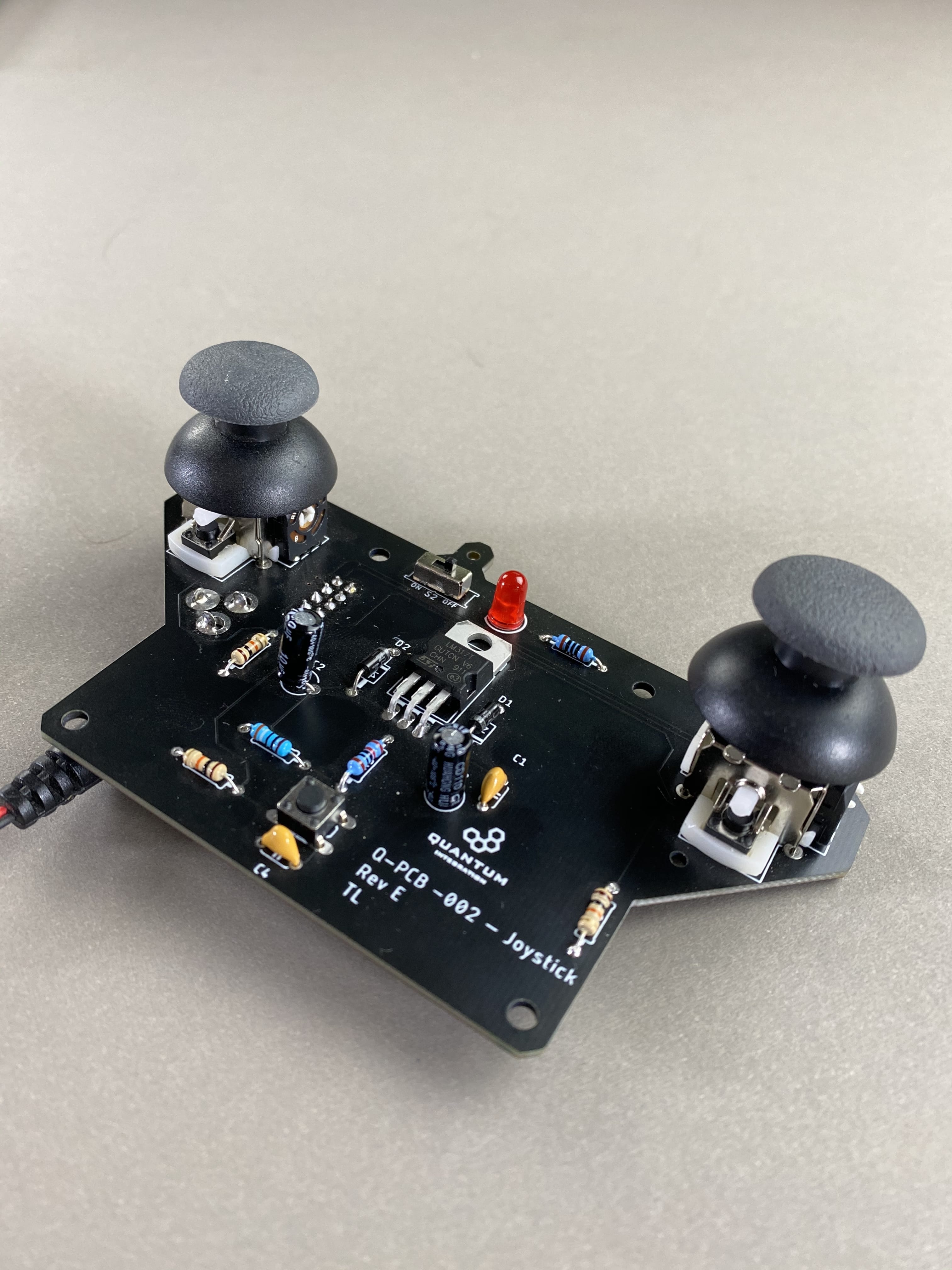
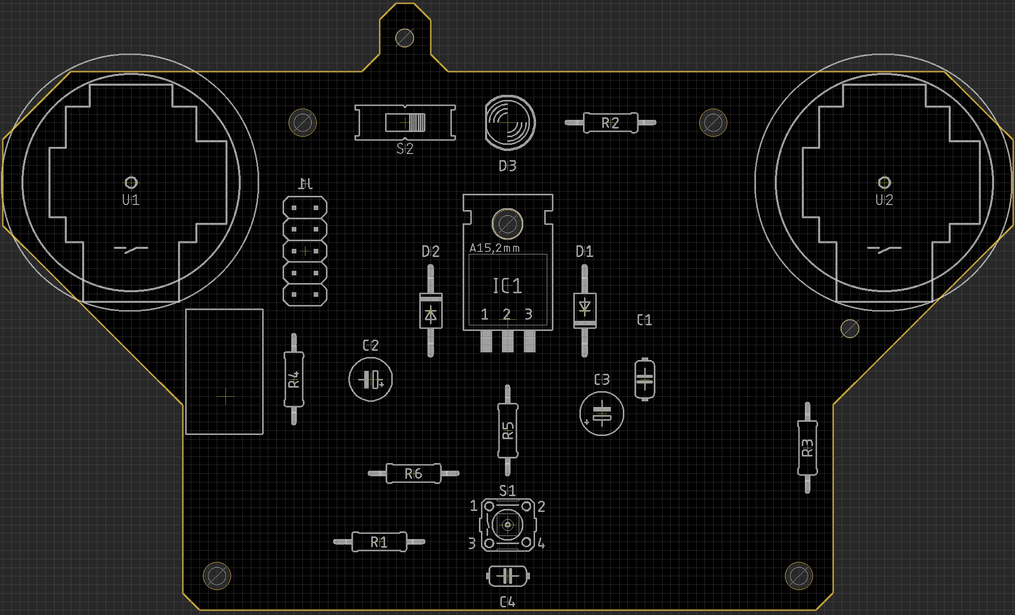
Gather your Joystick Kit PCB and all required components listed in the BOM.
It is especially important to follow the BOM exactingly as it tells you where to place the components on the PCB. The fifth column on the BOM is the “parts” column. This column designates which position on the PCB you are to pace the component. For example, if under the parts column you have a resistor labeled r1 you would then find the position marked r1 on the PCB and place the resistor there.
Using some form of work holder is advised. You can find a list of suitable work holders on our Recommended Tools List.

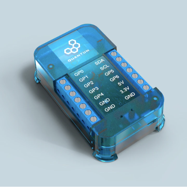
Step 2: Wiring your Joystick to the Builder Base
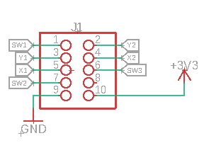
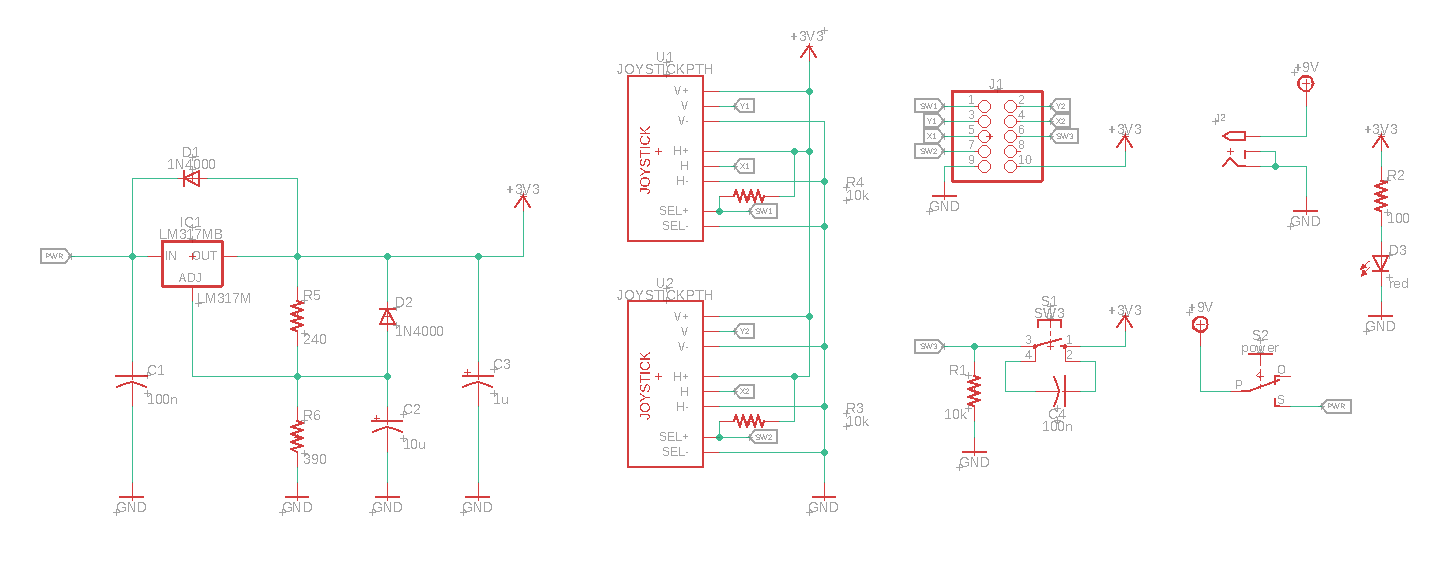
On the back of your Joystick PCB you will have a 2x5 header. This is where you will plug in your cables to the client.
The table below shows how each terminal on the 2x5 header corresponds to the Joystick and button components on the PCB
Left Joystick | Right Joystick | Button |
|---|---|---|
SW1 | SW2 | SW3 |
Y1 | Y2 | |
X1 | X2 |
From the two diagrams below you can see how we wired the 2x5 header to the Builder Base.
2x5 Header
Builder Base
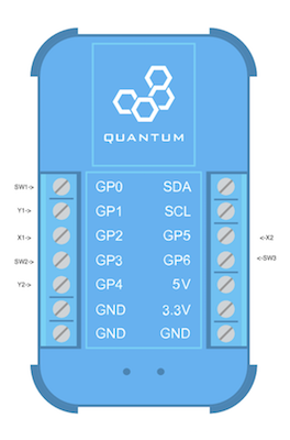
First we will start by connecting the GND and 3.3V terminals to the GND and 3.3V ports respectively on the Builder Base.
Be careful to make sure that you connect the Joystick to 3.3V and not 5V. If you don’t the readings from the joystick will be off.
Then we connect the remaining header terminals to the builder base as follows:
SW1 → GP0
Y1 → GP1
X1 → GP2
SW2 → GP3
Y2 → GP4
X2 → GP5
SW3 → GP6
Step 3: Build the Firmware
Remember: All Apps and Firmware Files are available in the resources section at the bottom of the page!
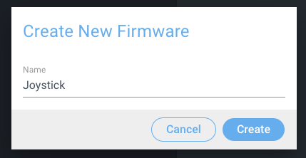
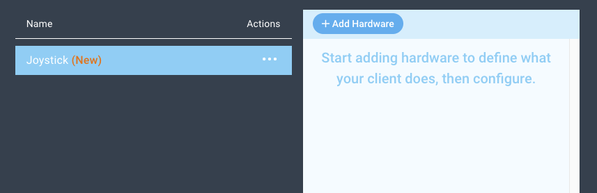
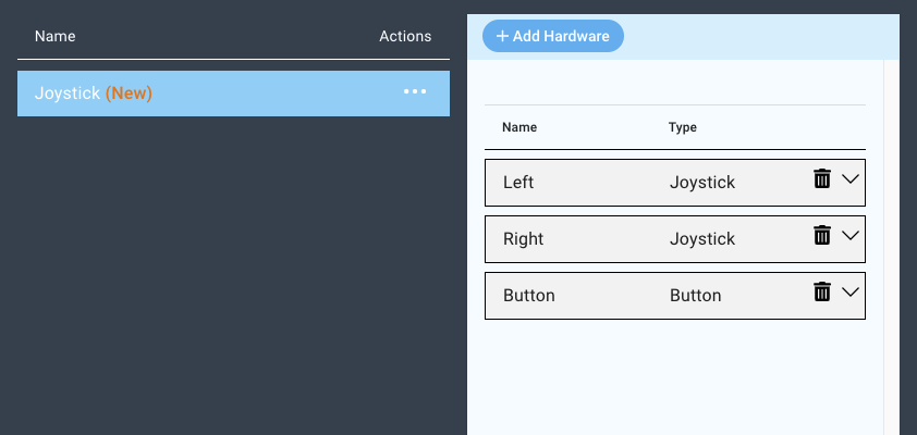
Navigate to the Firmware Builder and create a new Firmware file. We named ours Joystick.
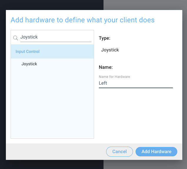
Next, click the “+ Add Hardware” button and find the Joystick device via the search bar, select it, name it, and then click “Add Hardware”. We named ours Left.
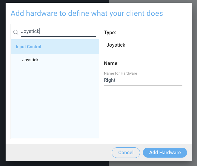
Now, add another device by clicking the “Add Hardware” button again, and add another Joystick. We named this one “Right”.
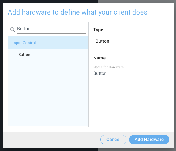
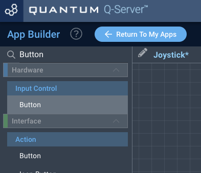
Lastly, we will add one more device. Repeat the steps above to add another device, but this time search for a “Button”.
You should now have three devices in your firmware file.
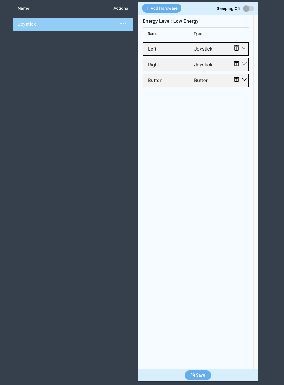
Now you can follow this video to configure each device in the firmware file.
You have now finished configuring your firmware. Save your firmware by clicking the “Save” button at the bottom of the screen.
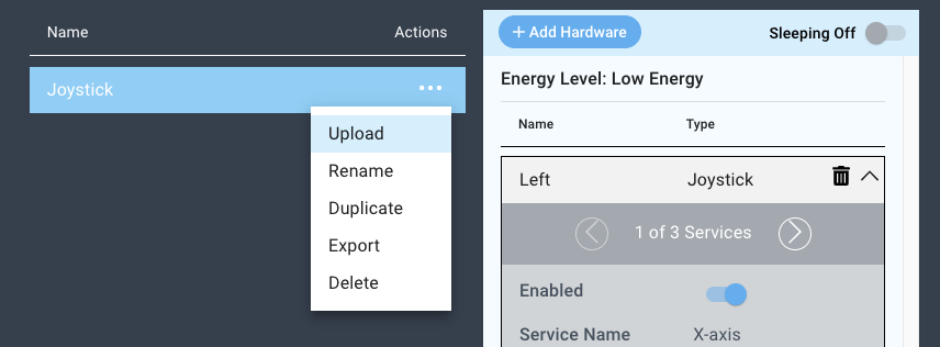
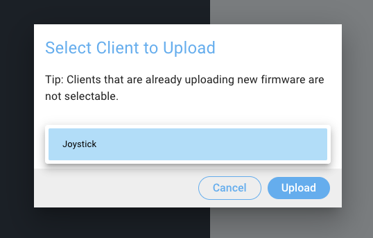
Now you can upload your firmware to the Build Base.
Step 4: Build the Application
Remember: All Apps and Firmware Files are available in the resources section at the bottom of the page!
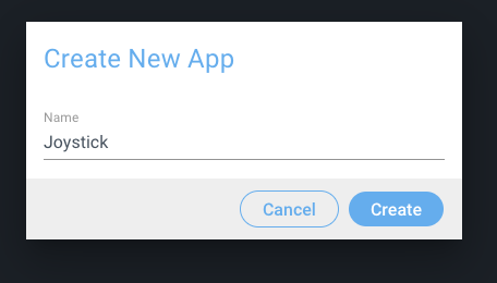
Navigate to the Applications page and click the “+ Create New Button”, name your application, and click create.
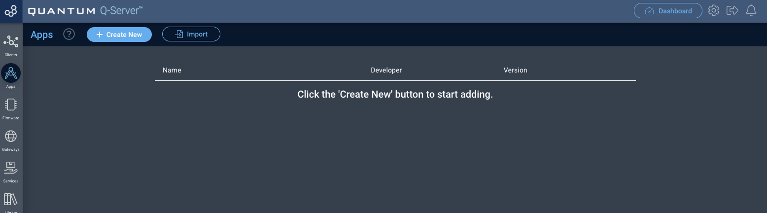
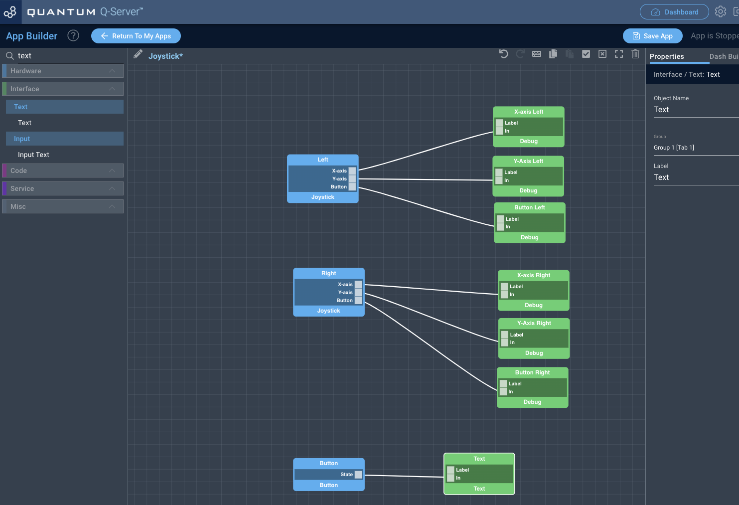
You will now be directed to the App Builder Canvas.
Using the search bar in the left hand tool-bar search for the Joystick code object and drag it onto the canvas.
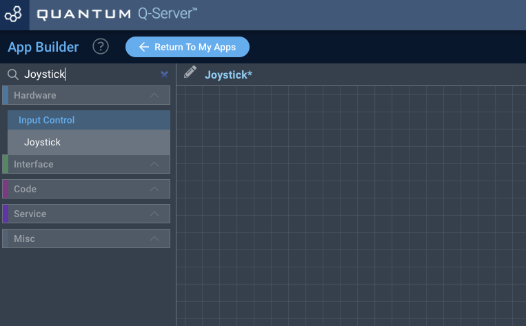
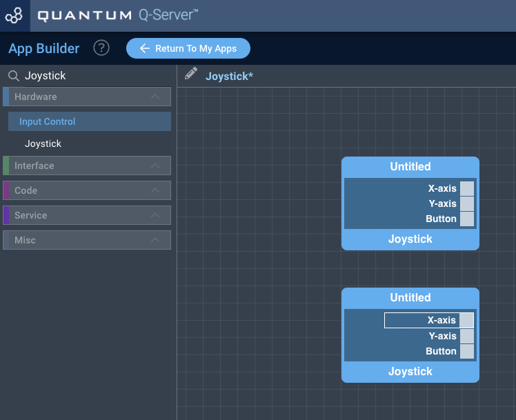
We will now name the Joystick code objects by clicking on them and editing their name in the right hand “properties” panel.
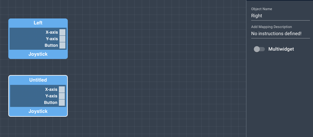
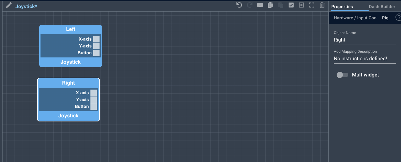
In order to save the names you must click the “Save Properties” button at the bottom of the properties tab.

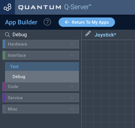
Next, search for the “Debug” code object using the search bar and drag six of them onto the canvas.
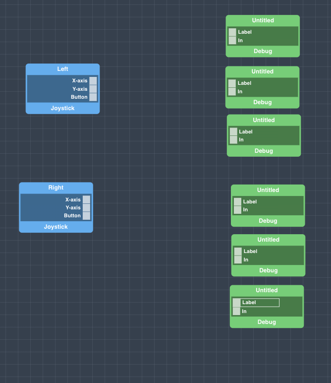
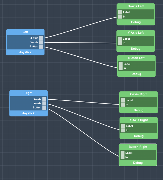
Now, for each Joystick connect the three output ports to each of their own Debug objects via the “In” port on the debug objects.
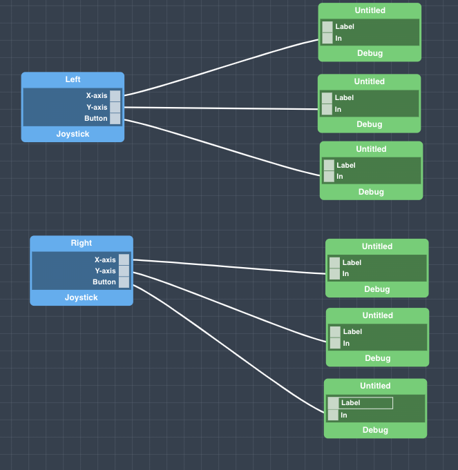
At this point we suggest that you name each of the Debug objects and Label them. To name and label an object click on the object and name it via the properties tab on the right hand side of the canvas.
Remember to hit the “Save Properties” tab at the bottom of the properties tab for each object, otherwise your names and labels will not be saved!
Now search for the “Button” and “Text” objects and drag both onto the canvas.
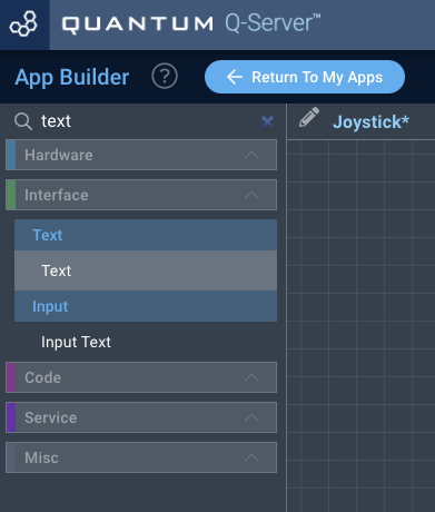
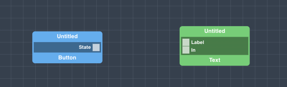
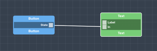
Connect the “State” port from the button to the “In” port on the text object, and name and label your objects as you did with the other objects in the previous section.
Now, save your App by clicking the “Save App” button in the upper right hand side of the canvas.
Your app is now complete!
Step 5: Map Your Application
You should now be back on the Apps page.
Find your “Joystick” app and hit the play button.
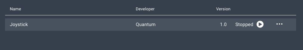
A list containing all of the devices in your application will expand.
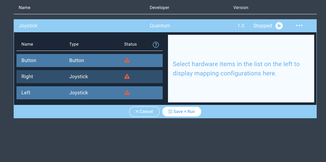
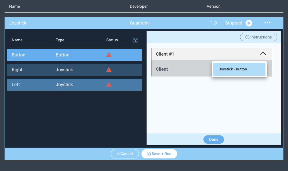
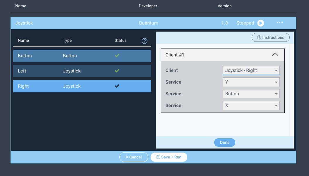
Next click on the “Button” device and the client dropdown menu will appear on the right.
Select the Button driver from the dropdown menu and hit “Done”.
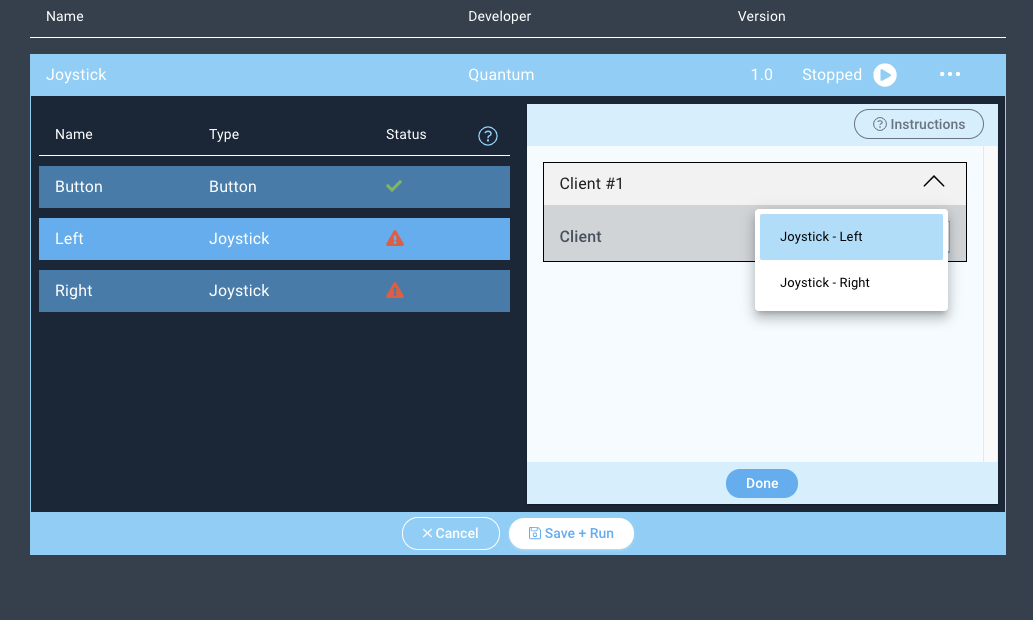
Repeat the same steps for the “Right” and “Left” Joystick devices.
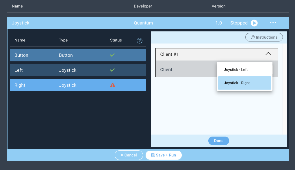
Notice how the status symbols have changed to green checkmarks.
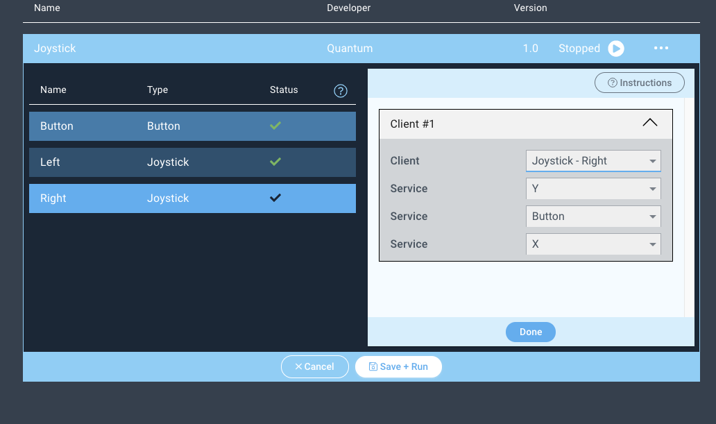
When mapping firmware devices to objects in your Apps it is important to note that only devices and objects of the same type can be mapped together. Using this app for example, we are only given the option to map the client with the button firmware to the button object.
Step 6: Run the Application!
Next, hit “Save + Run”
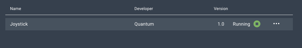
Congratulations! Your Joystick project is now complete! You can now use this as input control for RC cars and other motorized projects!
Code
App
Firmware
Gallery
Resources
App | |
|---|---|
Firmware | |
Schematic | |
BOM | |
Gerber Files | |
Final Rev E |