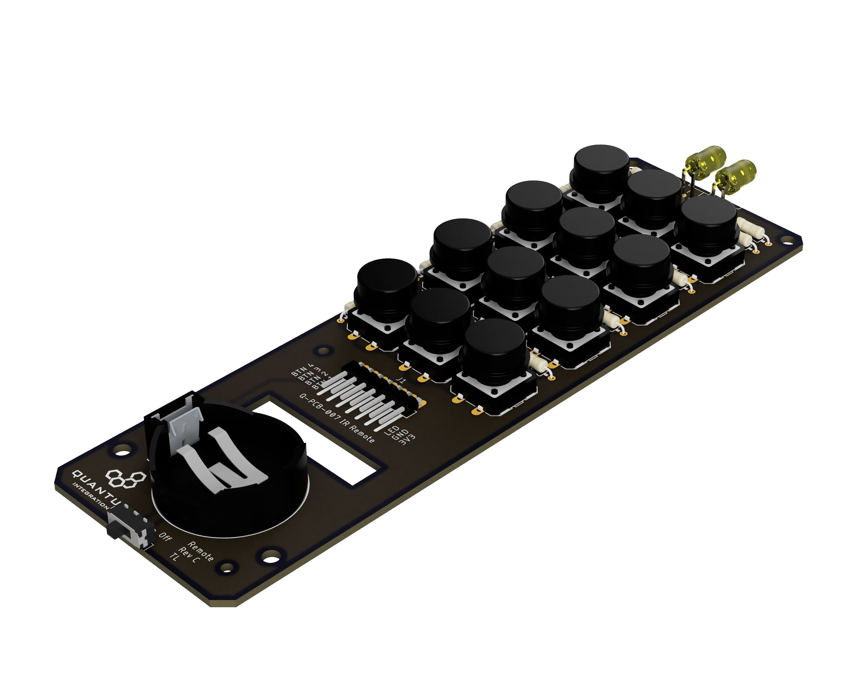
Overview
This is not just another remote to control your TV. The IR Remote DIY kit includes a series of buttons and an IR emitter that can be used in conjunction with the Quantum system to create the ultimate universal remote. This DIY kit will allow you to control any component connected to the Quantum system, countless IR devices, and supported IoT platforms. What you program your remote to do is up to you. You can even create “Scenes” that can, if you choose, use one button to do all of that. Why not program a “Movie Night” button that can turn off the lights, roll down the shades, turn on the TV, and adjust the input of the TV and receiver to the movie inputs? Add an “intermission mode” to pause your movie and brighten the lights for a safer trip to the kitchen to make more popcorn. The possibilities are limited only by your imagination.
INTERMEDIATE | $14.99 |
Hardware Components
The components are part of the DIY Kit or can be sourced separately with help of the BOM:
Picture | Name | Designator | Quantity |
|---|---|---|---|
Infrared-clear LED | D1 | 1 | |
Red-clear LED | D2 | 1 | |
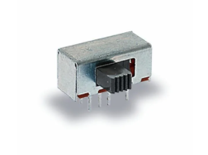
| Sliding Switch | S13 | 1 |
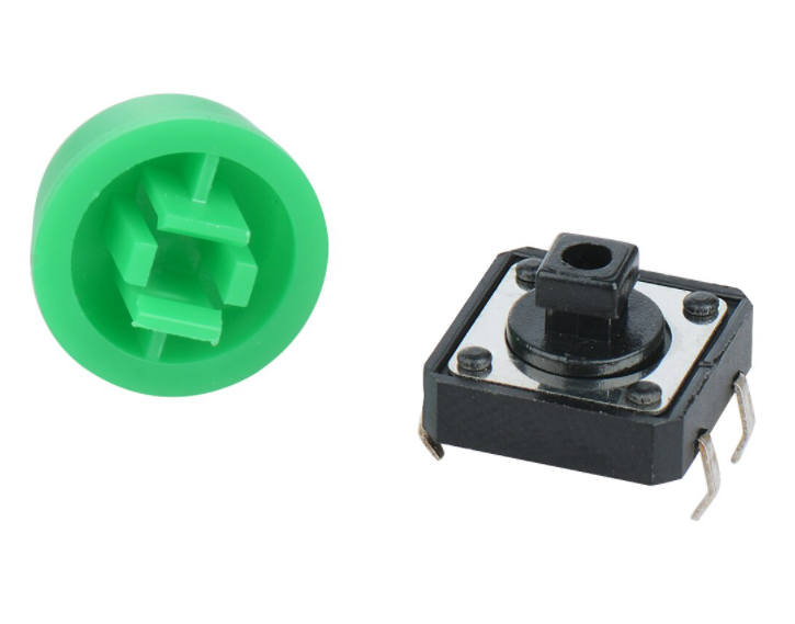 | Tactile button (12x12mm) with color cap (Green) | S1, S2, S3 | 3 |
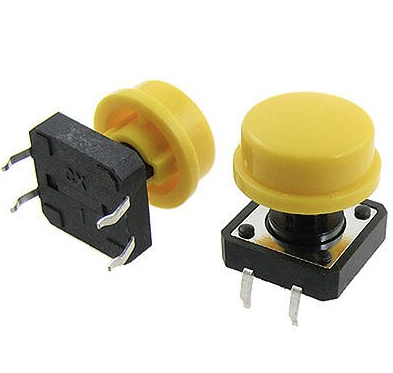 | Tactile button (12x12mm) with color cap (Yellow) | S4, S5, S6 | 3 |
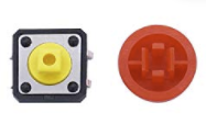 | Tactile button (12x12mm) with color cap (Red) | S7, S8, S9 | 3 |
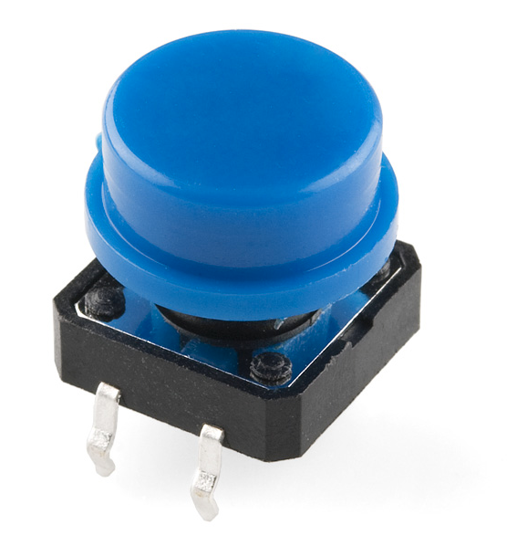 | Tactile button (12x12mm) with color cap (Blue) | S10, S11, S12 | 3 |
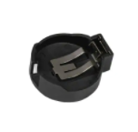 | Battery Holder | B1 | 1 |
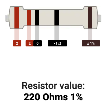
 | 220 Ω Resistor | R1 | 1 |
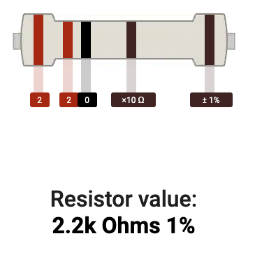
 | 2.2 kΩ Resistor | R2 | 1 |
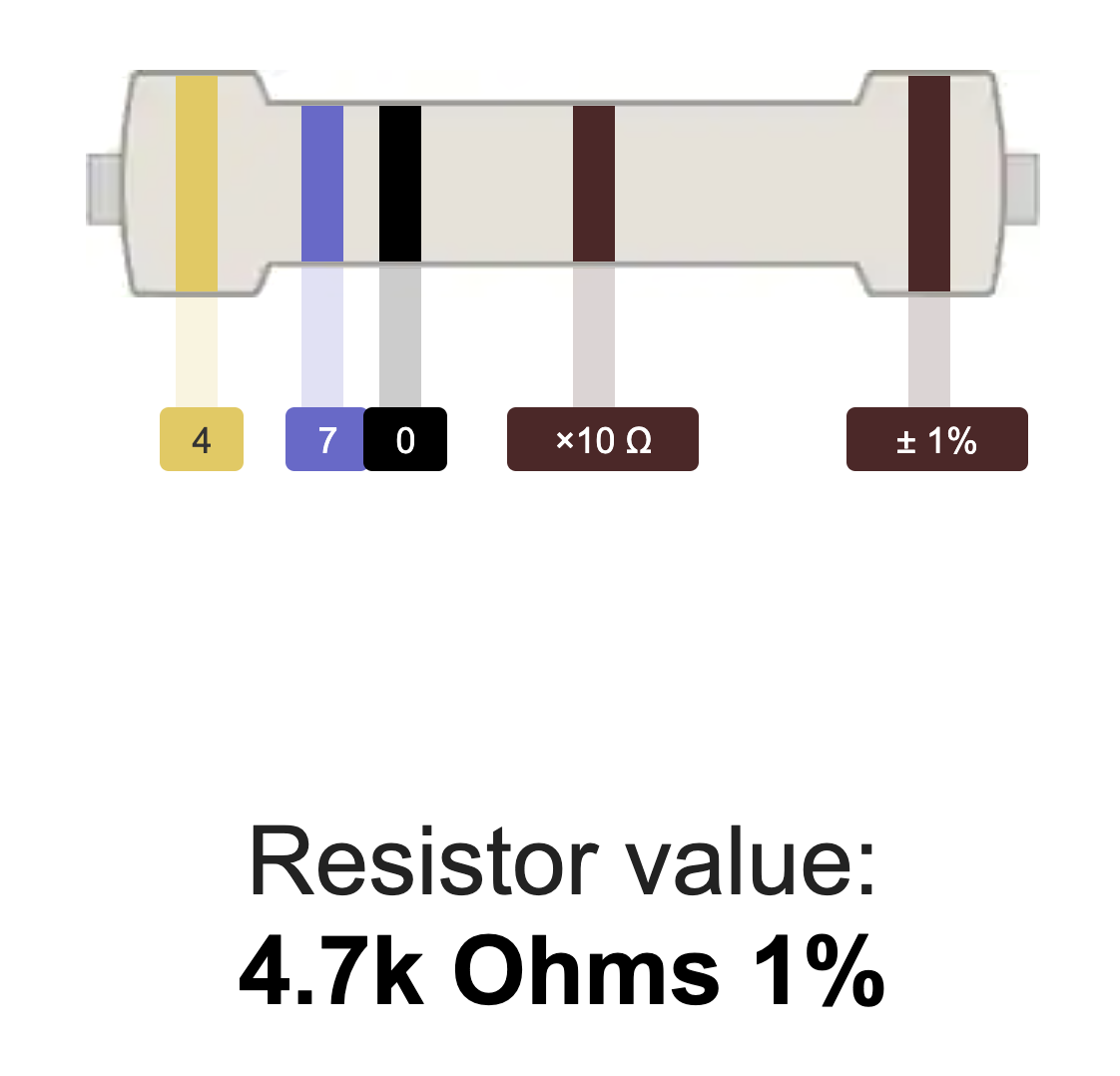 | 4.7 kΩ Resistor | R5, R6, R12, R16 | 1 |
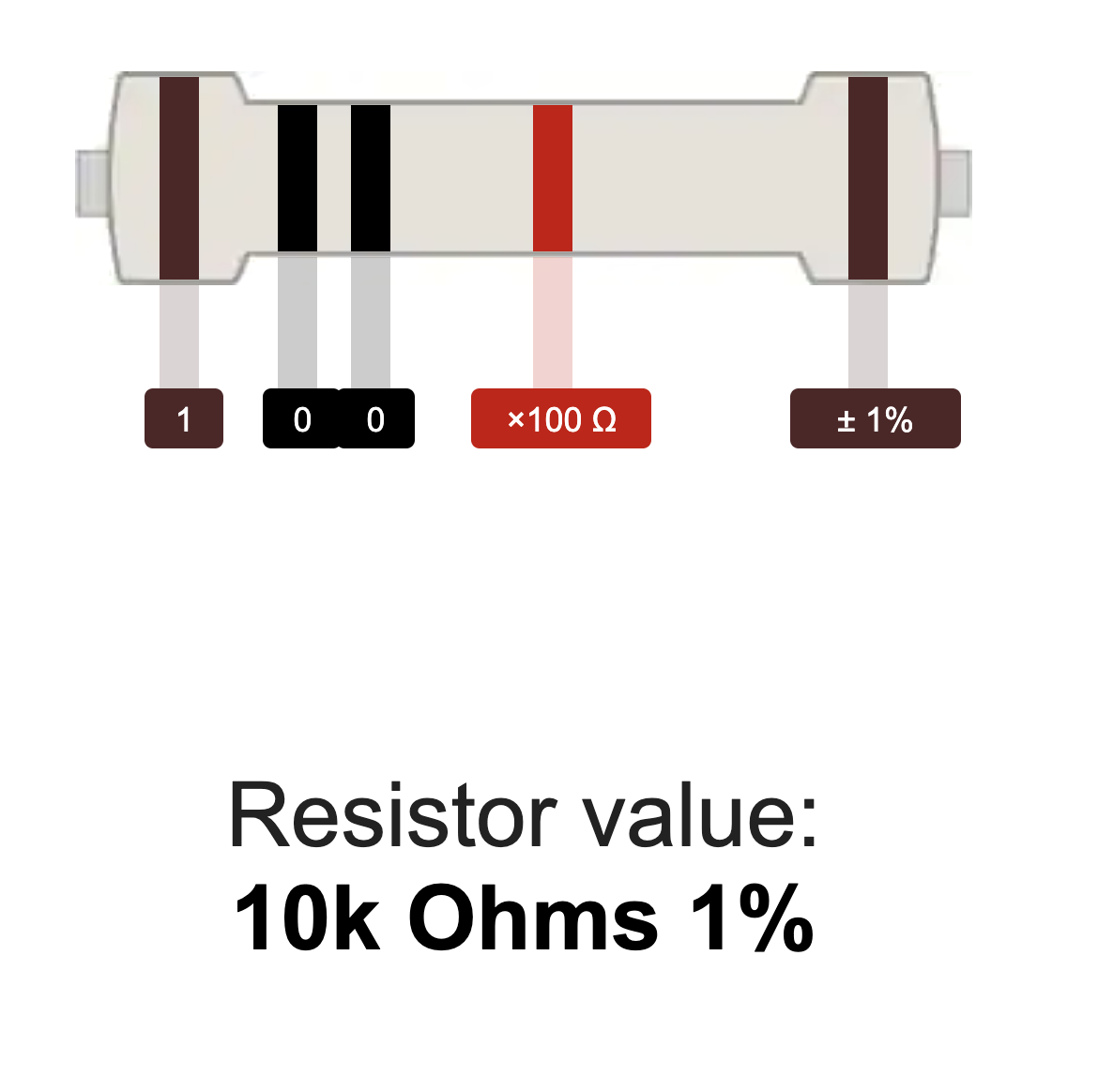 | 10 kΩ Resistor | R3, R4, R7, R9, R11, R13, R15, R17 | 3 |
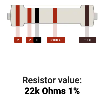
 | 22k Ω Resistor | R8, R10, R14, R18 | 1 |
 | 1x2 2.54mm Terminal Block | J1 | 3 |
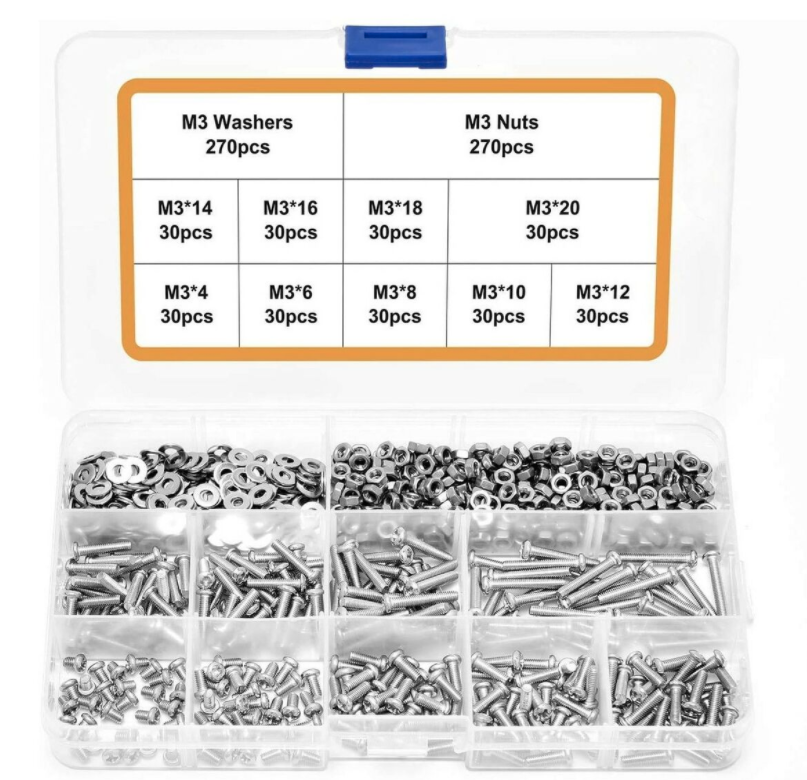 | Mounting Hardware
| 10 | |
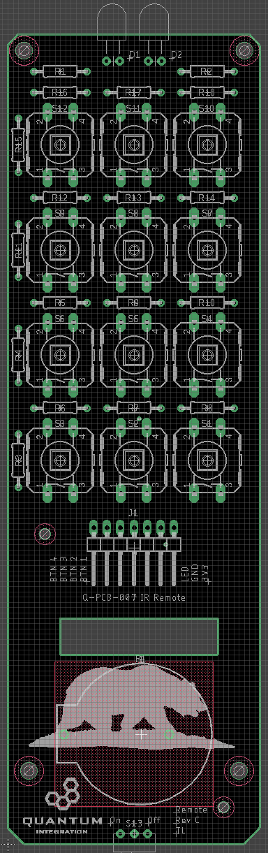
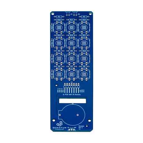 | IR Remote PCB | Q-PCB-007 | 1 |
Tools Used
Picture | Name | Quantity | Link |
|---|---|---|---|
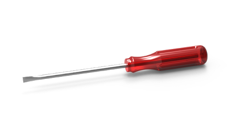 | Small flat-head screwdriver | 1 | Included in Component Kit or you can pick from one on our Recommended Tools List |
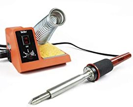 | Soldering Iron | 1 | You can pick from one on our Recommended Tools List |
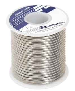 | Solder | 1 | You can pick from one on our Recommended Tools List |
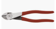 | Diagonal Cutters | 1 | You can pick from one on our Recommended Tools List |
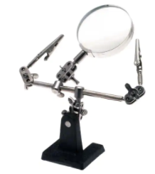 | Work Holder | 1 | You can pick from one on our Recommended Tools List |
PCB Assembly and Soldering
Place groups of components on the board and then solder them to the pads.
Using some form of work holder is advised. You can find a list of suitable work holders on our Recommended Tools List.
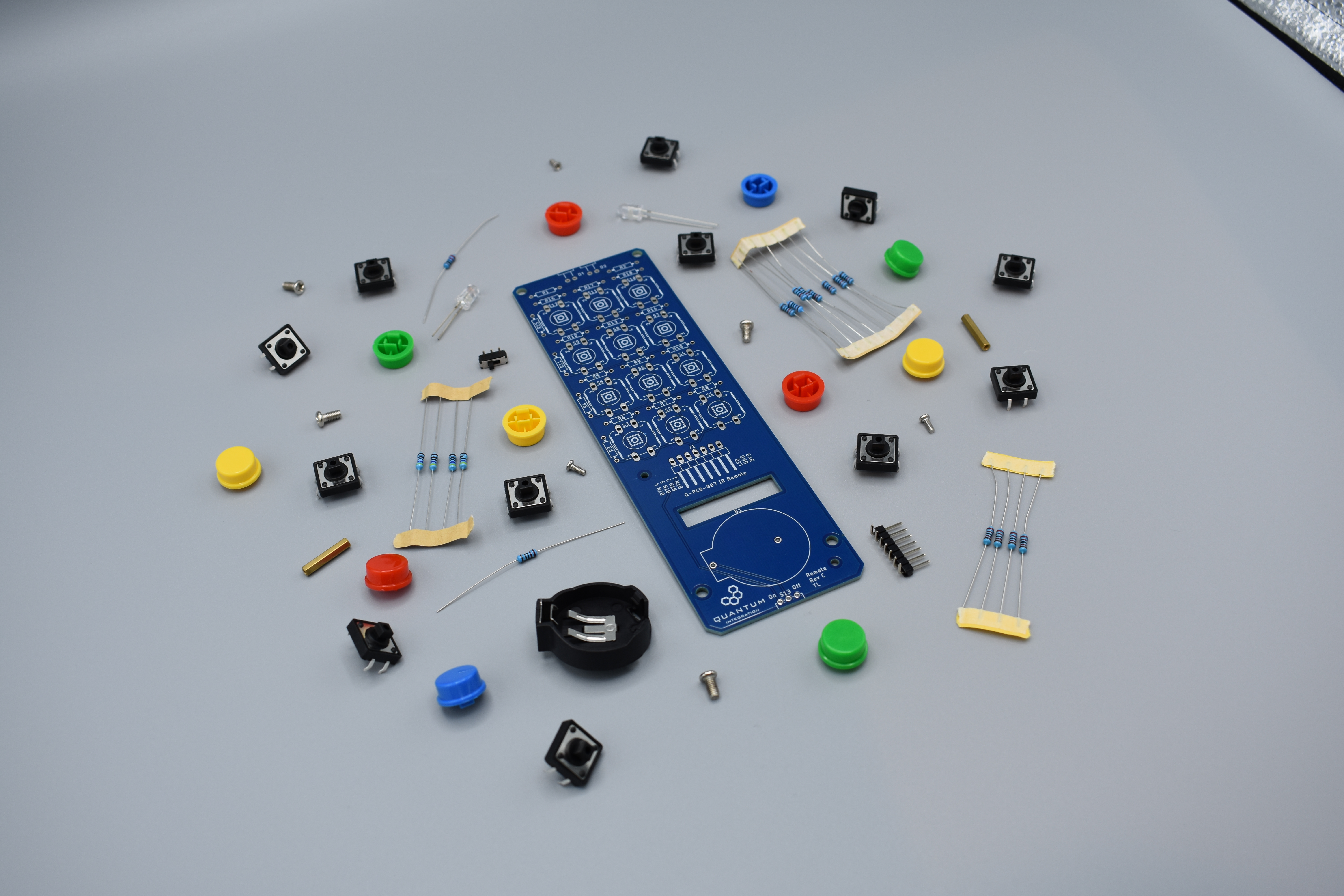
We start by putting all parts on the table.
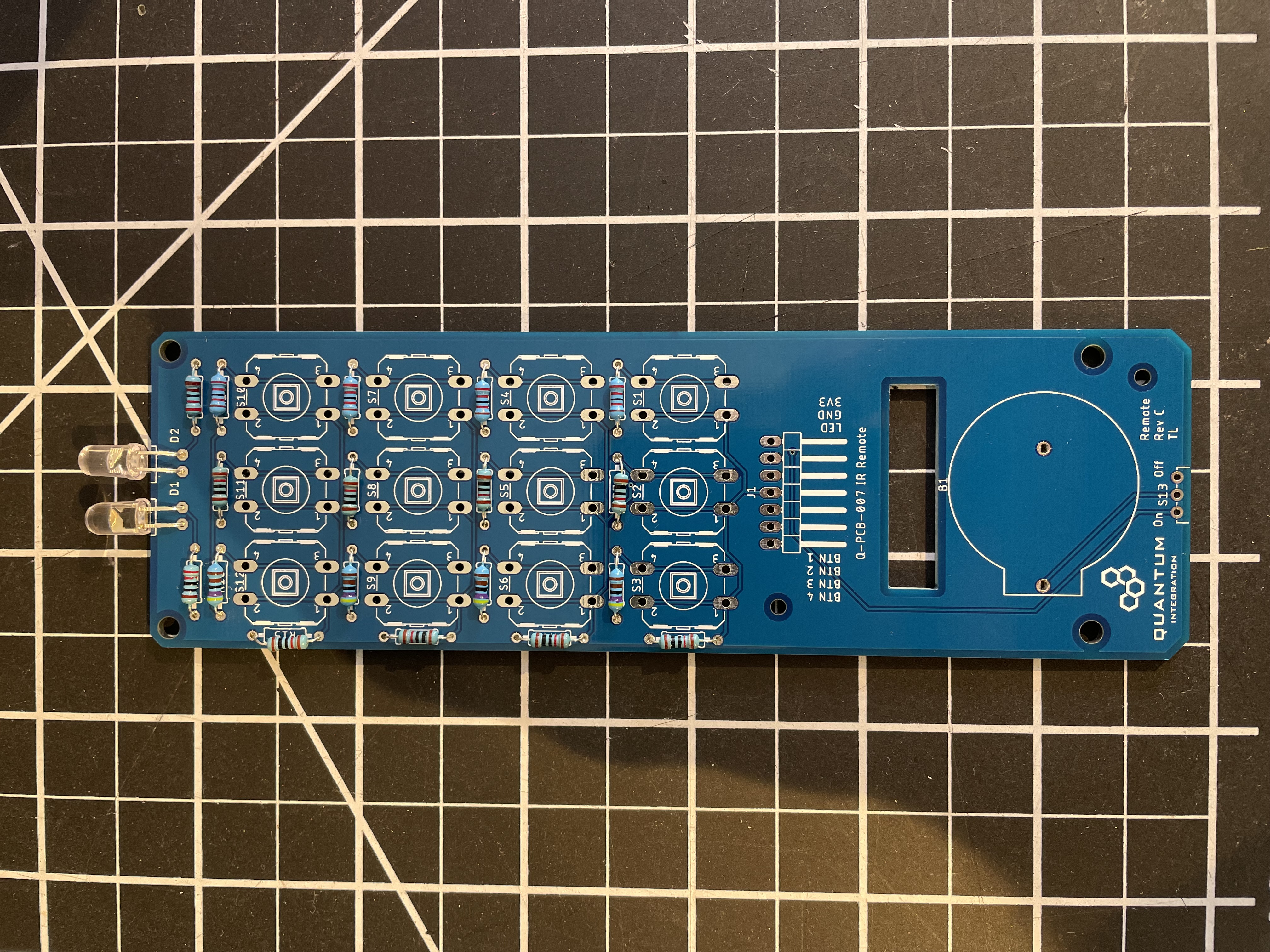
Start by soldering the resistors. Use the table and pictures to identify them.
220Ω Resistor: R1
2.2kΩ Resistor: R2
4.7kΩ Resistor: R5, R6, R12, R16
10kΩ Resistor: R3, R4, R7, R9, R11, R13, R15, R17
22kΩ Resistor: R8, R10, R14, R18
 |  |  | |  |
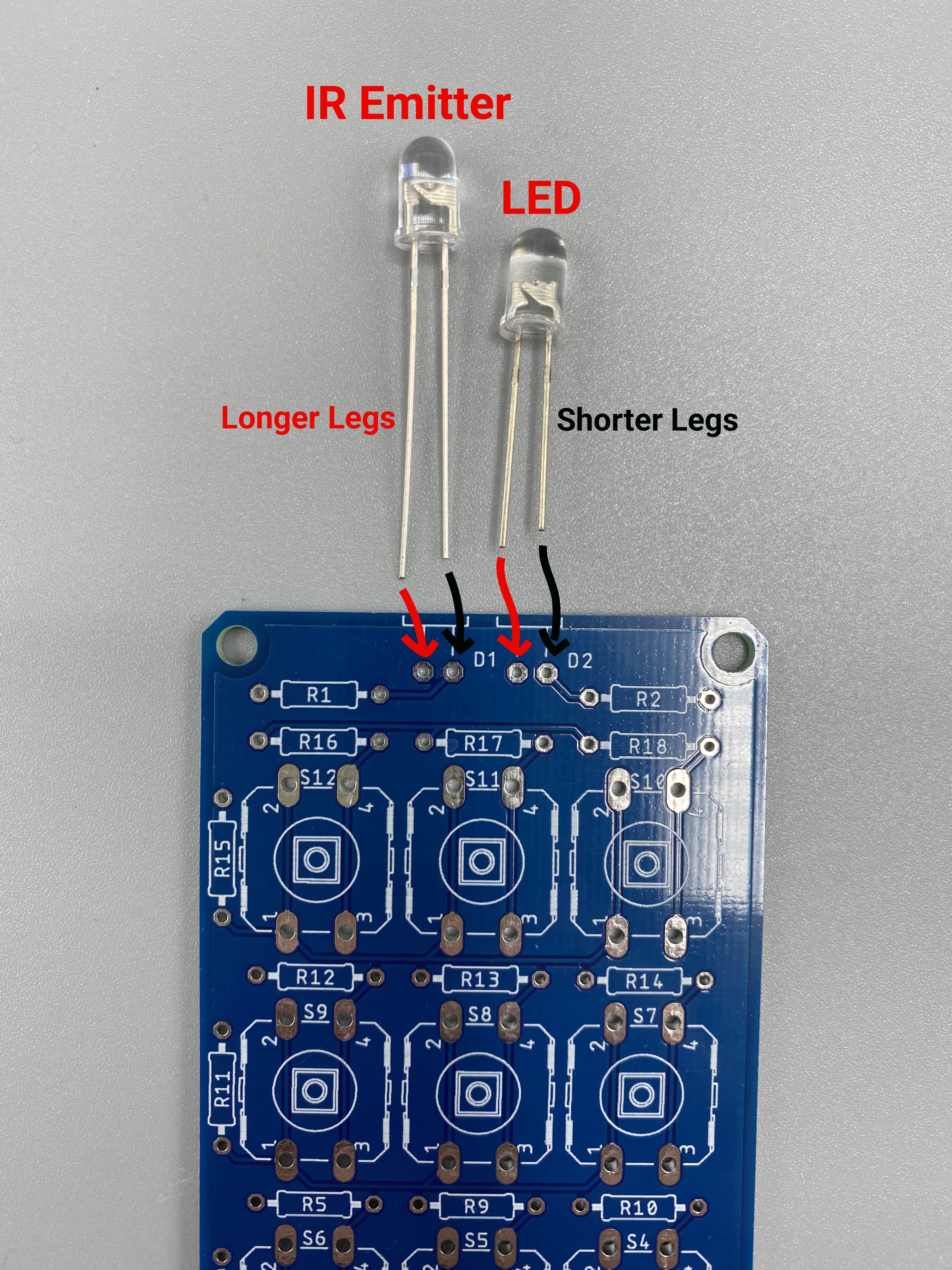
Solder the two LEDs.
The LED with the longer legs is the infrared LED and goes onto D1. The other normal LED goes onto D2
For each LED placement, the shorter pin on the LED goes into the right hole and the longer pin goes into the left hole
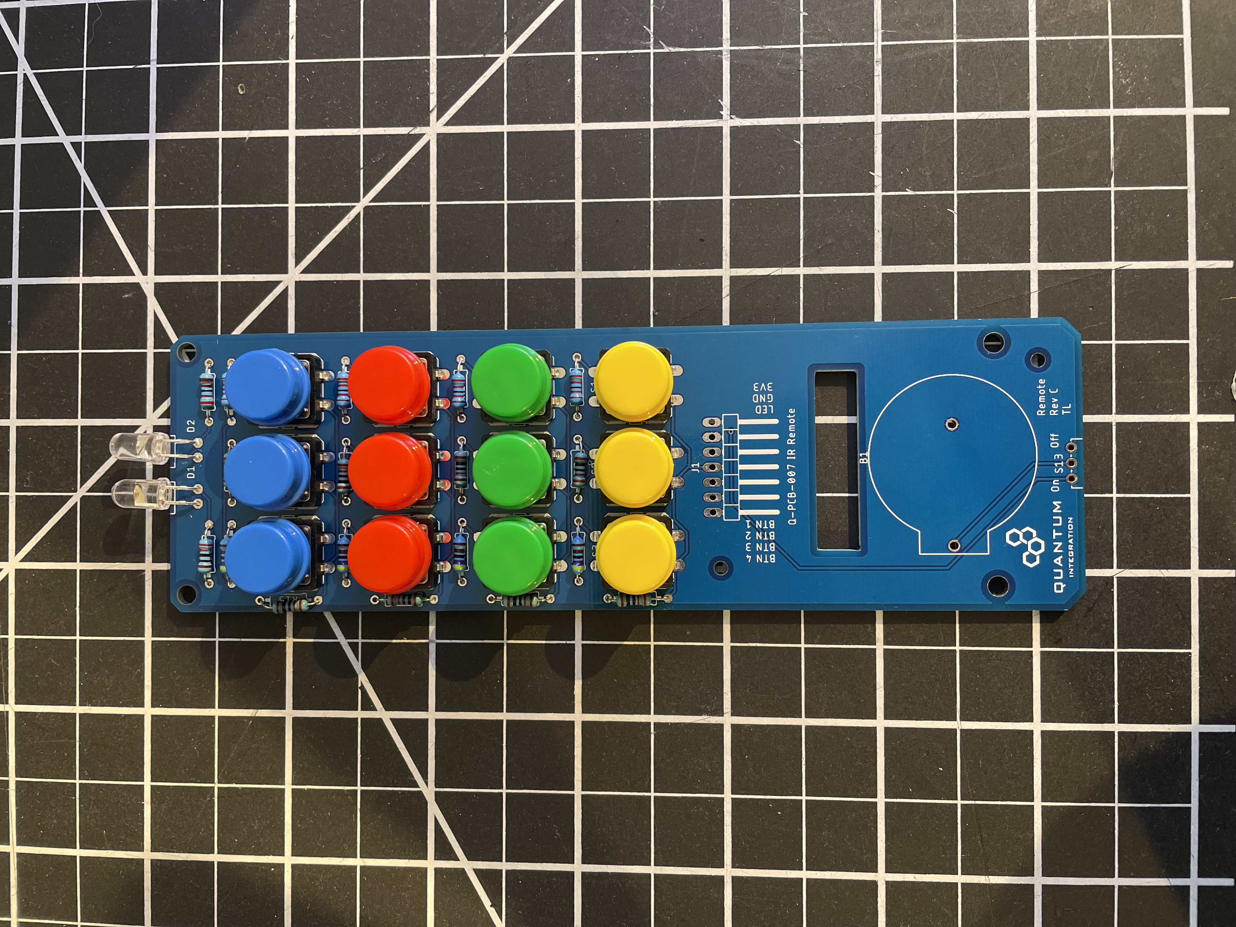
Solder the buttons on the dedicated schematics of the PCB. You can choose different color options but we recommend to use the same color for one row to have a better overview.
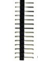
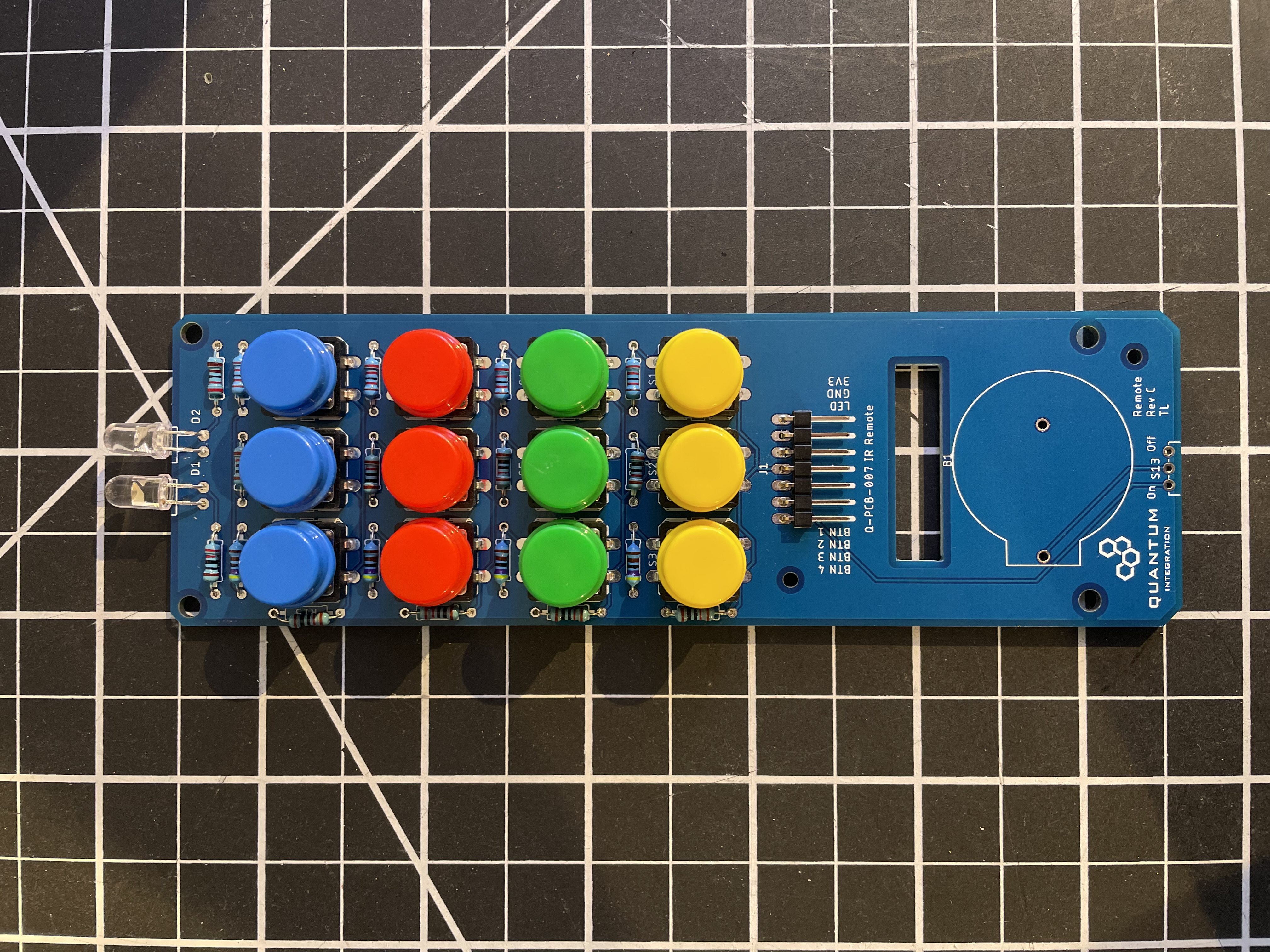
Solder the pin headers. Make sure they face to the hole of the PCB. This is were the wires will come trough.
Now we solder the switch. Make sure it faces away from the PCB.

Solder the battery holder.
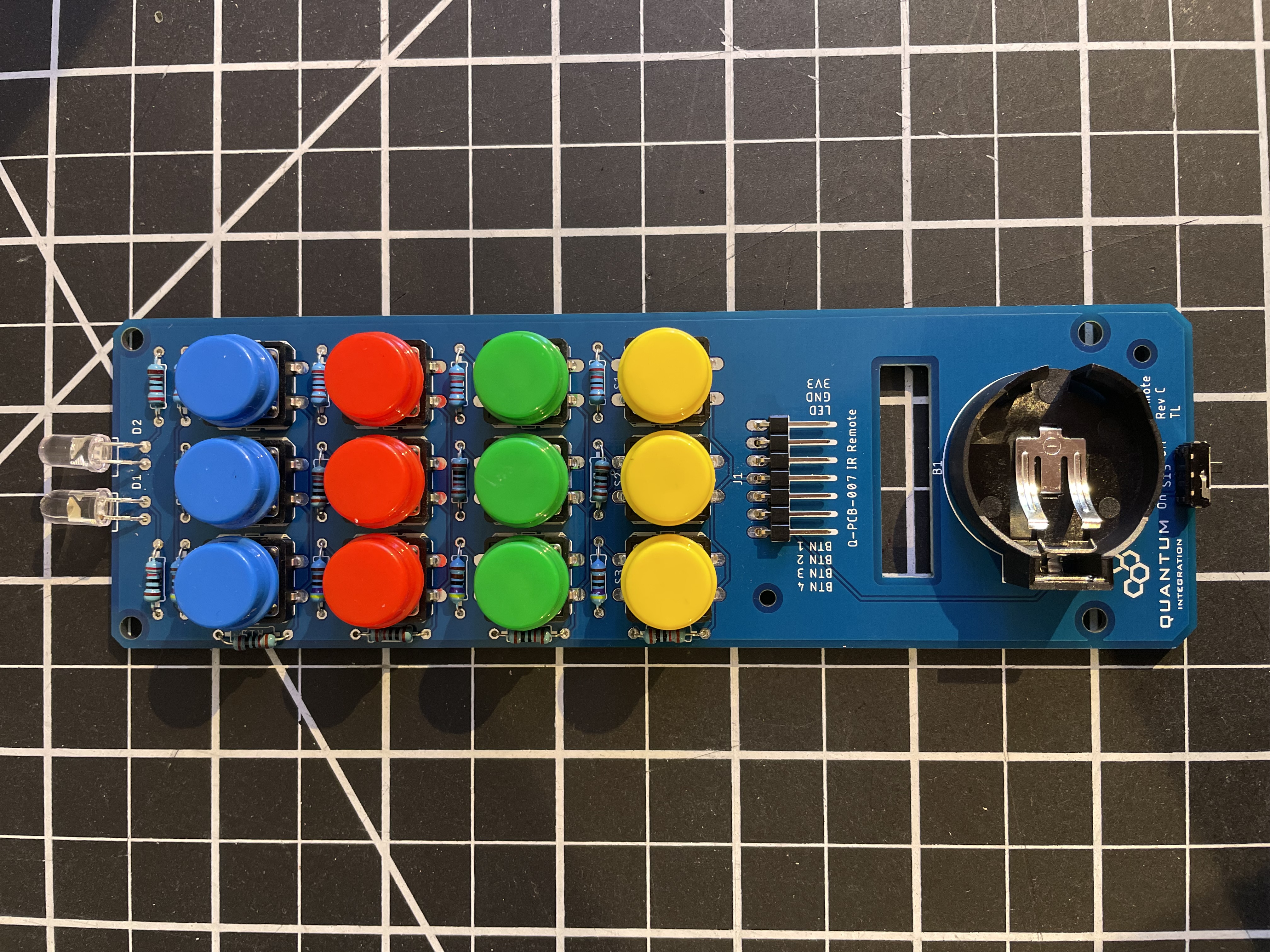
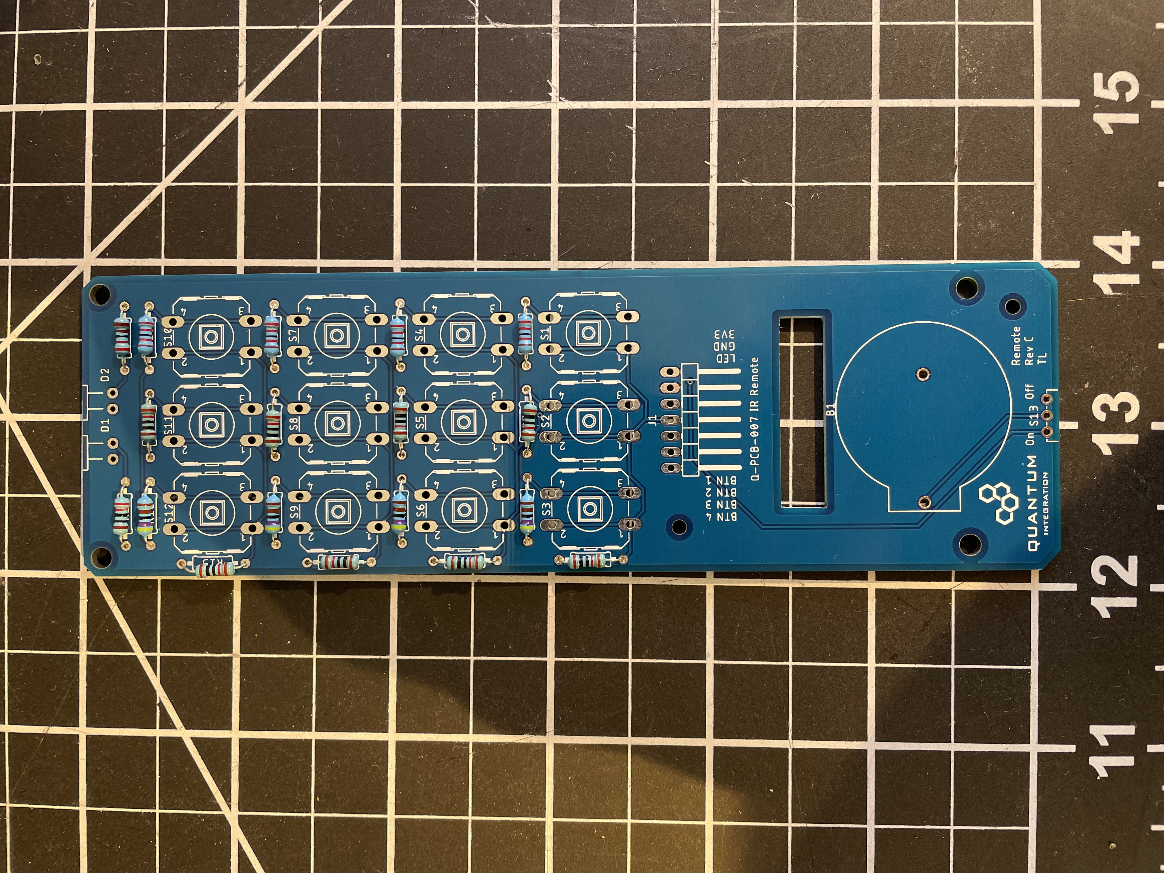
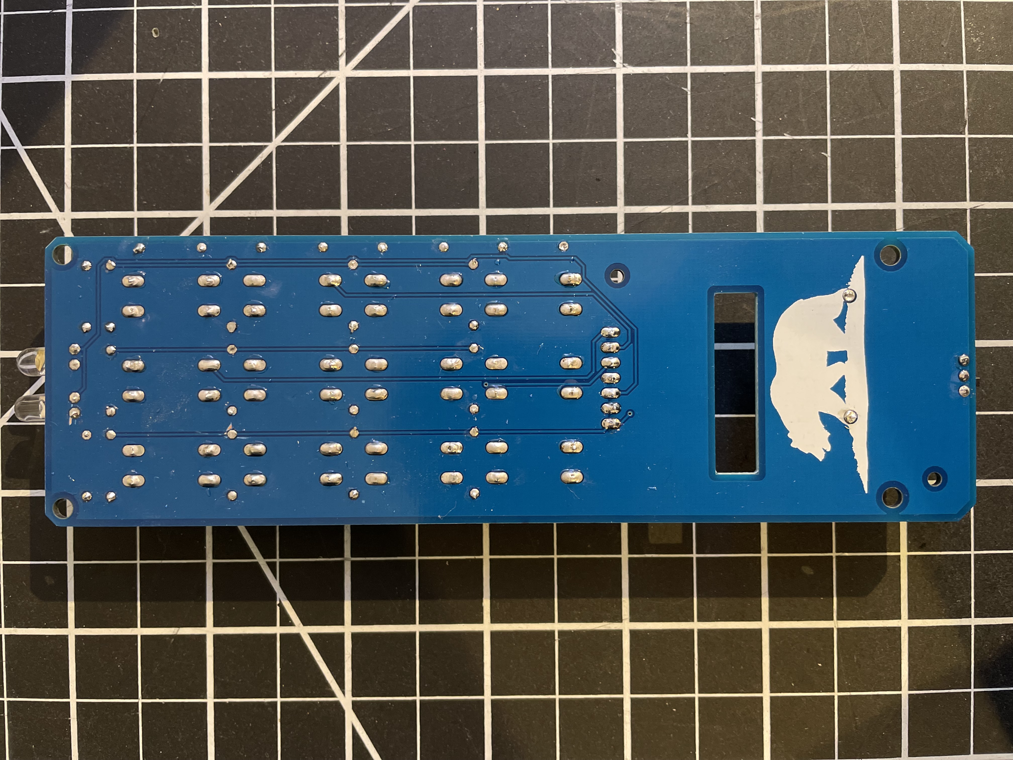
Your IR Remote is now ready to be used! The back should look like this.
Connecting to the Builder Base
Please refer to the following image on how to connect the DIY Kit to your Builder Base.
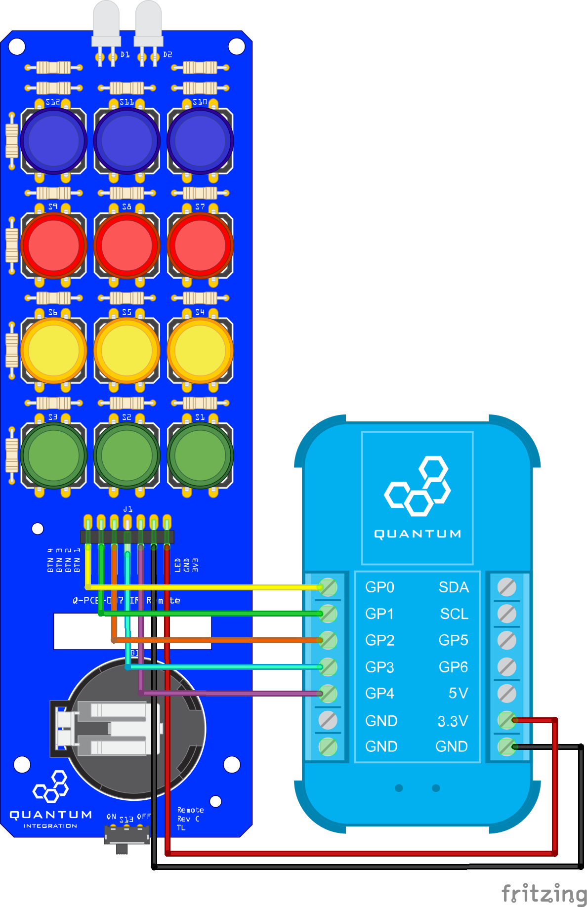
If your IR Remote has a different layout of the connectors you can’t use our firmware because the relation is through the button layout, its color and the position of it.
Multiplexing
This DIY Kit uses multiplexing technology. Multiplexing is a method by which multiple analog or digital signals are combined into one signal over a shared medium. The idea behind this is to reduce the amount of connections to a receiver by combining several signals at several distinct value ranges into a single medium.
In the case of the IR Remote, multiplexing is used to distinguish a series of push buttons based on the analog value that is received. So instead of having a single GPIO for each of the 12 push buttons we were able to reduce the amount of GPIO terminals used to one per row by determining the different analog values given by each push button in a series. The different analog values come from different resistor values of each push button.
Build the Firmware
Head to the Firmware tab of your Q-Server and click on “+ Create New” to start a new firmware file.
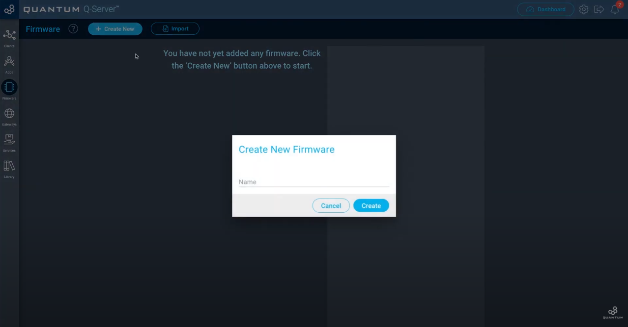
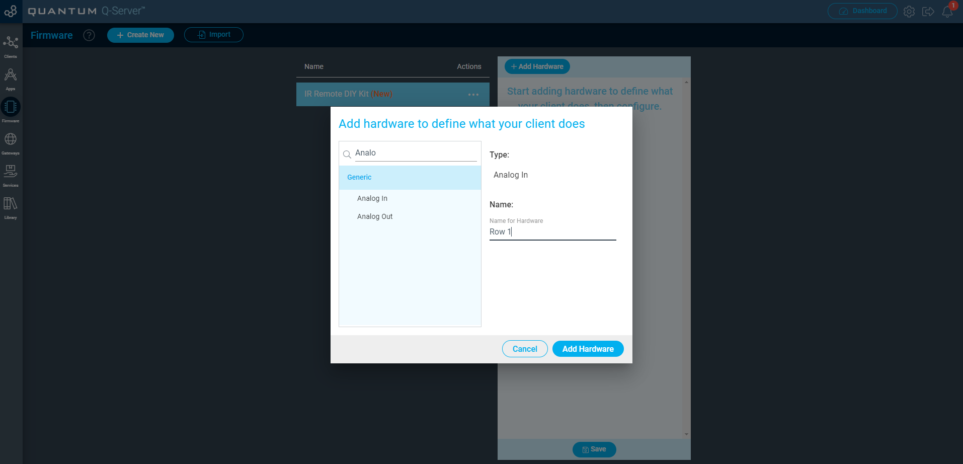
Give it a name so you remember your files. We named it “IR Remote DIY Kit”. Once you finished that we can add hardware to our firmware file. Simply click on the IR Remote firmware and then on “+ Add Hardware”.
So since we are using multiplexing for this DIY Kit to reduce the amount of GPIO terminals we need to use, we’re not going to be adding button hardware. Instead we will use one Analog In hardware for each row of the DIY Kit.
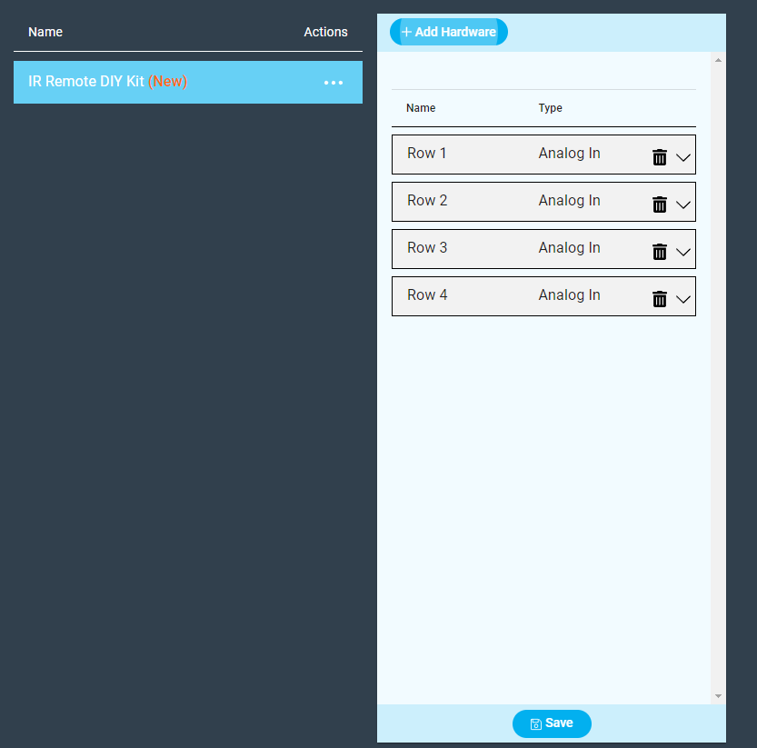
Add four of those. We name them Row 1, Row 2, Row 3 and Row 4.
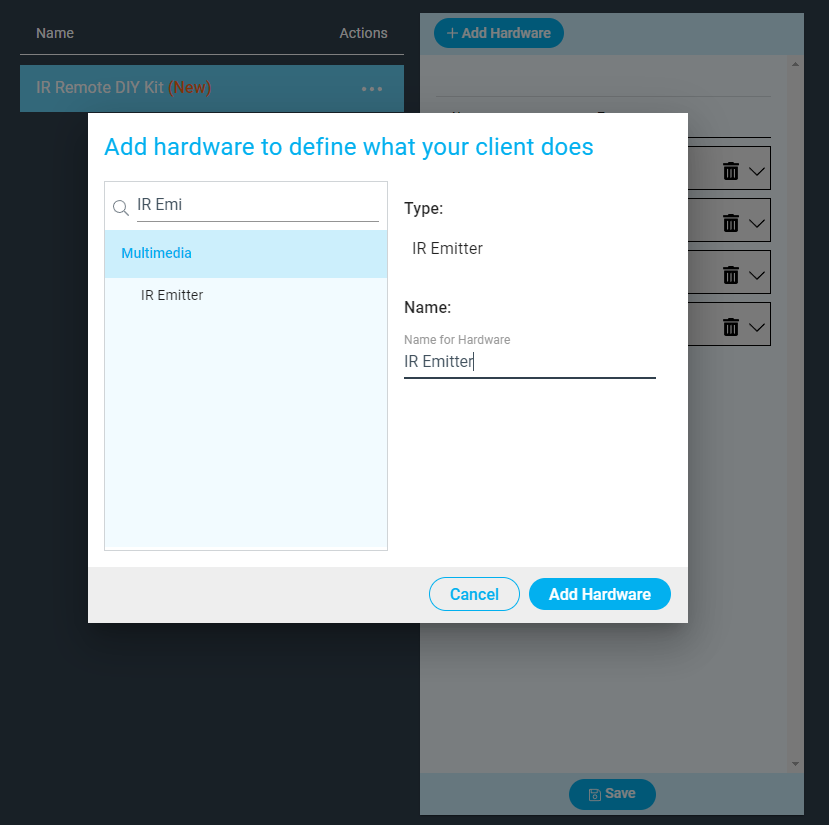
Lastly we will have to add the LED hardware. Both the indicator LED and the IR Emitter LED are on the same GPIO terminal. We add one IR Emitter hardware for that.
The next step is to assign these different types of hardware to certain drivers and GPIO terminals they’re being used.
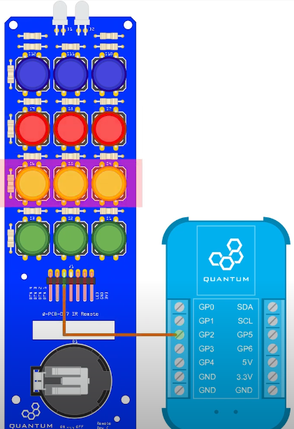
For Row 1 we select GPIO as the Driver and for the pin GP0. Select the terminal which is connected to the pin that says “Button 4” on your IR Remote.
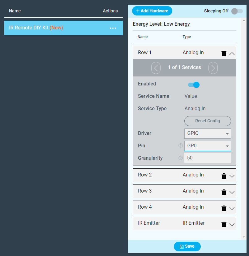
For Row 2 use the same Driver and the Pin is GP1 or select the terminal that is connected to the pin that says “Button 3” on your IR Remote.
For Row 3 use the same Driver and the pin GP2 or select the terminal that is connected to the pin that says “Button 2”.
For Row 4 use the same Driver and the pin GP3 or select the terminal that is connected to the pin that says “Button 1”.
For the IR Emitter select the IR Emitter as the Driver and then select the pin that is connected to the pin “LED” of the IR Remote. In our case it is GP4.
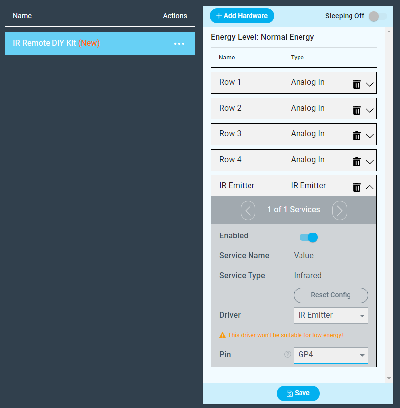
Lastly hit “Save” and upload the file to the Builder Base that is connected to the IR Remote.
Build the App
Demo
Resources
App & Firmware
This DIY Kit page is currently optimized for revision C.
Current revision
Assembly files for the current revision of the DIY Kit (Rev C): | https://github.com/QuantumIntegration/Q-PCB-007-IR-Remote-Hardware-Files |
|---|
Older revisions
- | - |
|---|