| Table of Contents |
|---|
Introduction
The 4x3 button keypad driver can connect buttons from a generic 4x3 keypad to the Builder Base. The driver represents a single button on the keypad. This way a desired amount of buttons or the entire keypad can be added to the system.ACS712 current driver measures mA (Milliamps).
Tim Lubes (Unlicensed) please improve
Driver Parameters
The GPIO ACS712 driver for Digital Inputs has two three parameters that have to be configured:
Row Pin
This is the pin connected to the row of the button we want to read. There are 4 rows above each other and the most left pin is representing the top row
Column Pin
This is the pin connected to the column of the button we want to read. There are 3 columns next to each other and the 5th pin from the left is representing the most left columnPin
Tim Lubes (Unlicensed) please describe
Resolution (mA)
Tim Lubes (Unlicensed) please describe
ACS Model
Tim Lubes (Unlicensed) please describe
Wiring
The wiring of the ACS712 can be found below:
Example
The top row is connected to GP0 and the most left column is connected to the GP1. With this setup we would read the state of the “1“ button.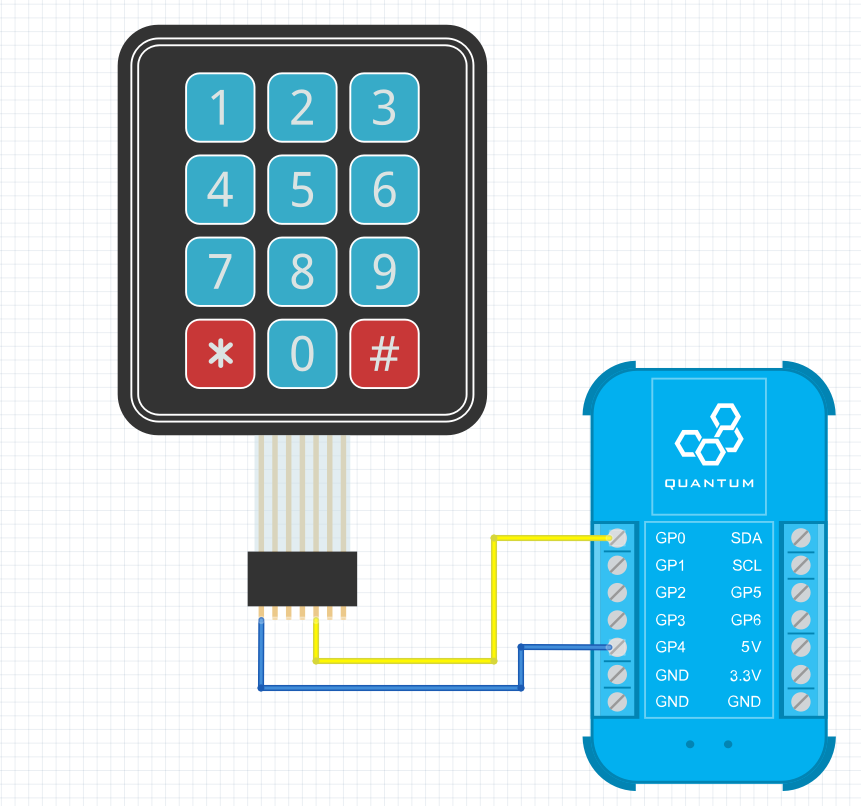
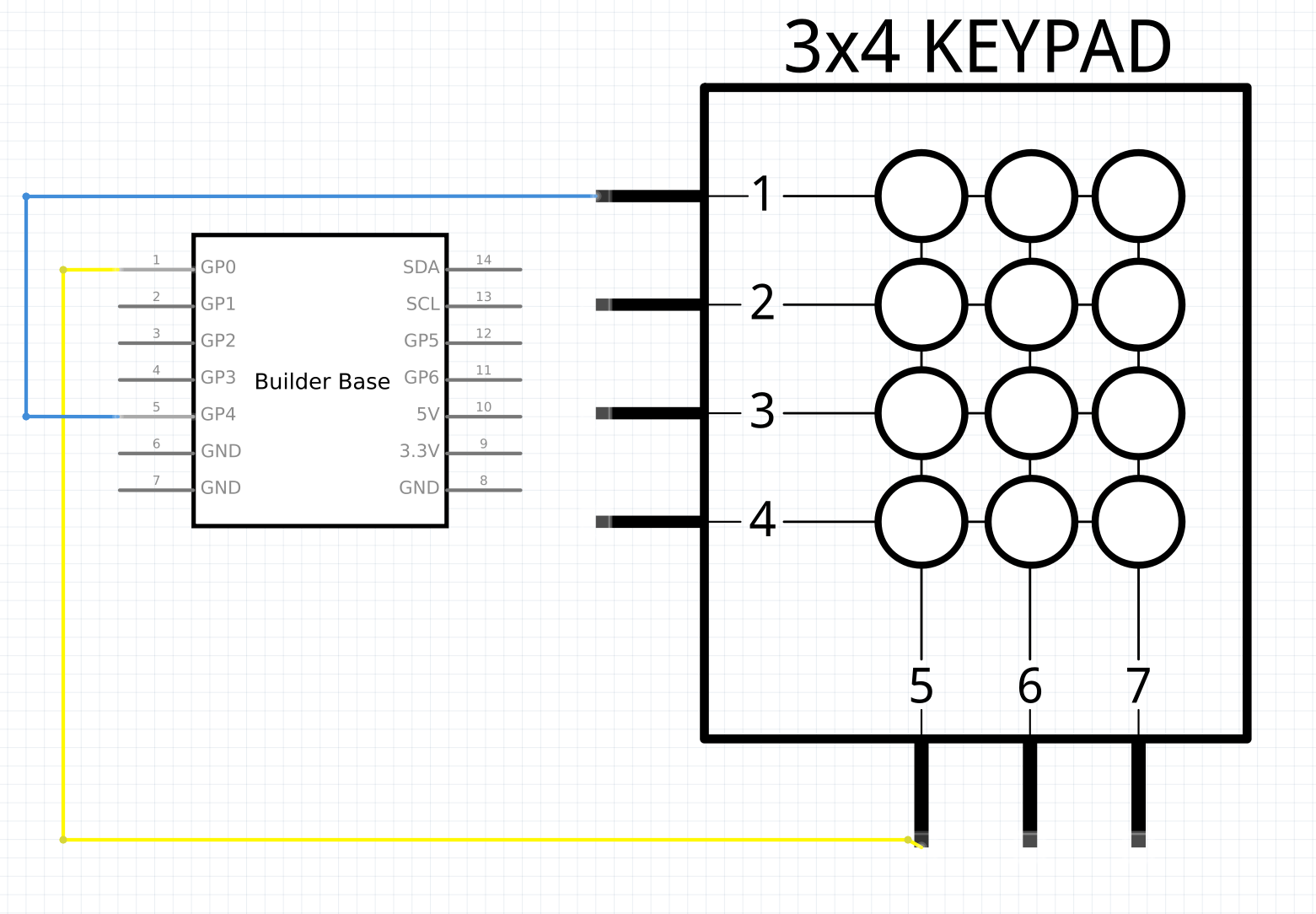
Used Pins
Used Pins | Description |
|---|---|
GP4 (can be any GP pin) | This pin is connected to the row of the button we want to read |
GP0 (can be any GP pin) | This pin is connected to the column of the button we want to read |
Tim Lubes (Unlicensed) please add | Tim Lubes (Unlicensed) please add |
How to write an App
Navigate to the App Builder and create a new application. You can find the “Digital Out” code “Current” hardware object under the “Hardware” Tab in the object drop down menu on the left, or you can also use the search bar.
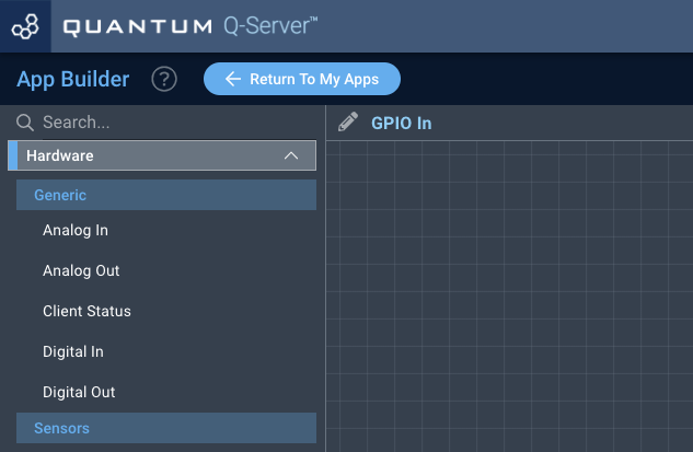
Drag the “Digital Out” “Current” Object onto the canvas. We also need a “4x3 keypad” “Text” interface object.
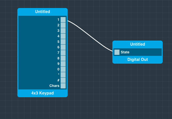
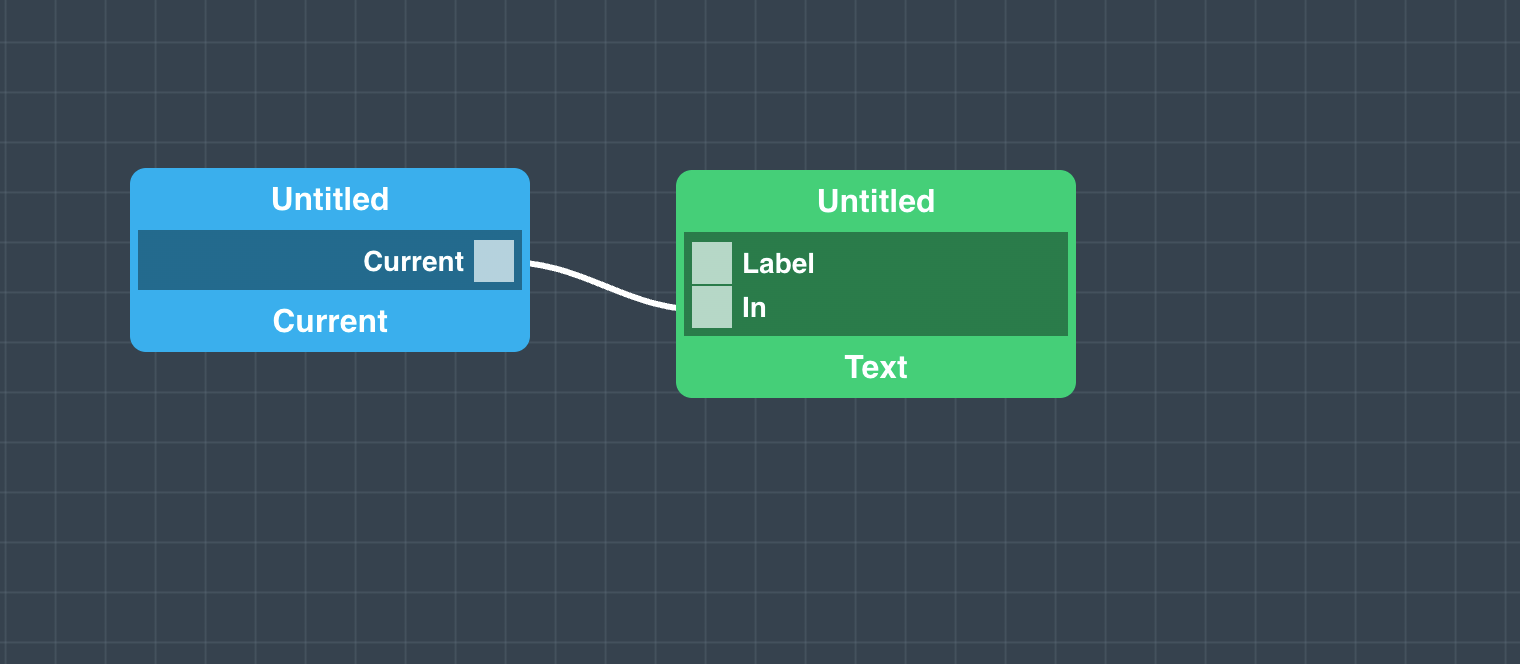
Connect the “1” of the “4x3 Keypad” object with the “State” port of the “Digital Out”“Current“ Port to the “In“ Port of the Text Interface Object. We can now see the state of the button which means that we see wether the “1” of the keypad is pressed or notmA measurement of the sensor in our text field on the dashboard.
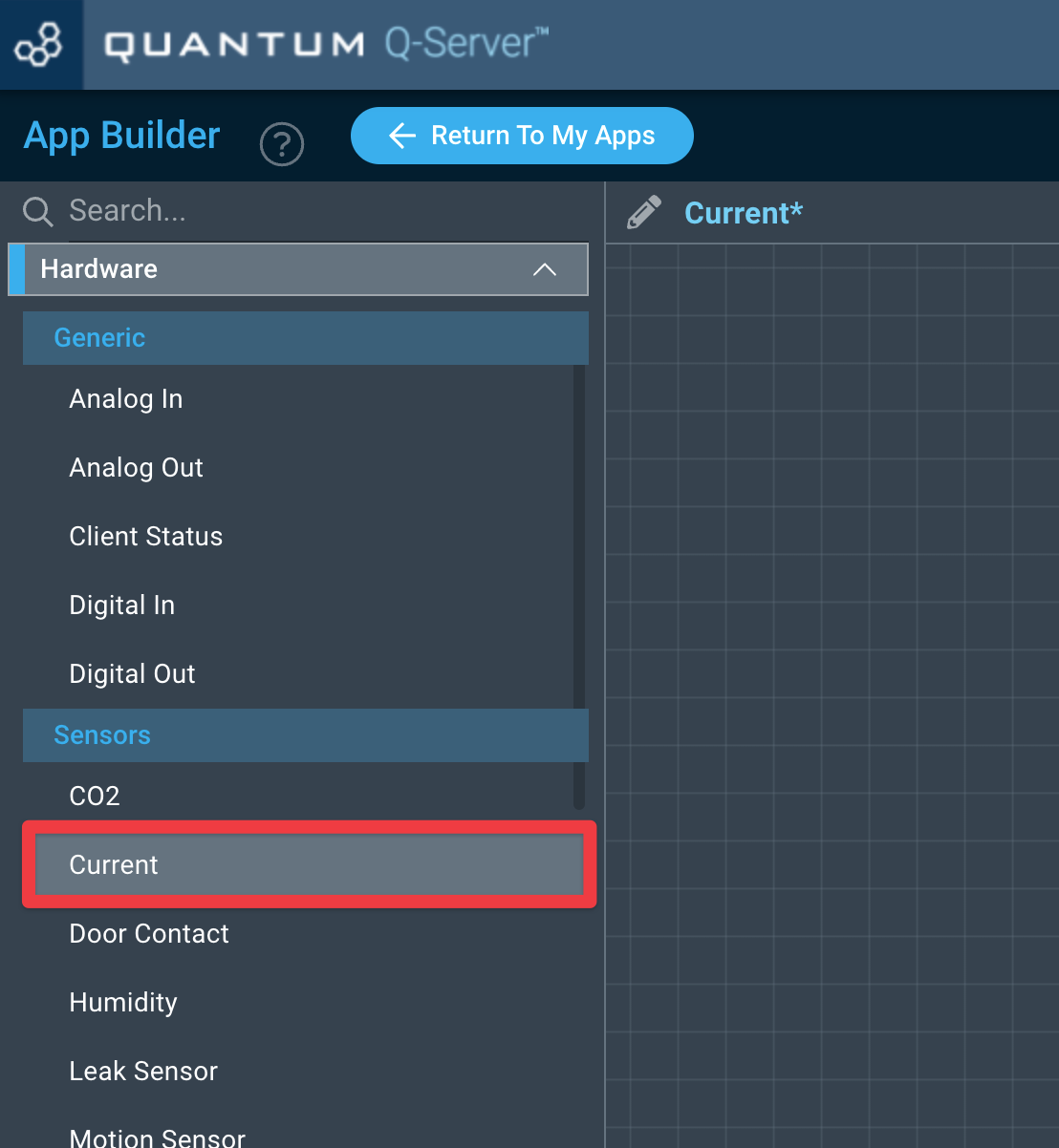
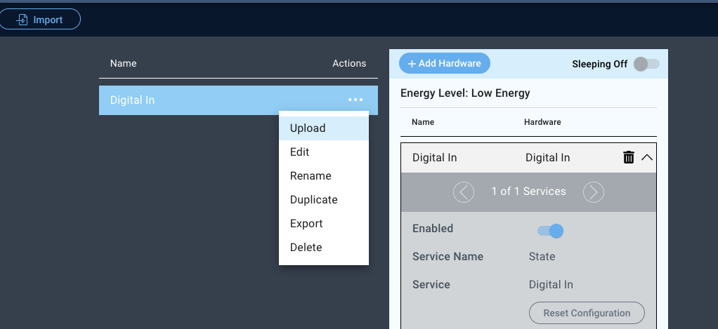
How to create a firmware
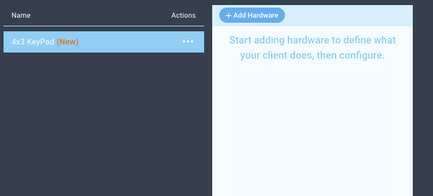
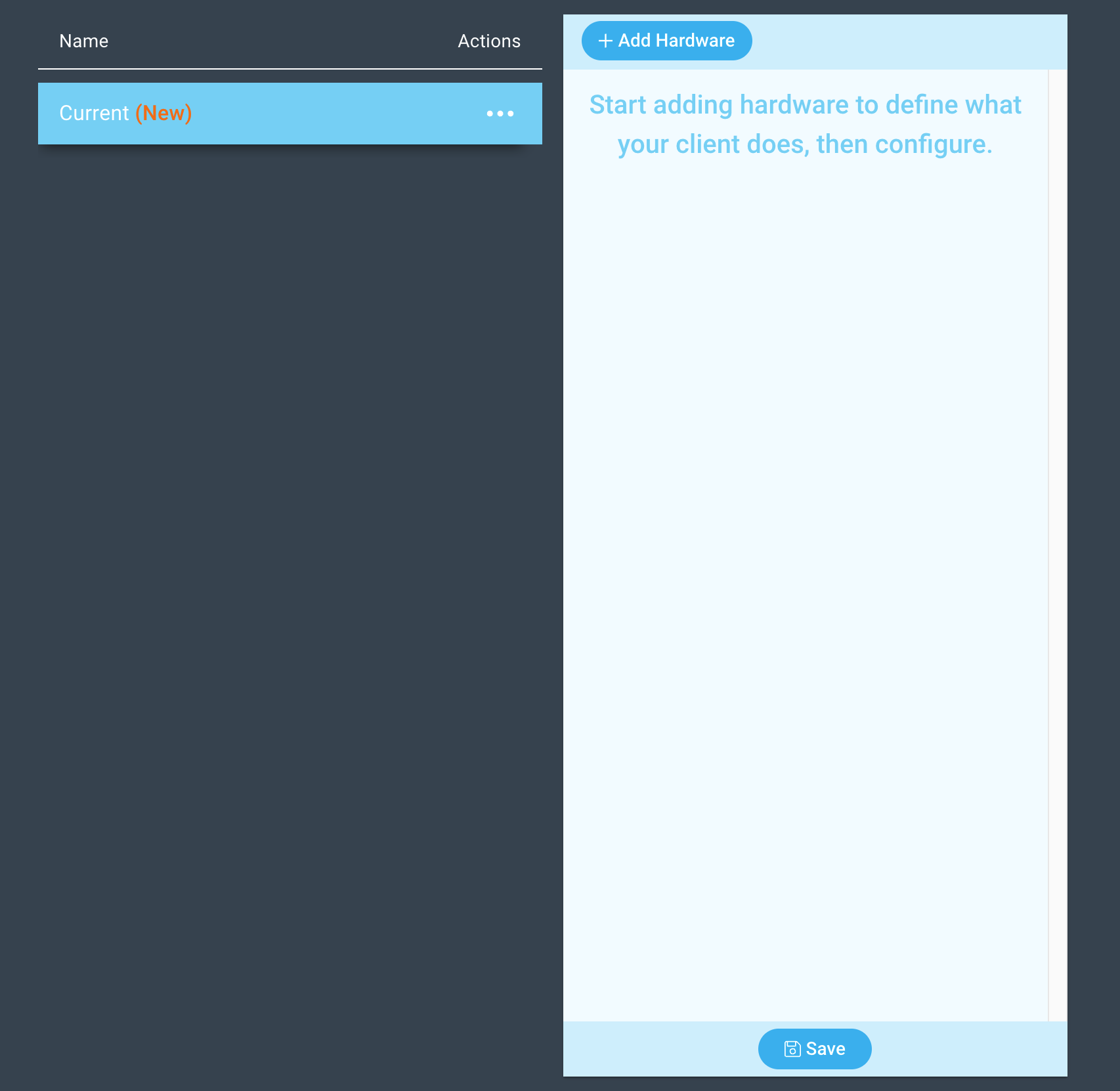
Navigate to the Firmware Builder and create a new firmware file.
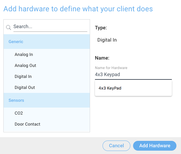
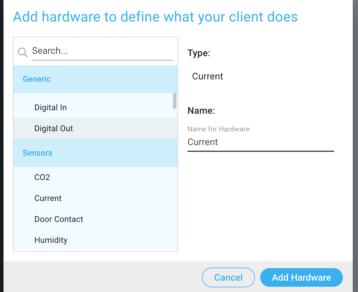
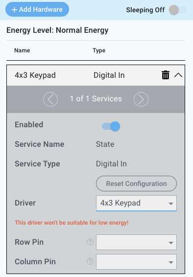
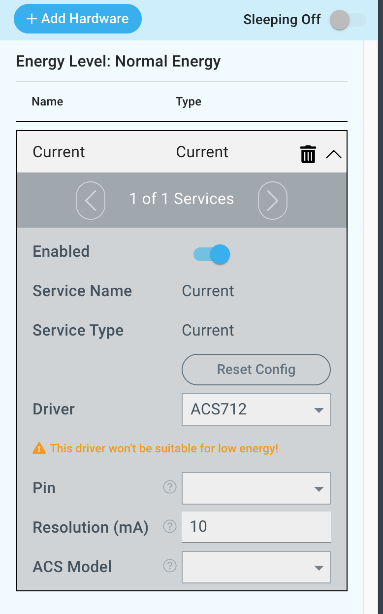
Click the “+ Add Hardware” button which will open a modal window. Scroll down in the list to find the “Generic” “Sensor” section and select the “Digital In” “Current” hardware option.
Give your device a name, and click “Add Device”
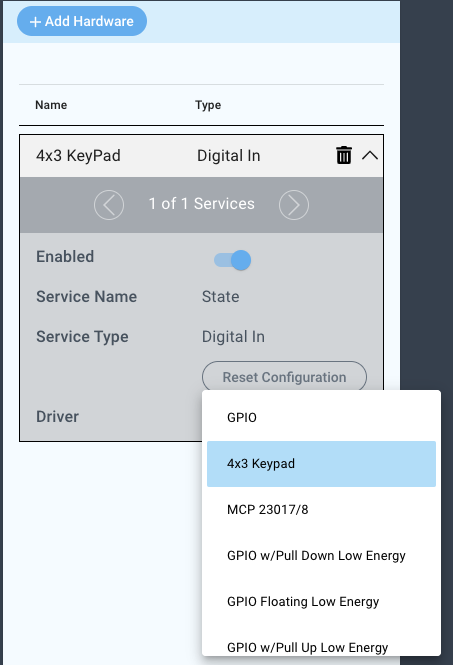
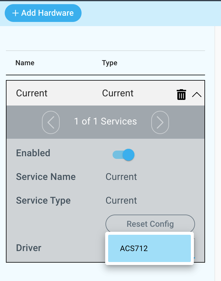
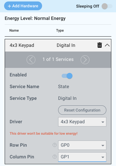
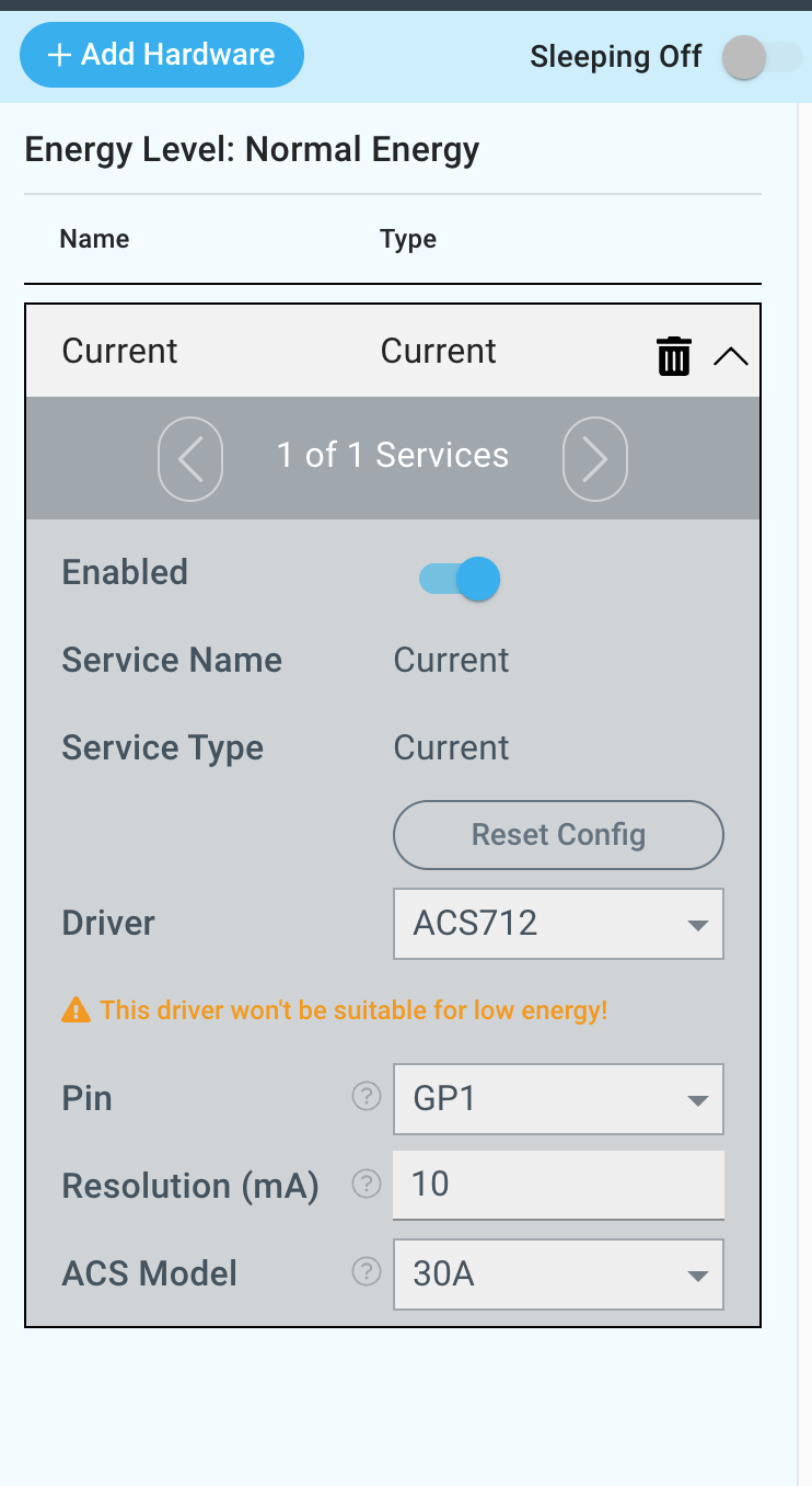
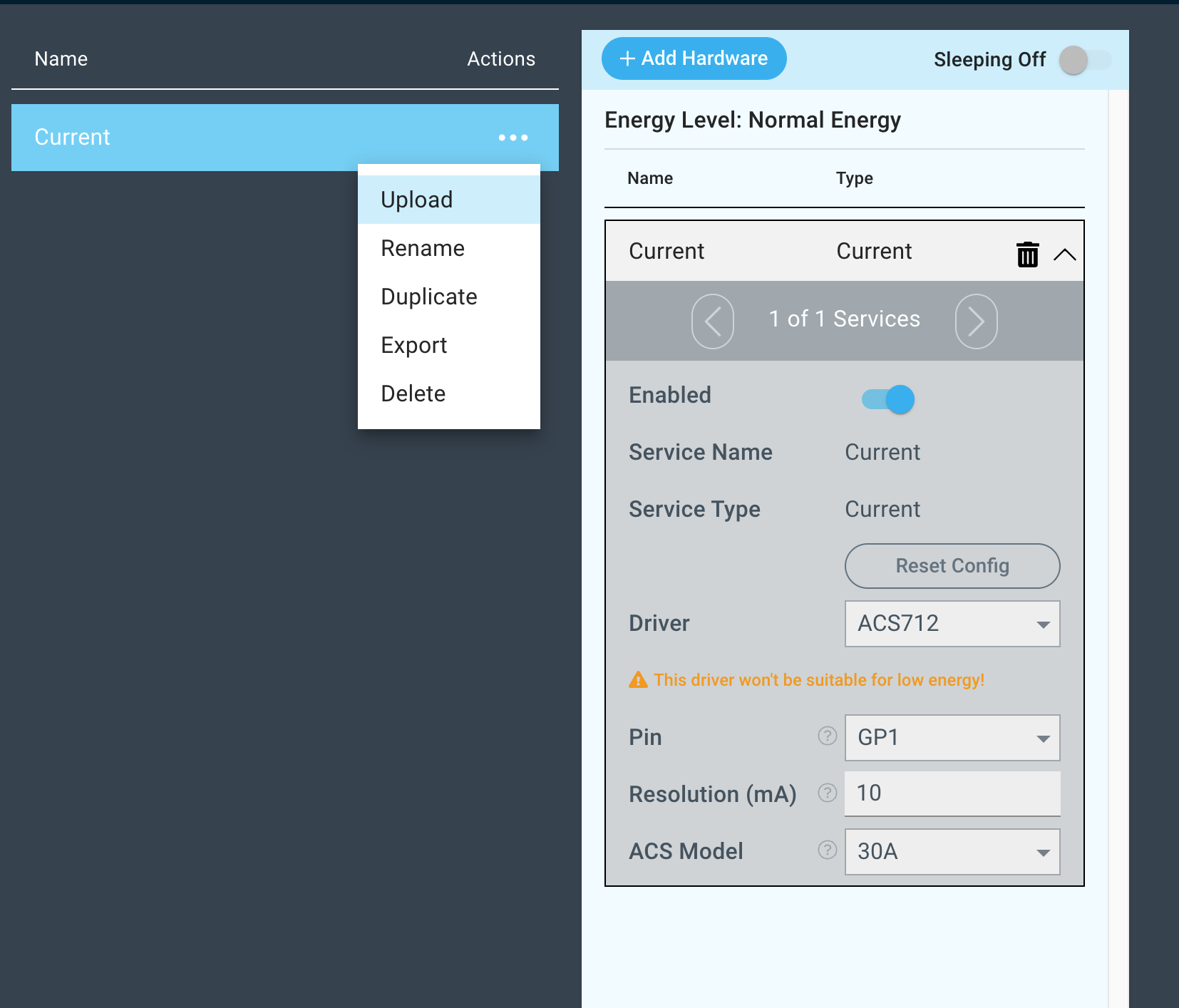
Next, select the “4x3 Keypad” “ACS712” driver under the driver dropdown menu, set the Row Pin and the Column Pin, Resolution and ACS Model.
For this example we select:
Row Pin: GP0
Column Pin: GP1
GP1
Resolution (mA): 10
ACS Model: 30A
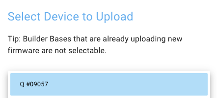
You may now save your firmware file and upload it to one of your clients.
Supported Hardware
Current
Downloads
Apps
| View file | ||
|---|---|---|
|
Firmware
| View file | ||
|---|---|---|
|
Assets
Assets
Tim Lubes (Unlicensed) please add