| Table of Contents |
|---|
Overview
| Widget Connector | ||||||||||
|---|---|---|---|---|---|---|---|---|---|---|
|
| Info |
|---|
For Fullscreen: https://www.youtube.com/watch?v=4bm6Bz-xAJ4 |
This project is intended to show one how to setup a joystick with their Quantum platform. The joystick prototype consists of two joysticks and a button. It can be wired up on a breadboard using the schematics. The joystick can be used for controlling the Mecanum car or steering car.
You can also build this project with one of our DIY Kits!
Check out the Joystick DIY Kit page to find out how.
|
|
|
|


Hardware Components
Picture | Name | Quantity | Link |
|---|---|---|---|
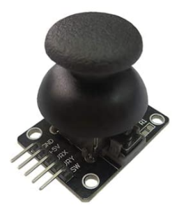 | Joystick | 2 | One is included in the Component Kit, but you can purchase the second one here |
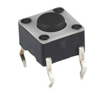 | Tactile Push Button | 1 | Included in Component Kit Or you can purchase it here |
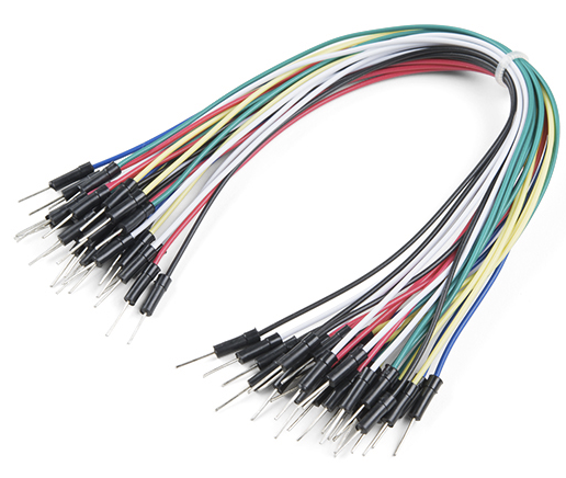 | Jumper Cables (MM) | 4 | Included in Component Kit Or you can purchase it here |
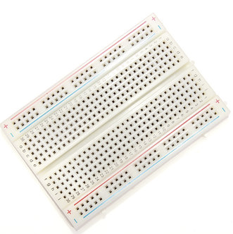 | Breadboard (any size) | 2 | Included in Component Kit Or you can purchase it here |
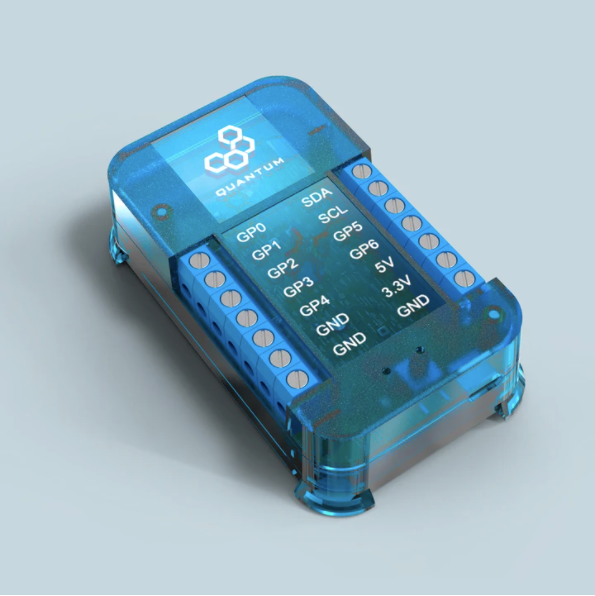 | Q-Client Builder Base | 1 |
Tools Used
Picture | Name | Quantity | Link |
|---|---|---|---|
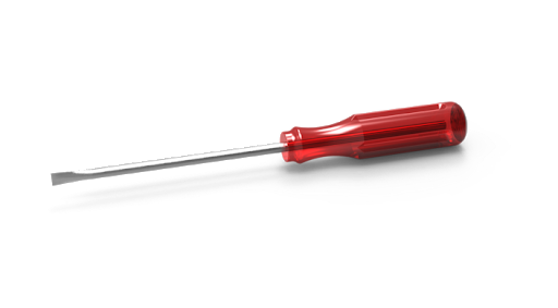 | Small flat-head screwdriver | 1 | Included in the Component Kit or you can pick from one on our Recommended Tools List |
Assemble the Circuit
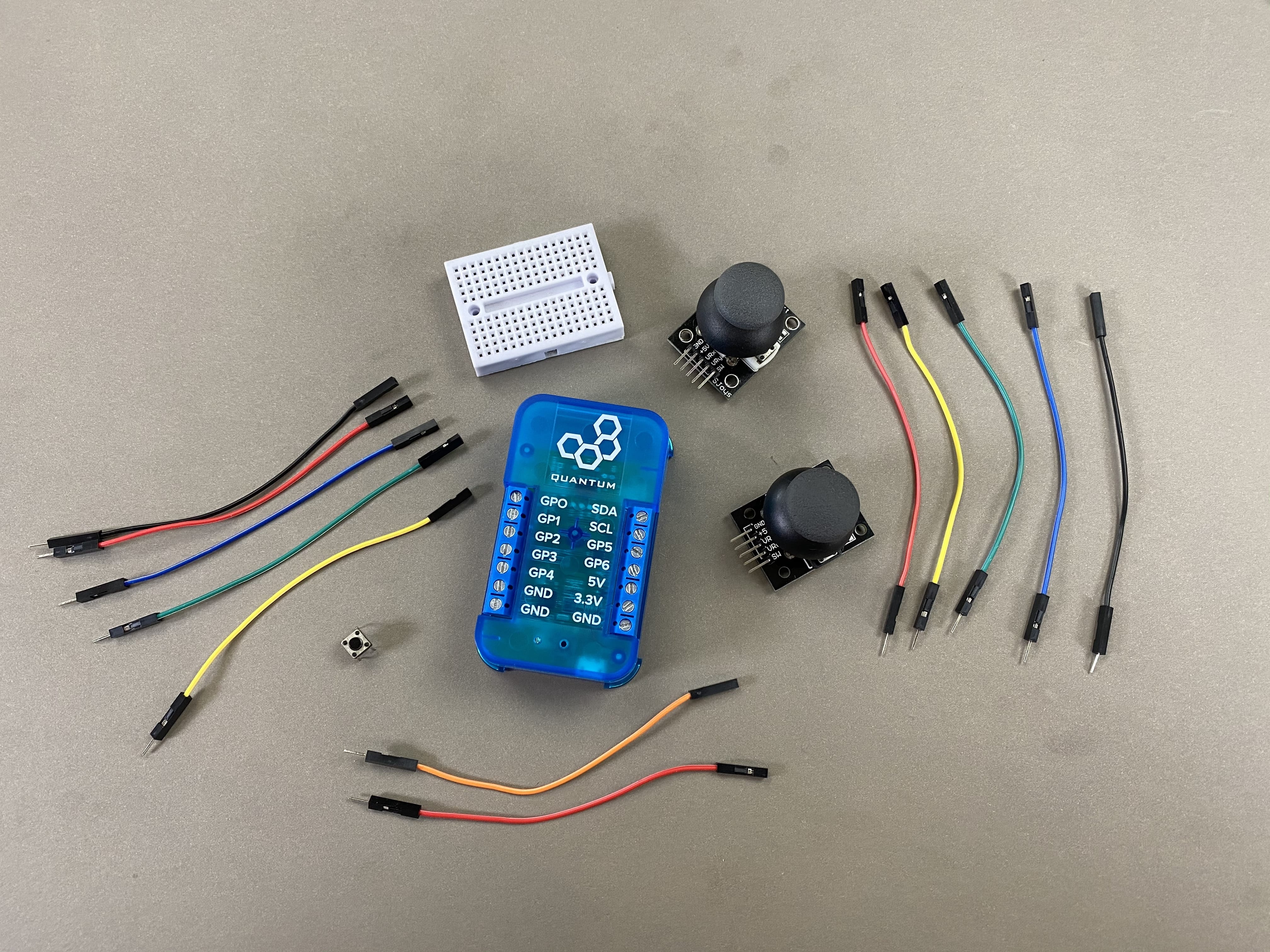
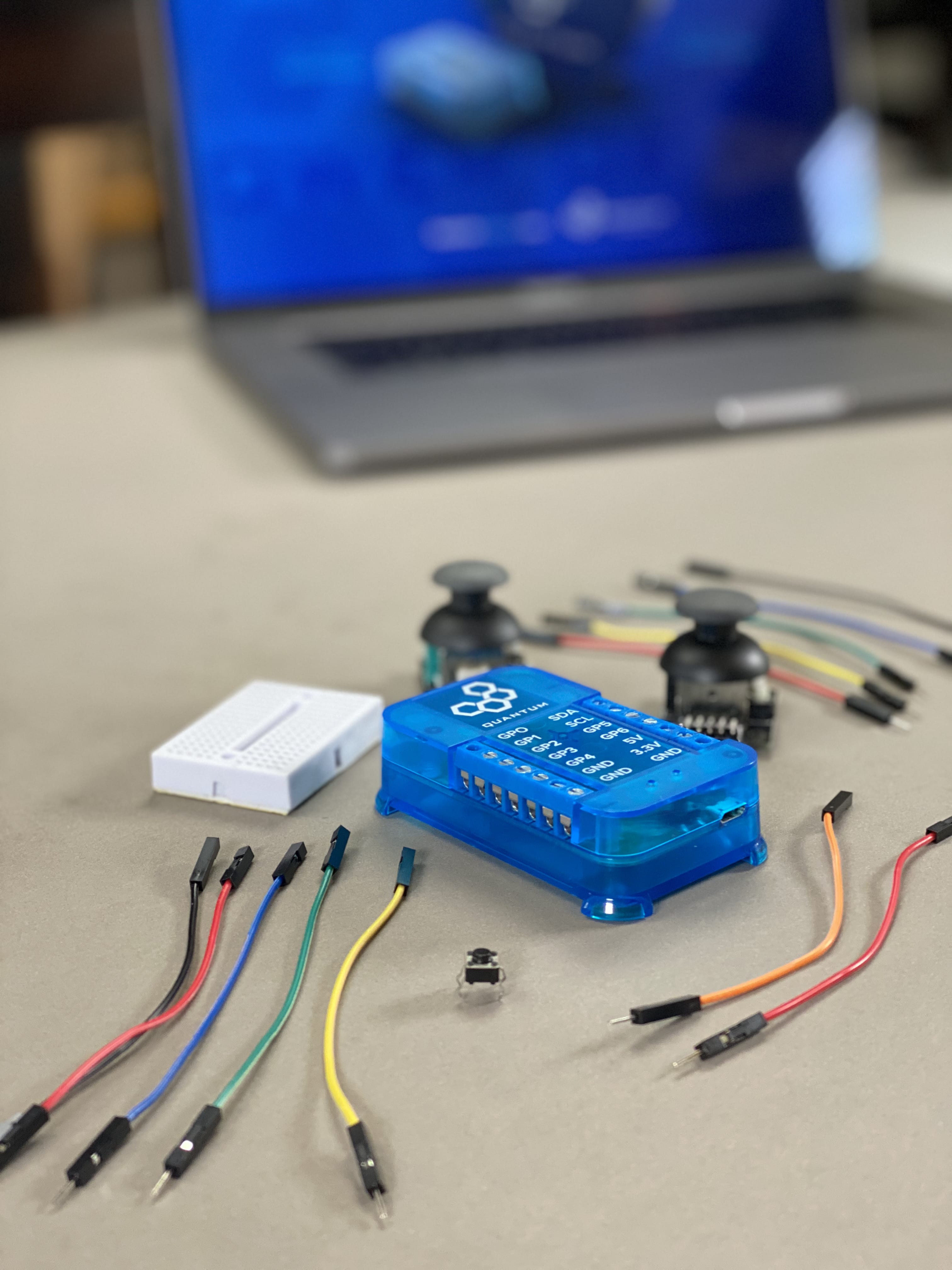
To get started, gather all of the parts listed above.
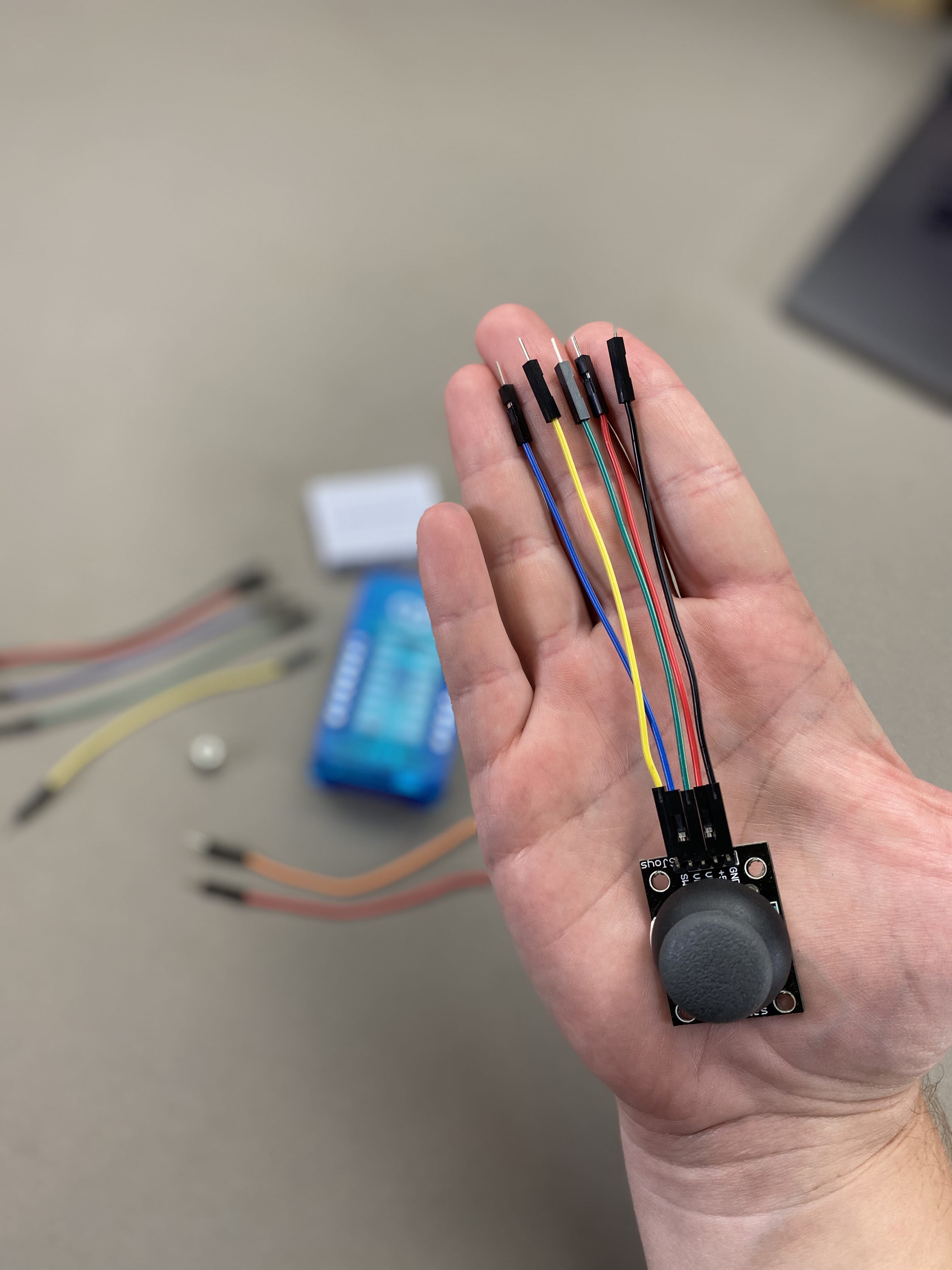
Take your two joysticks and connect a male to female jumper wire to every terminal on them. Like so:

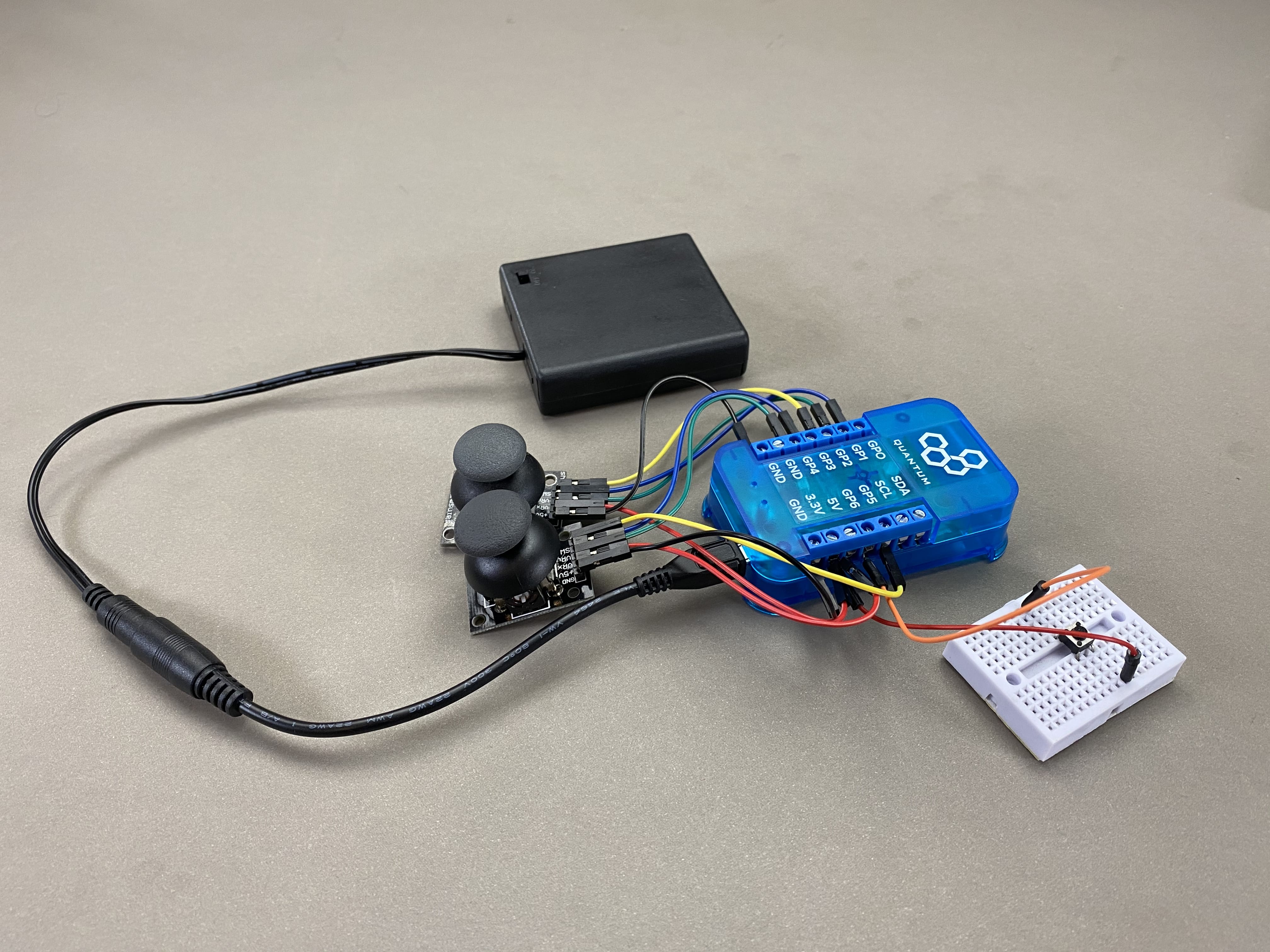
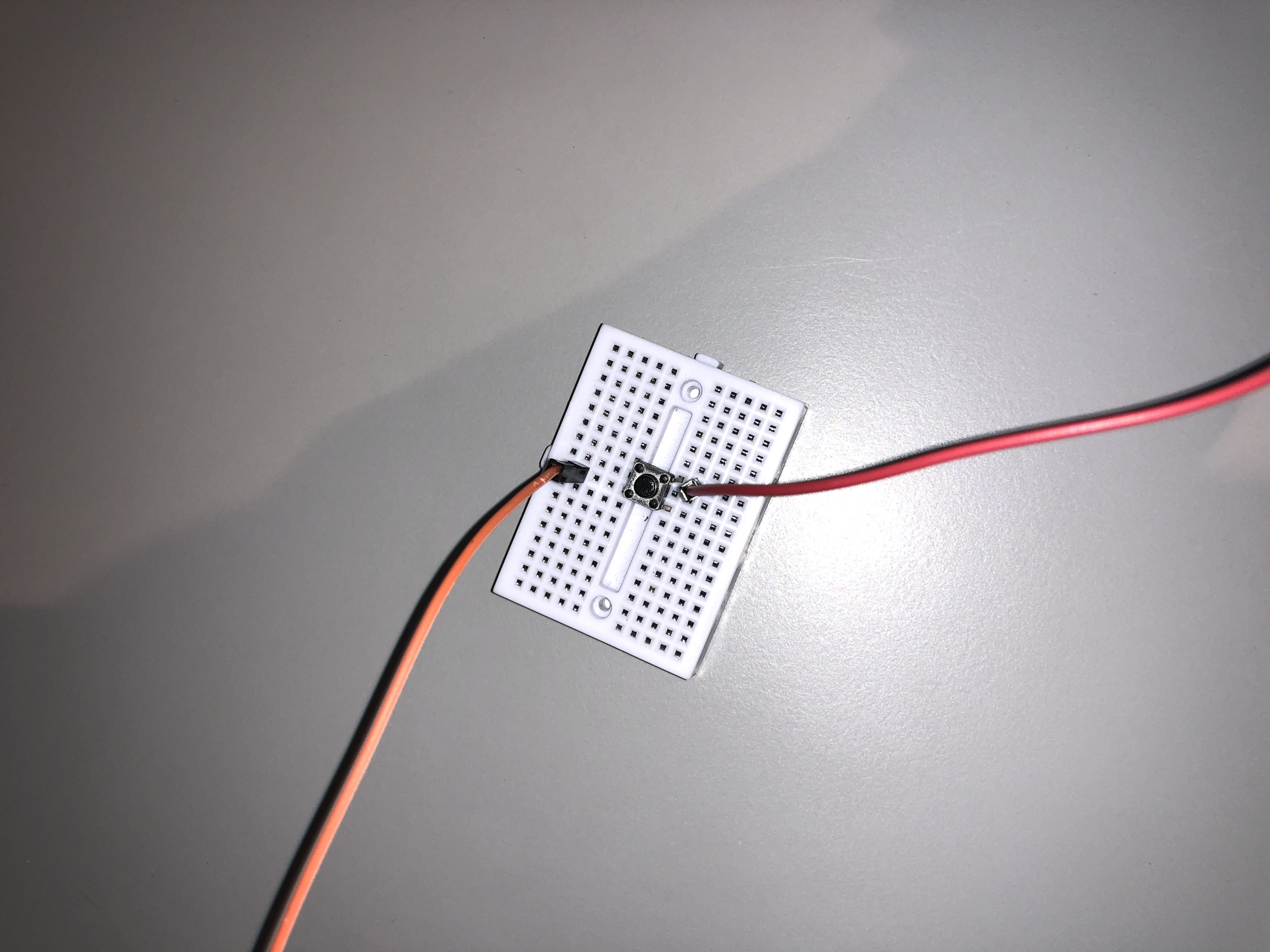
Now, on your bread board place the tactile push button and attach a MM jumper wire to one pin and another MM wire to the pin diagonal to that one, like so:

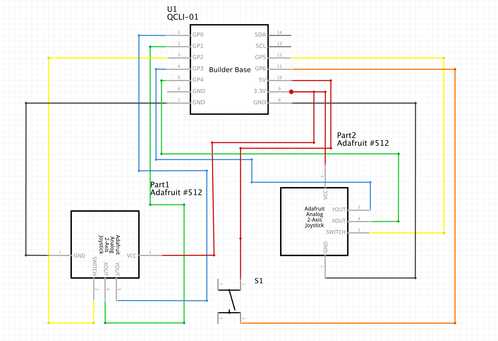
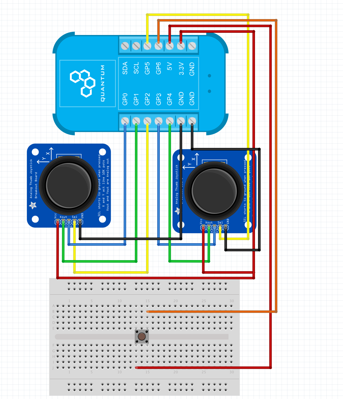
Finally, follow the schematic and bread board diagrams below to attach the components to the Builder Base:
.png?version=3&modificationDate=1619170032219&cacheVersion=1&api=v2)
.png?version=3&modificationDate=1619170032241&cacheVersion=1&api=v2)
| Note |
|---|
Be careful to connect both Joysticks to 3.3V and not 5V! If you don’t your readings will be wrong. |
Pair the Builder Base
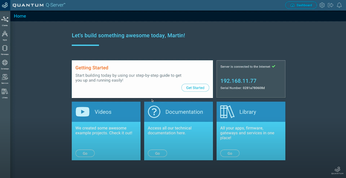
Now we want to pair the Builder Base with our Q-Server. In order to do so, go to the Homescreen of your Q-Server.
Next click on the lift side symbol labeled “Clients”. Switch to the “Unpaired” tab at the top middle of the screen.
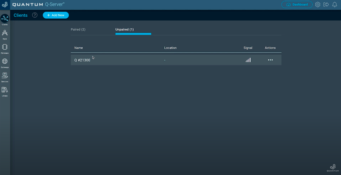
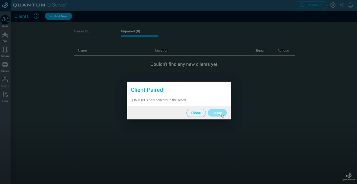
You should see your unpaired Builder Base. If not, check if you have plugged in the power supply for the Builder Base. Now move to the three dots below “Actions” and click “Pair”.
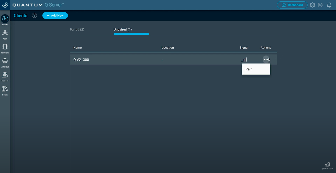
Once your Client is paired, click the “Setup” button.
Now you can edit your Client. Give him a Name you want and also a location where you are going to use it. Hit “Save” when you finished.
Build the Firmware
| Tip |
|---|
Remember: all Apps and Firmware files are available in the resources section below! |
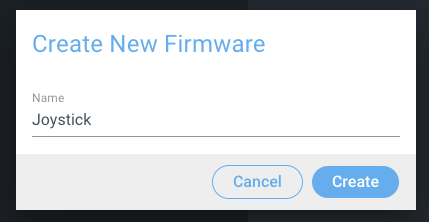
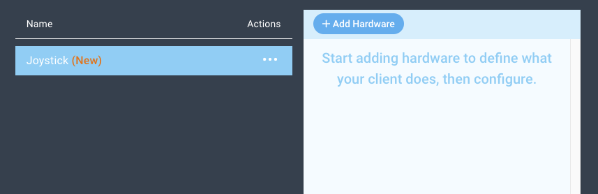
Navigate to the Firmware Builder and create a new Firmware file. We named ours Joystick.

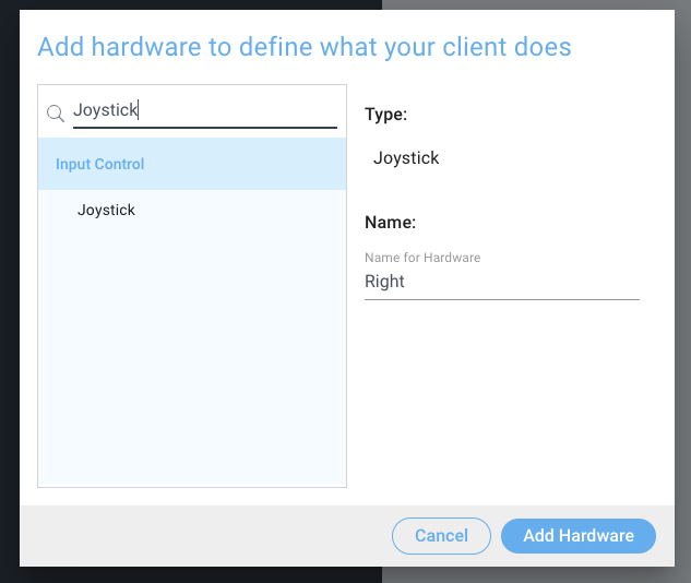
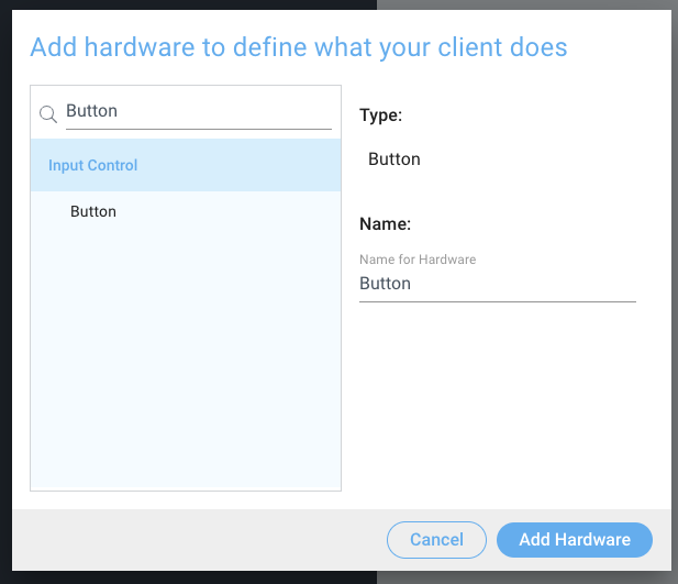
Next, click the “+ Add Hardware” button and find the Joystick device via the search bar, select it, name it, and then click “Add Hardware”. We named ours Left.

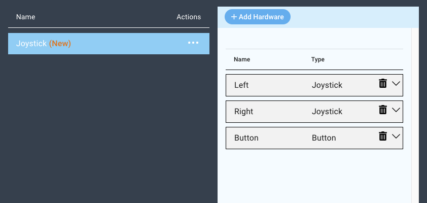
Now, add another device by clicking the “Add Hardware” button again, and add another Joystick. We named this one “Right”.

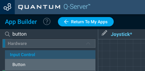
Lastly, we will add one more device. Repeat the steps above to add another device, but this time search for a “Button”.

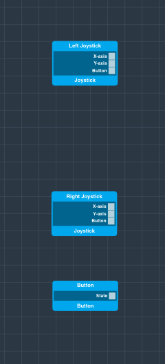
You should now have three devices in your firmware file.

Now you can follow this video to configure each device in the firmware file:
| Note |
|---|
Your joystick may come in a different pin mode configuration. Make sure to read manufacturer documentation on whether the joystick pushbutton is pull up or pull down. |
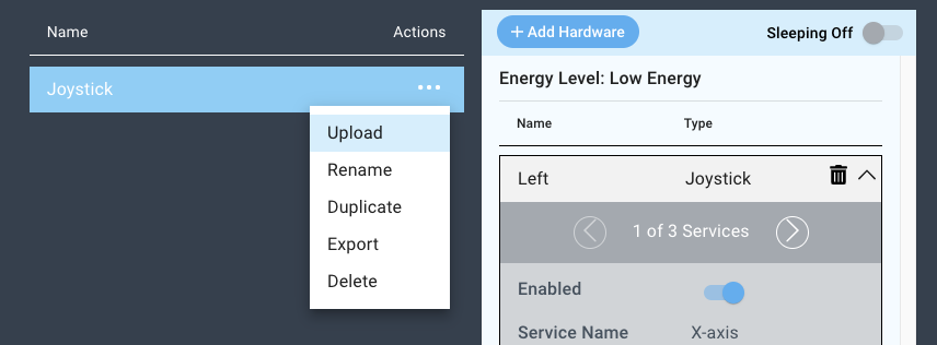
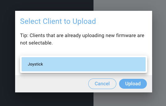
Now you can upload your firmware to the Build Base.


Build the App
| Tip |
|---|
Remember: all Apps and Firmware files are available in the resources section below! |
Navigate to the Applications page and click .

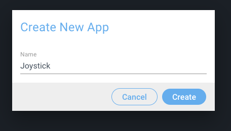
Click the “+ Create New Button”, name your application, and click create.
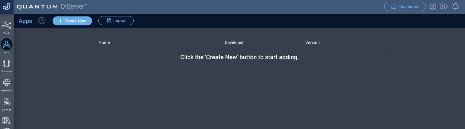

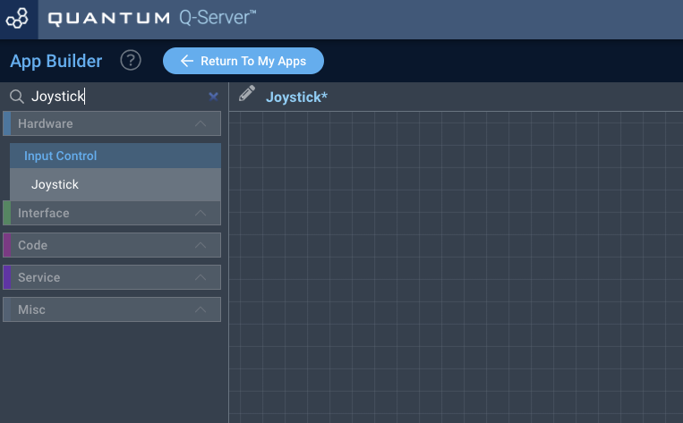
You will now be directed to the App Builder Canvas.
Using the search bar in the left hand tool-bar search for the Joystick code object and drag it .

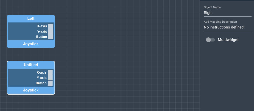
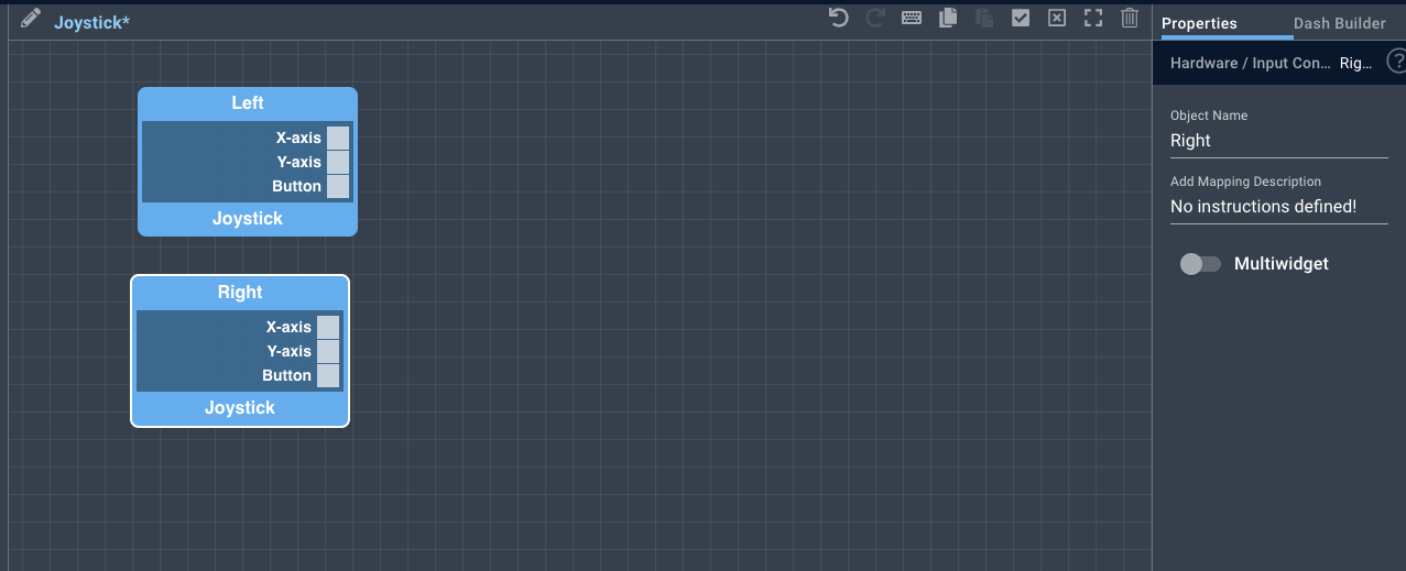
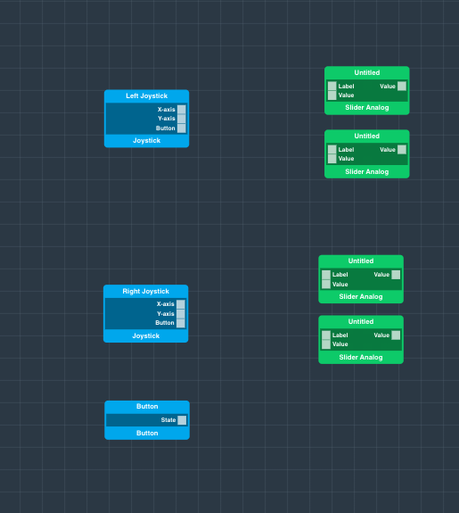
Drag and drop two Joystick hardware objects onto the canvas.
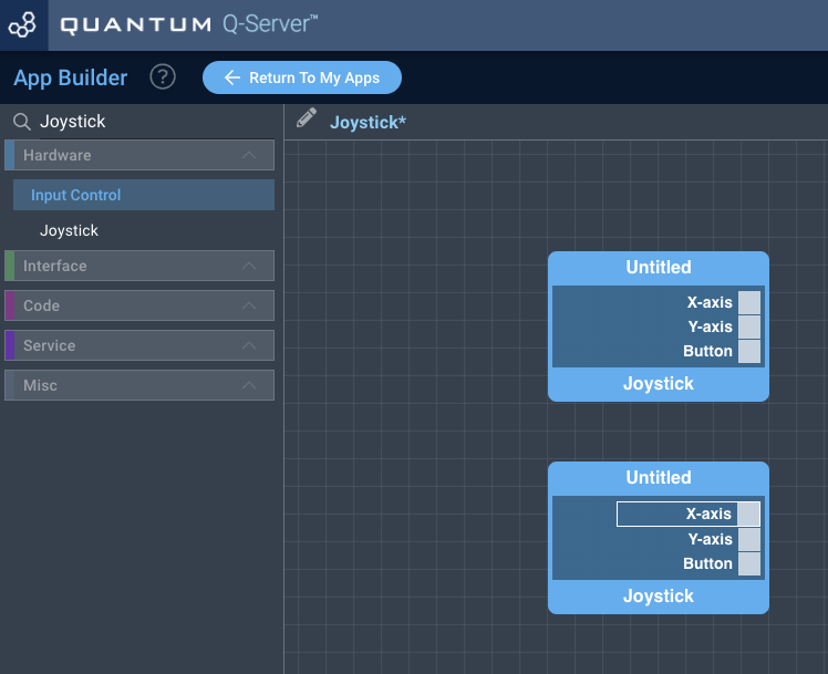

We will now name the Joystick code objects by clicking on them and editing their name in the right hand “properties” panel.

Search for a “Button” hardware object, drag it .
Drag and drop one onto the canvas, and name it accordingly.


In order to save the names you must click the “Save Properties” button at the bottom of the properties tab.


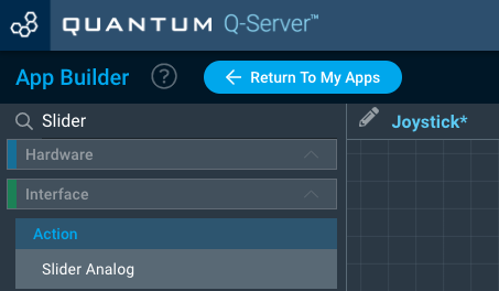
Next, search for the “Slider Analog” code object using the search bar.

Drag and drag drop four of them onto the canvas.

Search for the “Switch” object.
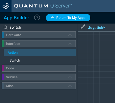
Drag and drag drop three of them onto the screencanvas.


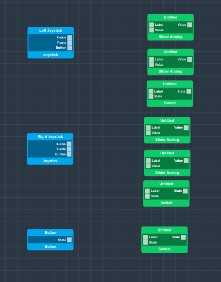
At this point you should name and label all of your interface objects (The Switches and the Analog Sliders), as this will make them easier to identify on the dashboard.
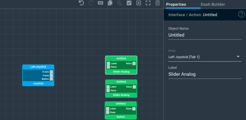
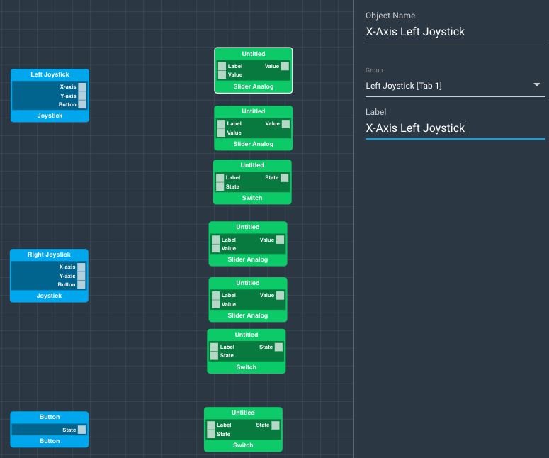
We’ll show you how to do the first one. Select the object you wish to change the name of by clicking on it. The properties panel on the right will pop open. Here you can change the “Object Name” and the “Label”.
For this first object we will change both the Label and the Object Name to “X-Axis Left Joystick”. Remember to hit the “Save Properties” tab for each object that you rename, otherwise your changes will be lost.


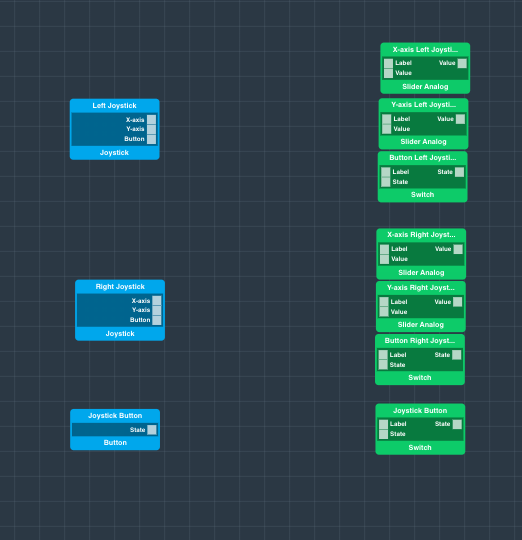
Each of your interface objects are should now be properly labeled, let’s .
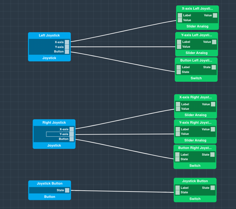
Let’s connect the Hardware hardware objects to themthe interface objects. Connect the objects as follows:


Your application is now complete! Save it and return to the Applications page.
Map the Hardware
You should now be back on the Apps page.
Find your “Joystick” app and hit the play button.
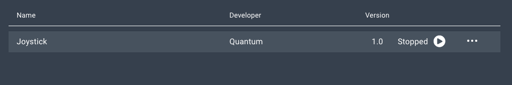

A list containing all of the devices in your application will expand.

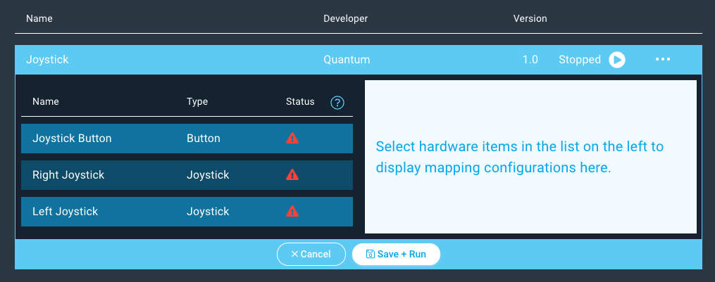
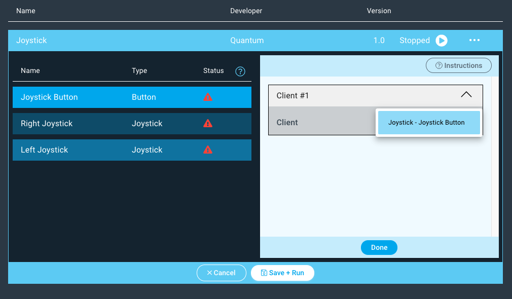
Next click on the “Button” device and the client dropdown menu will appear on the right.
Select the Button driver from the dropdown menu and hit “Done”.

Repeat the same steps for the “Right” and Joystick device.
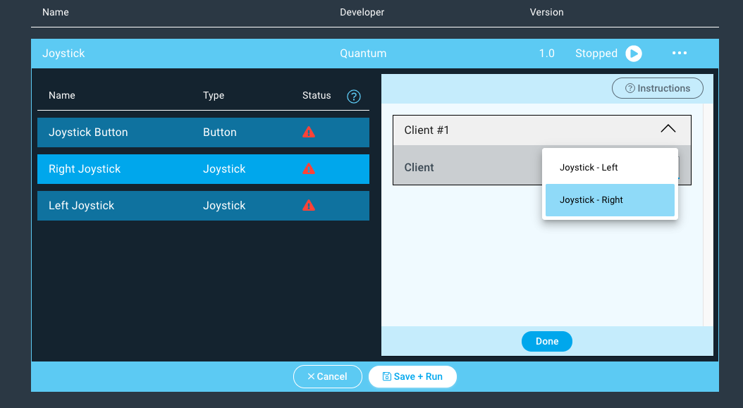
Repeat the same steps for the “Left” Joystick devicesdevice.


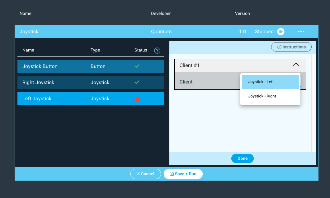
Notice how the status symbols have changed to green checkmarks.

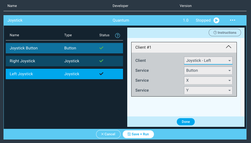
| Info |
|---|
When mapping firmware devices to objects in your Apps it is important to note that only devices and objects of the same type can be mapped together. Using this app for example, we are only given the option to map the client with the button firmware to the button object. |
Run the App!
Lastly, hit “Save + Run”

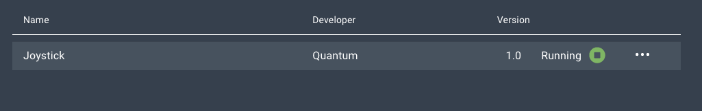
Congratulations! Your Joystick project is now complete! You can now use this as input control for RC cars and other motorized projects!


Schematics
Code
App
| View file | ||
|---|---|---|
|
Firmware
| View file | ||
|---|---|---|
|
Use the DIY Kit
You can also build this project with one of our DIY kits!
Check out the following project section of the Joystick DIY Kit page to find out how.
Gallery


Resources
App |
| ||||
|---|---|---|---|---|---|
Firmware |
| ||||
Schematic | | ||||
Fritzing |
|