Introduction
The IR Emitter GPIO driver for RGB LEDs is used in conjunction with an IR LED to emit IR signals which can control various devicesRGB LED either in common cathode or common anode layout.
Driver Parameters
The IR Emitter GPIO driver has one parameter that needs for RGB LEDs has four parameters that need to be configured:
Red Pin
This pin is connected to the red leg of the LED.
Green Pin
This pin the IR led is connected to the green leg of the LED.
Blue Pin
This pin is connected to . Amy pin is suitablethe blue leg of the LED.
Layout
This determines whether the common connection of the LED is connected to GND (common cathode) or 3.3V (common anode).
Wiring
Example
Common Cathode
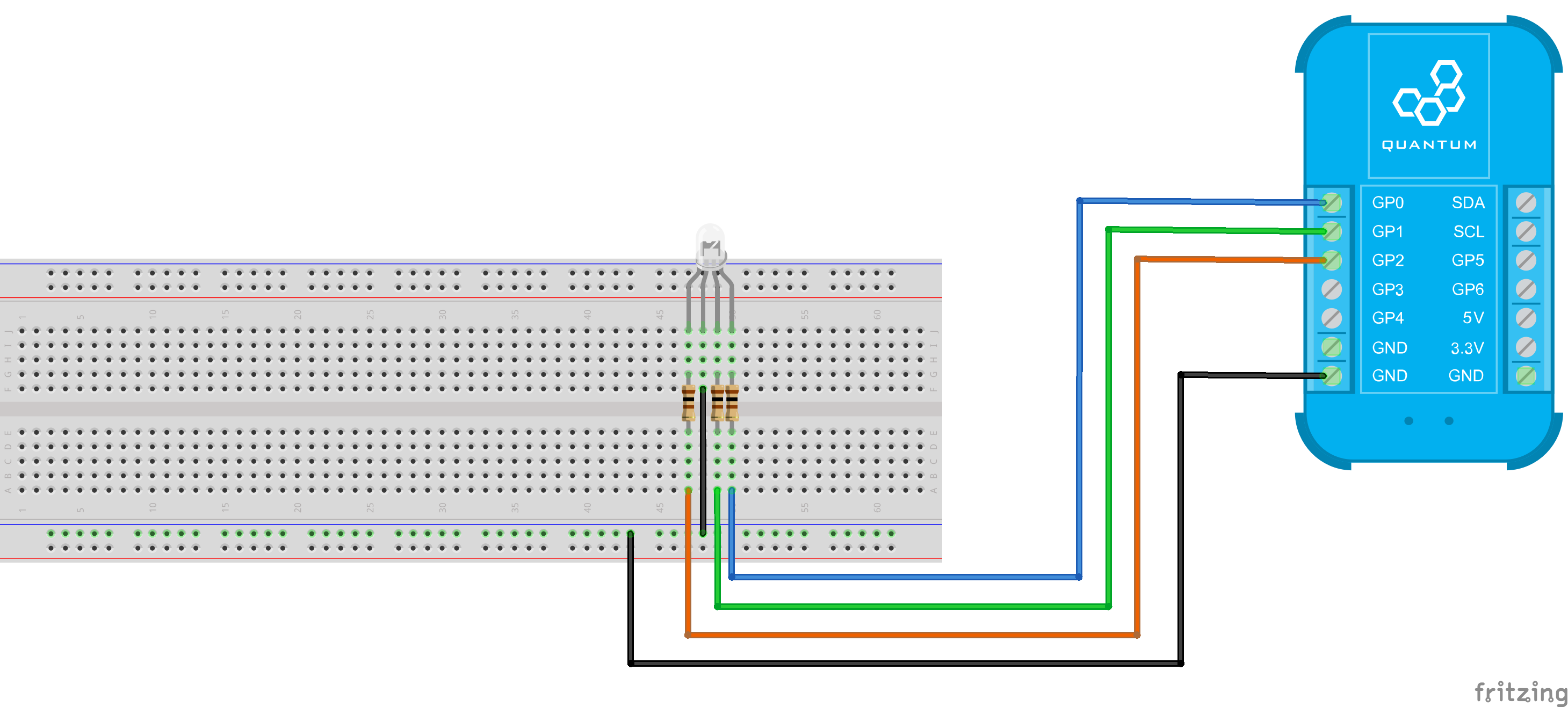
The IR led is connected to GP0 through a current limiting resistor. Special care should be given to IR LEDs since they can easily burn through. 100Ω is a good value for a driving voltage of 3.3V, which is being sourced by the GP pins.
Breadboard
GP1, GP2 and GP3 are connected to the color pins of the LED through a 100Ω current limiting resistor each. The common cathode leg is connected to GND.
Breadboard
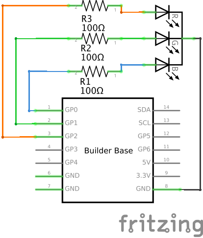
Schematic
Used Pins
Used Pins | Description |
|---|---|
GP0 (can be any GP pin) | Connected to the red leg |
GP1 (can be any GP pin) | Connected to the green leg |
GP2 (can be any GP pin) | Connected to the blue leg |
GND | Connected to the common cathode leg |
Common Anode
GP1, GP2 and GP3 are connected to the color pins of the LED through a 100Ω current limiting resistor each. The common anode leg is connected to 3.3V.
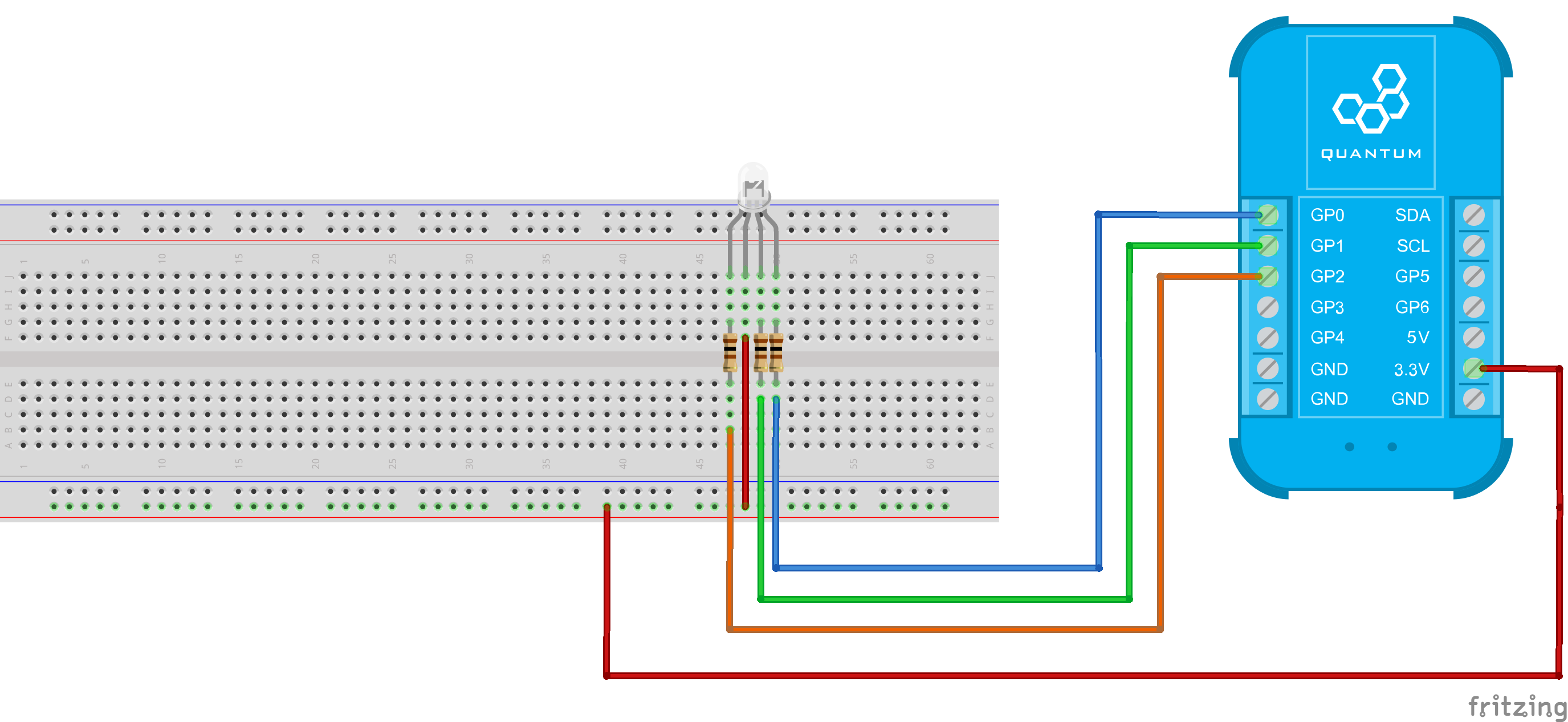
Breadboard
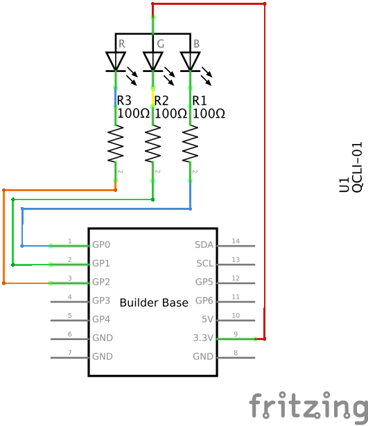
Schematic
Used Pins
Used Pins | Description | |||
|---|---|---|---|---|
GP0 (can be any GP pin) | This pin drives the IR LED | GND | This pin provides the GND | Connected to the red leg |
GP1 (can be any GP pin) | Connected to the green leg | |||
GP2 (can be any GP pin) | Connected to the blue leg | |||
3.3V | Connected to the common anode leg |
How to write an App
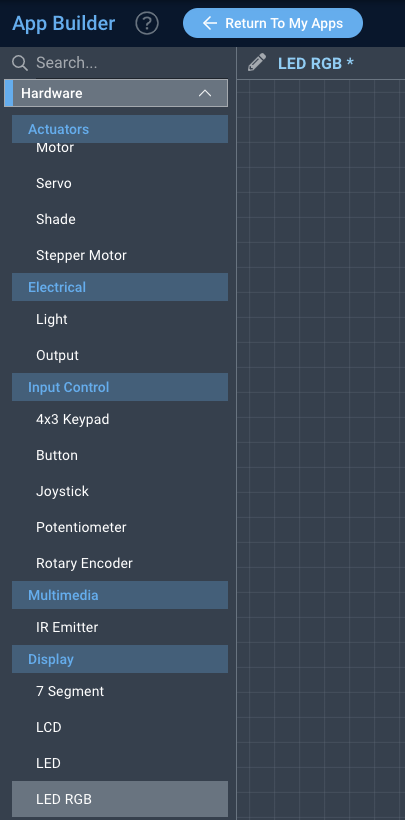
Navigate to the App Builder and create a new application. You can find the “LED RGB” code object under the “Hardware” Tab in the object drop down menu on the left, or you can also use the search bar.
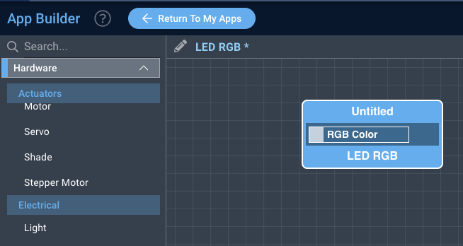
Drag the “LED RGB” object onto the canvas.
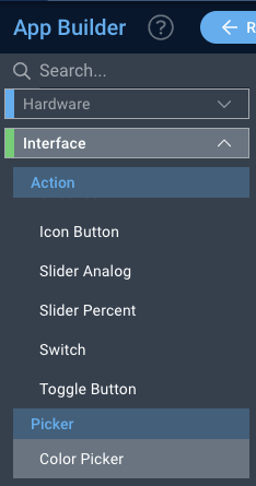
Next, located under the interface tab find the “Color Picker” object and drag it onto the canvas.
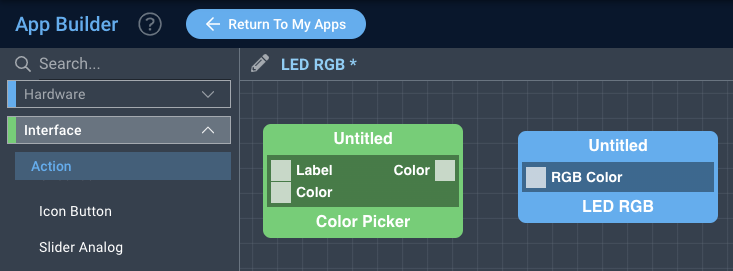
Finally, connect the Color port from the “Color Picker” object to the RGB Color port on the “LED RGB” object, label your objects, and save your application.
How to create a firmware
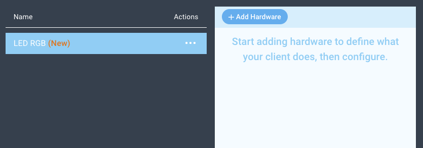
Navigate to the Firmware Builder and create a new firmware file.
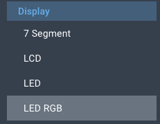
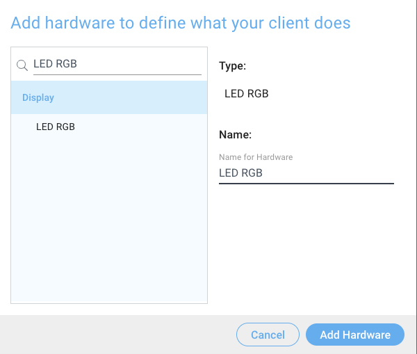
Click the “+ Add Hardware” button which will open a modal window. Scroll down in the list to find the “Display” section and select the “LED RGB” hardware option.
Give your device a name, and click “Add Hardware”
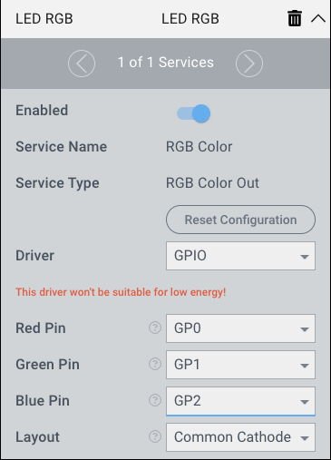
Next, select the “LED RGB” driver under the driver dropdown menu.
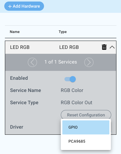
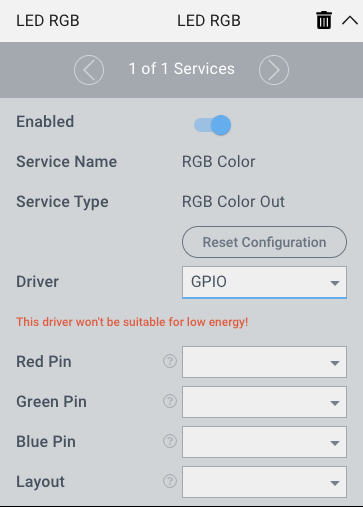
For this example we select:
Red Pin: GP0
Green Pin: GP1
Blue Pin: GP2
Layout: Common Cathode
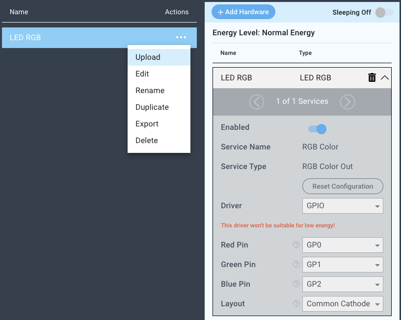
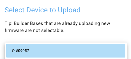
You may now save your firmware file and upload it to one of your clients.
Supported Hardware
RGB LED
Downloads
Apps
| View file | ||
|---|---|---|
|
Firmware
| View file | ||
|---|---|---|
|
Assets