| Table of Contents |
|---|
Overview
| Widget Connector | ||||||||||
|---|---|---|---|---|---|---|---|---|---|---|
|
| Info |
|---|
For Fullscreen: https://www.youtube.com/watch?v=lpROv2i29mA |
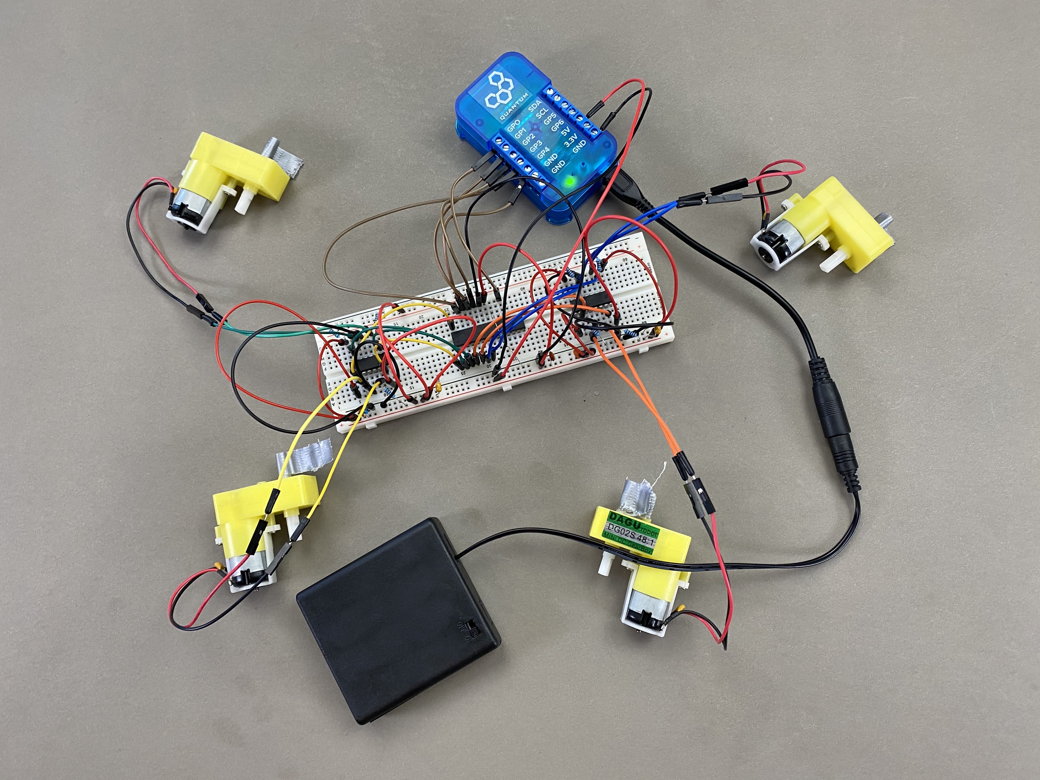
The Four Motor project is the prototype to our Four Motor Kit build. It is a fun breadboard build that will familiarize you with the use of PWM expanders and H-Bridges. You could even take this prototype and create your own chassis for it to have a quick and simple RC carThis Four Motor project serves as the basis for a simple RC car design. However, unlike our 2 Motor project this project turns by having the two sets of motors rotate in opposing directions.
You can also build this project with one of our DIY Kits!
Check out the Four Motor DIY Kit page to find out how.
|
|
|
|
|
|
|
|


 Hardware components
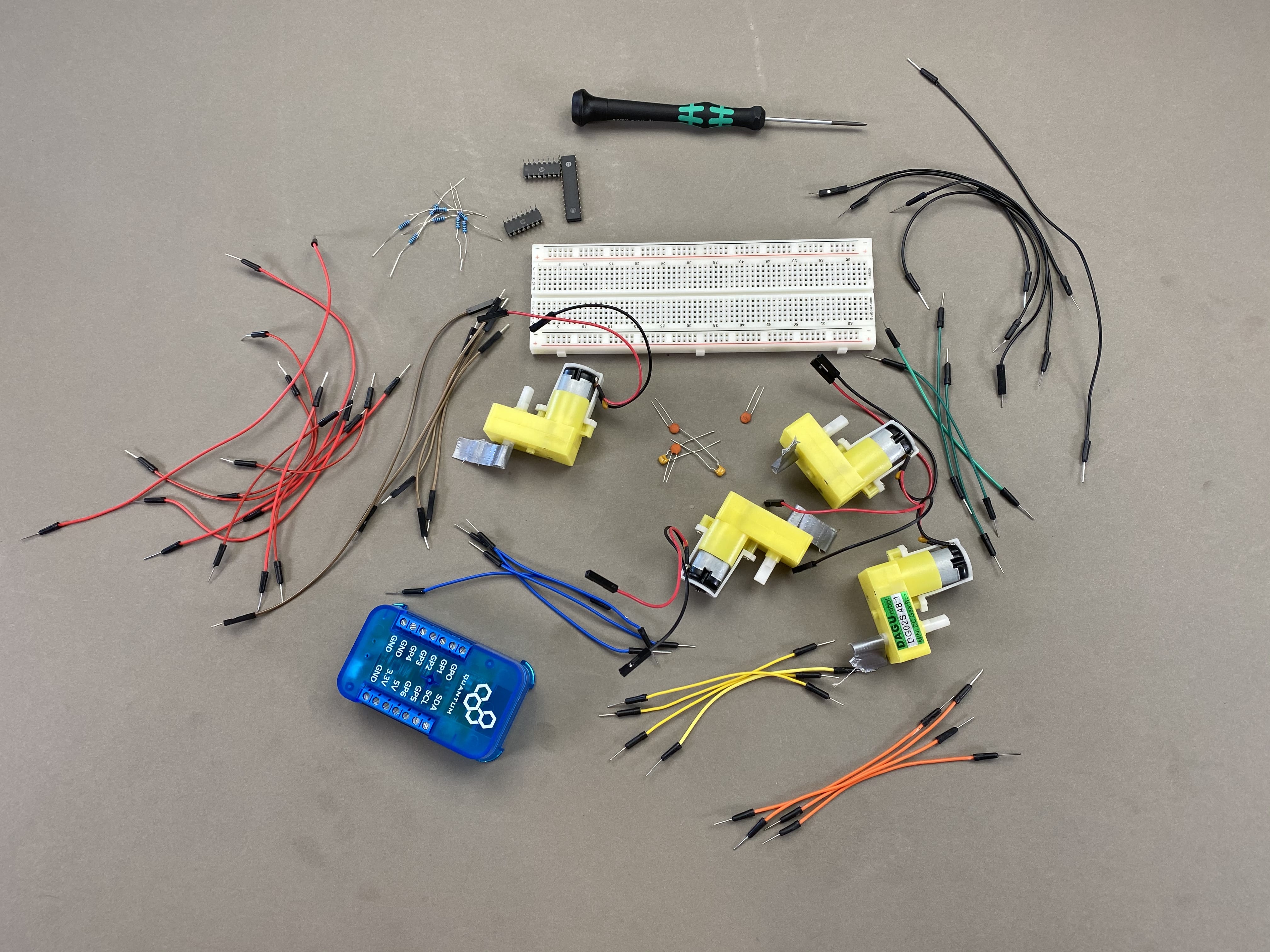
Things used in this project
Hardware Components
Picture | Name | Quantity | Link |
|---|---|---|---|
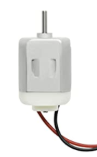 | 1 - 6V DC Motor | 4 | One is included in the Component Kit You can purchase the others here |
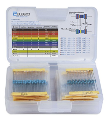 | 2kΩ Resistor | 9 | Can be purchased here |
| 220Ω Resistor | 1 | Included in Component Kit Or you can purchase it here |
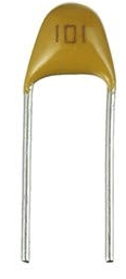 | 1uf Capacitor | 2 | Can be purchased here |
| 100nf Capacitor | 3 | Can be purchased here |
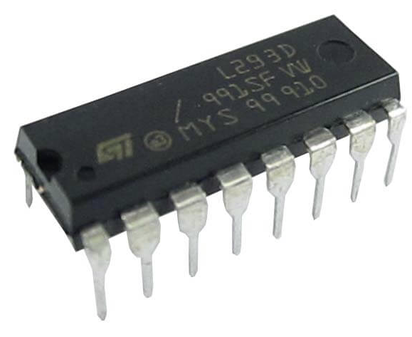 | L293D | 2 | One is included in the Component Kit, but you can purchase the second here |
 | TLC5940 | 1 | Can be purchased here |
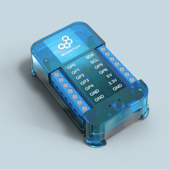 | Q-Client Builder Base | 1 |
Tools Used
Picture | Name | Quantity | Link |
|---|---|---|---|
 | Small slotted-head screwdriver | 1 | Included in the Component Kit or you can pick from one on our Recommended Tools List |
Story
The Idea
This Four Motor project serves as the basis for a simple RC car design. However, unlike our 2 Motor project this project turns by having the two sets of motors rotate in opposing directions.
Video
| Widget Connector | ||||||||||
|---|---|---|---|---|---|---|---|---|---|---|
|
Build Process
Step 1: Hardware Assembly
Assemble the Circuit
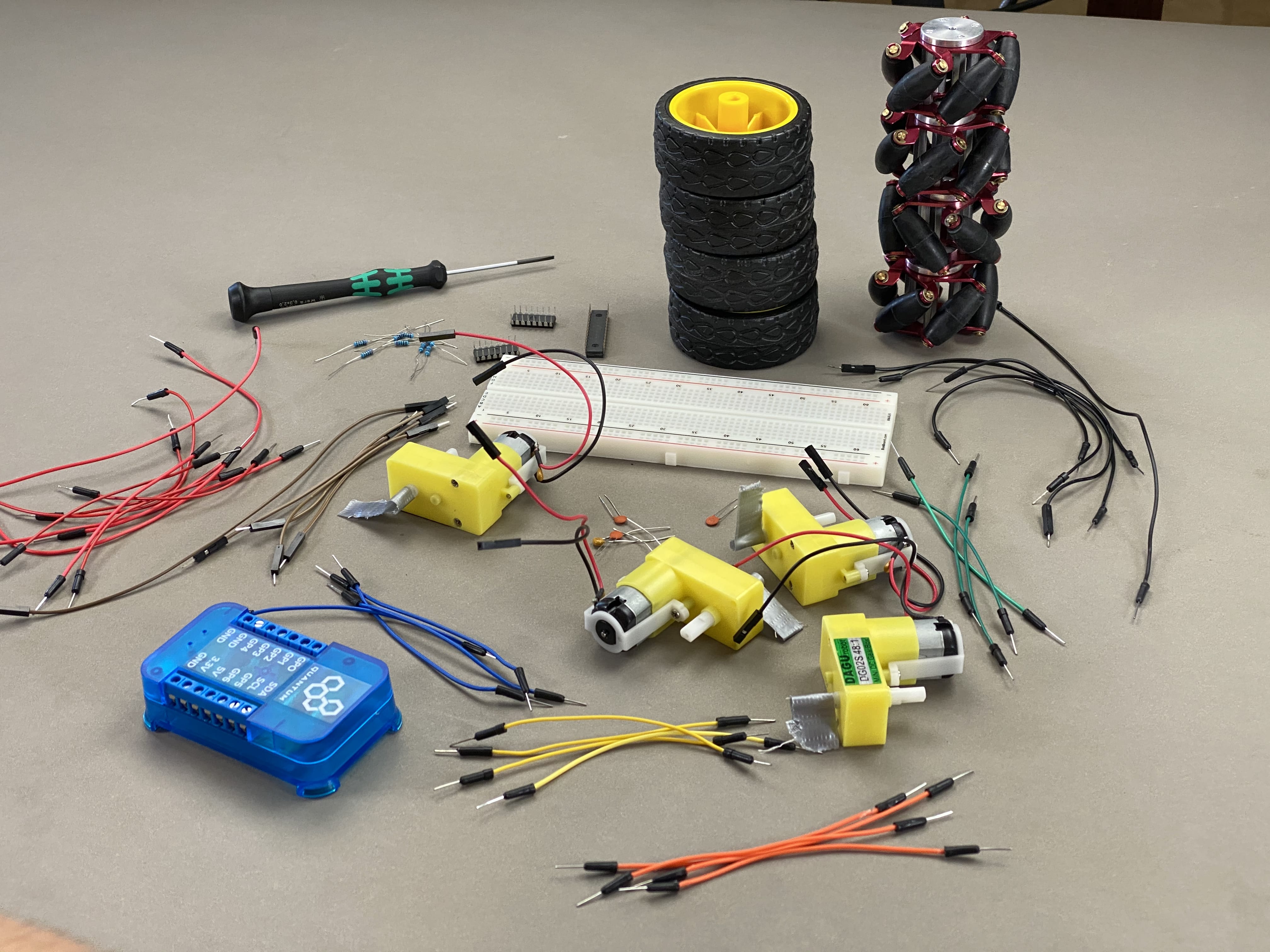
Gather all of the components in the parts list above.
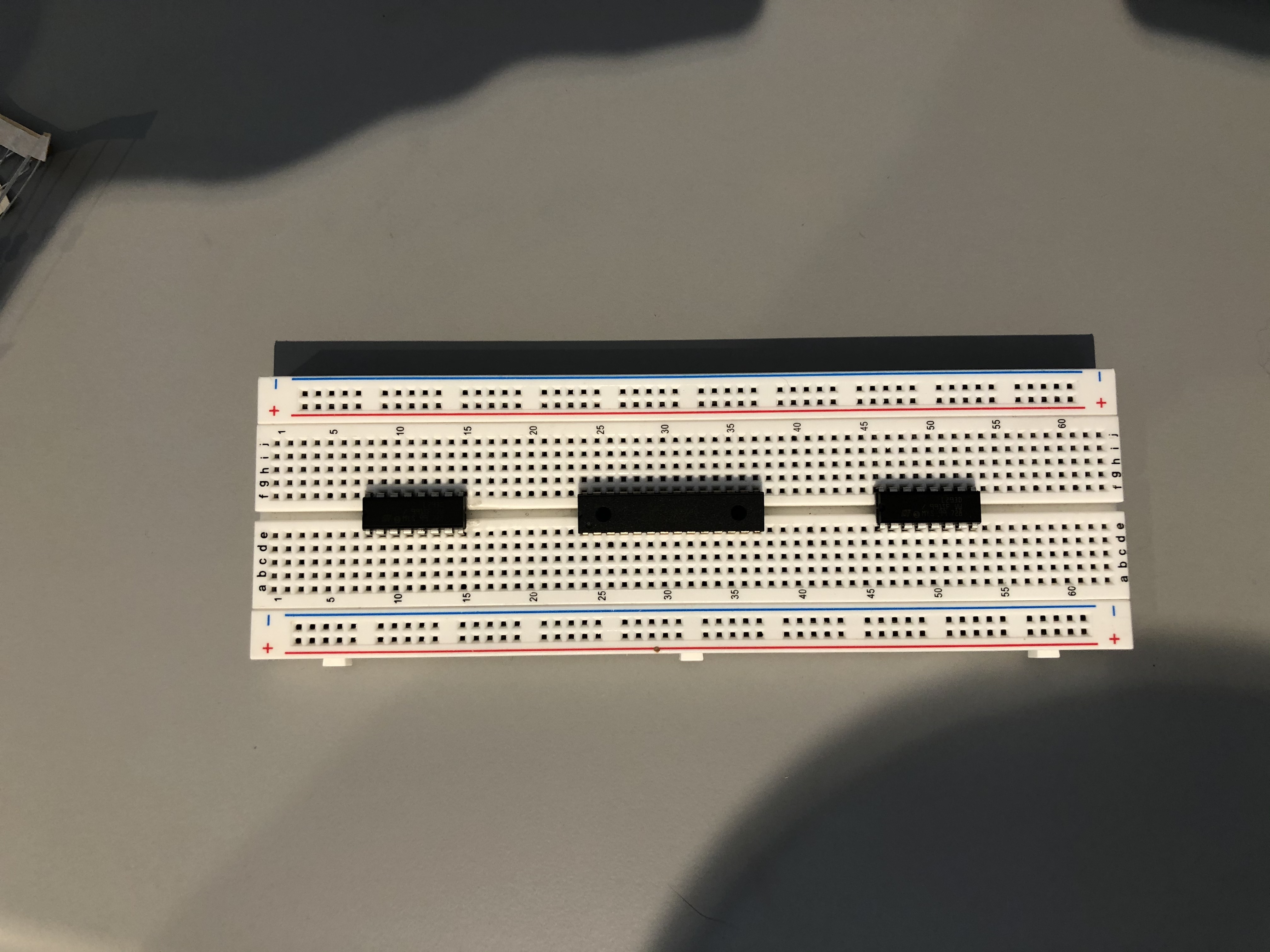
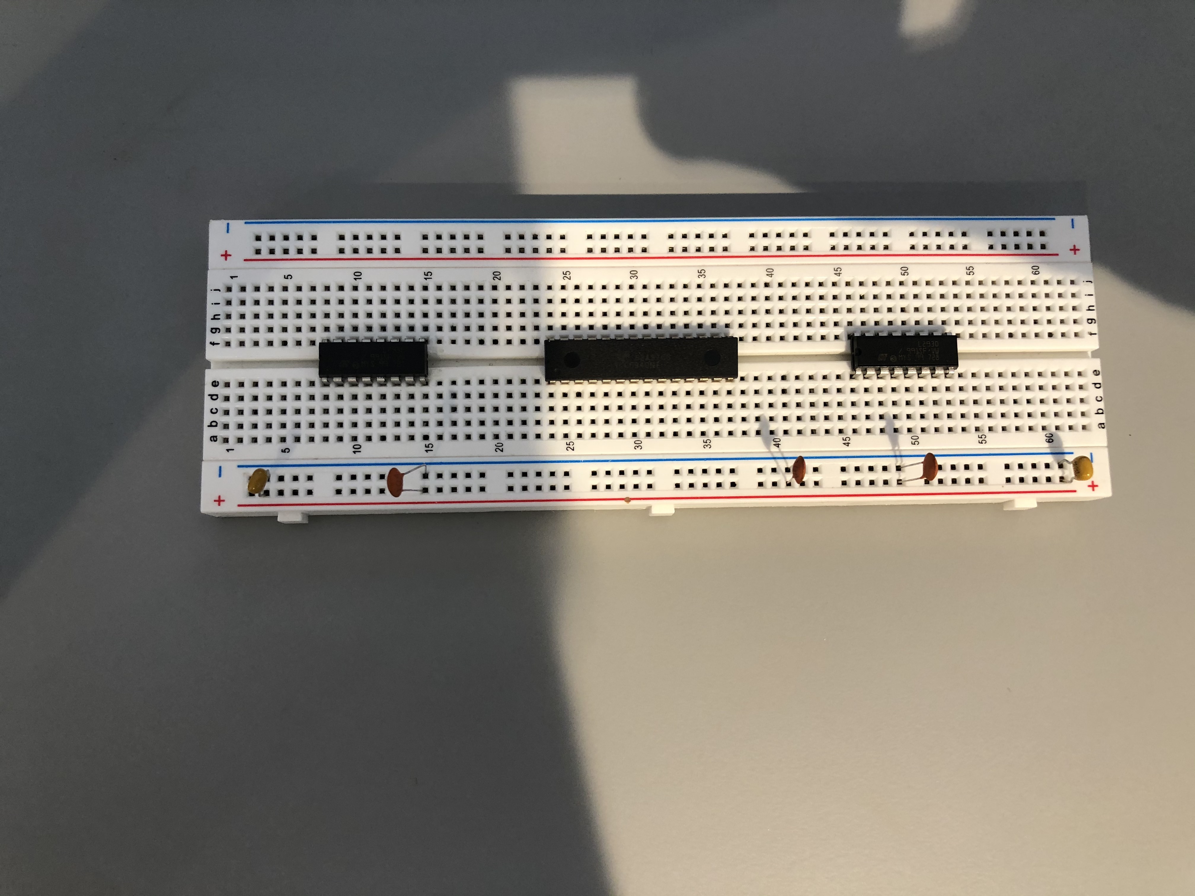
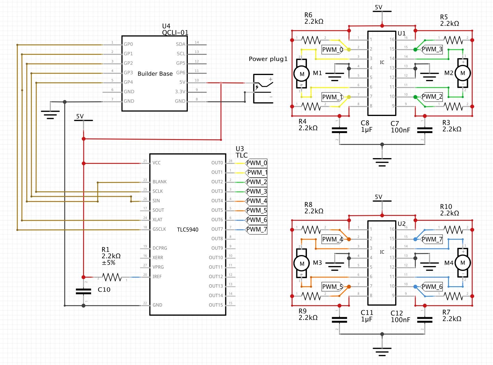
We will start by setting up our breadboard. First, put the TLC5940 chip in the middle of the breadboard and have each L293D H-Bridge on either side of the TLC5940 like so:

Now, place your three 100nf and two 1uf capacitors on the GND and VCC rails of your breadboard as follows:

Now, follow these schematics to wire each of your H-Bridges:
H1
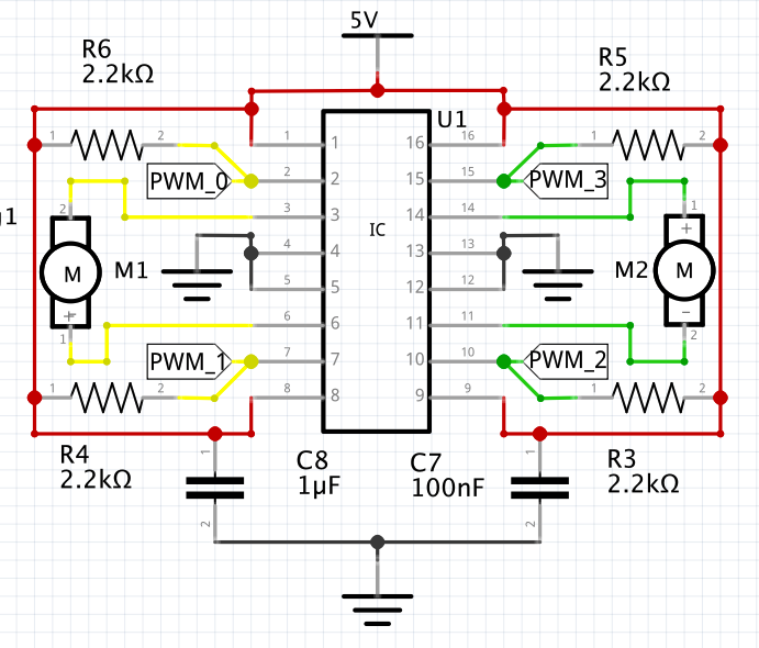

H2
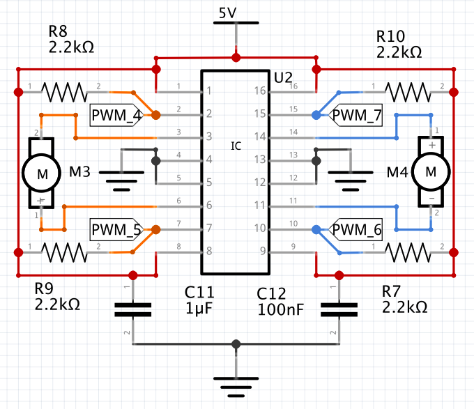

| Info |
|---|
The PWM tags on the H-Bridges will be wired to the TLC5940. The capacitors in the schematics above are the ones we already places on the Vcc and GND rails of the bread board. |
Now, follow these diagram to wire your TLC5940:
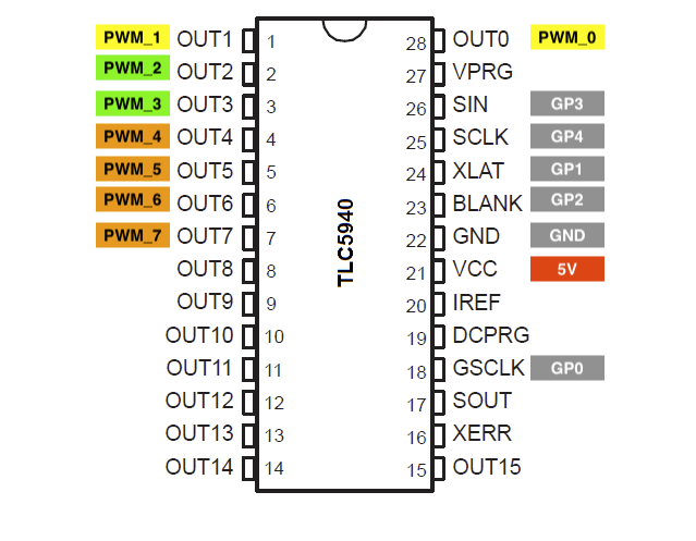


TLC5940 | Builder Base |
|---|---|
XLAT | GP1 |
GSCLK | GP0 |
BLANK | GP2 |
SIN | GP3 |
SCLK | GP4 |
GND | GND |
5V | 5V |
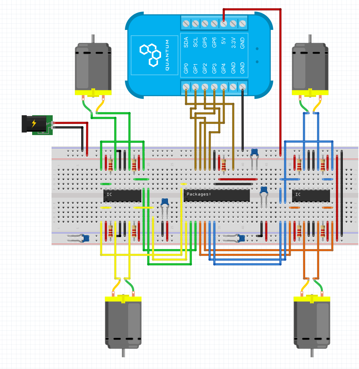
Bread Board:
Schematic:

| Note |
|---|
Be careful to make sure that you connect the Circuit to 5V and not 3.3V. If you don’t, the Mecanum car will be under powered. |
Pair the Builder Base
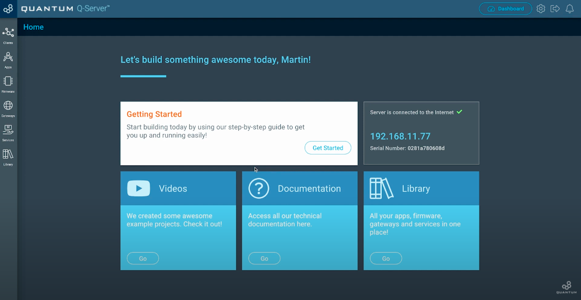
Now we want to pair the Builder Base with our Q-Server. In order to do so, go to the Homescreen of your Q-Server.
Next click on the lift side symbol labeled “Clients”. Switch to the “Unpaired” tab at the top middle of the screen.
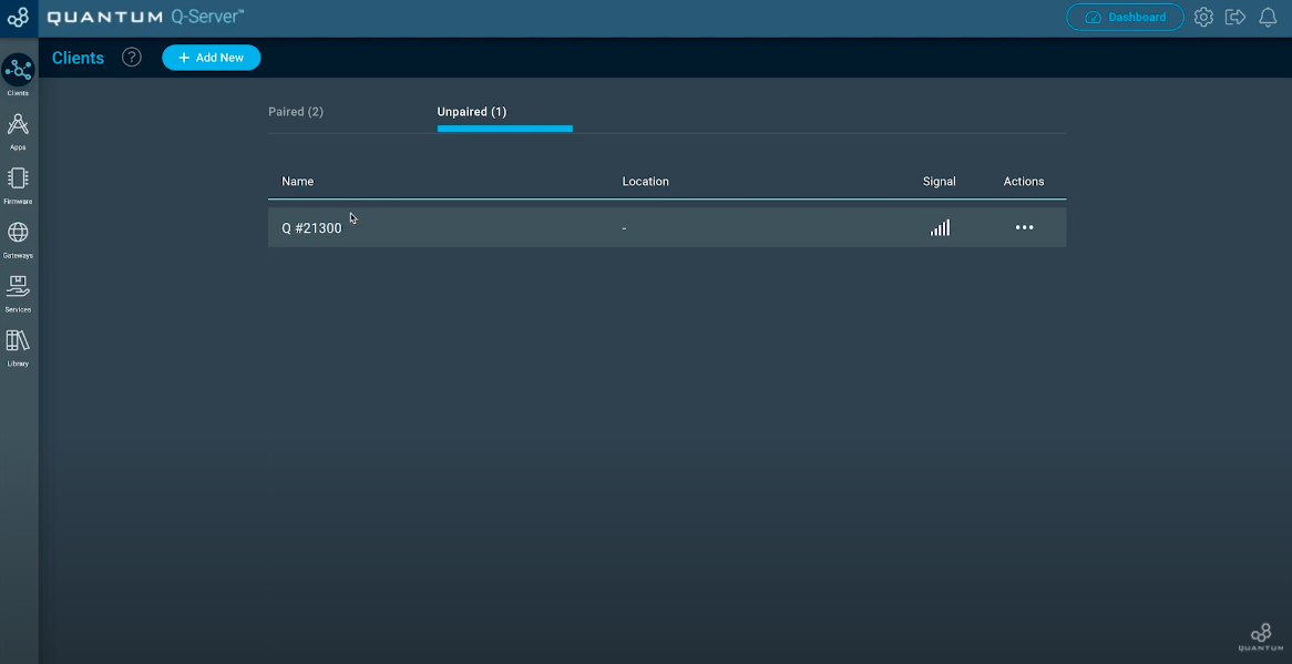
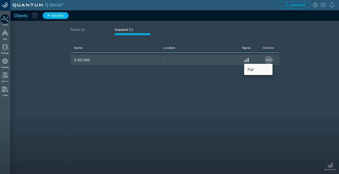
You should see your unpaired Builder Base. If not, check if you have plugged in the power supply for the Builder Base. Now move to the three dots below “Actions” and click “Pair”.
Once your Client is paired, click the “Setup” button.
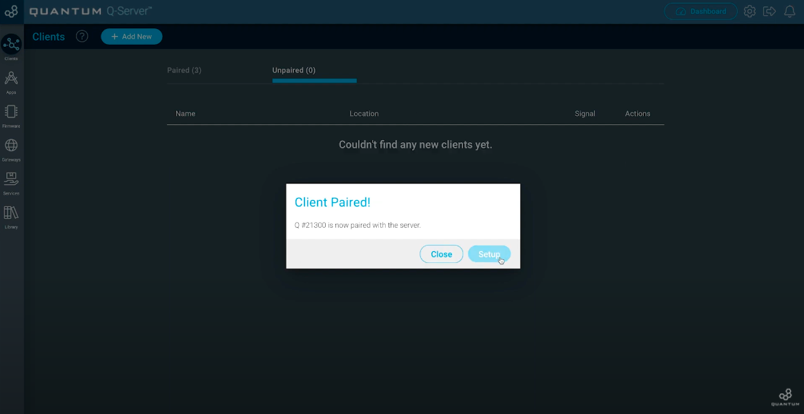
Now you can edit your Client. Give him a Name you want and also a location where you are going to use it.
Step 2:Hit “Save” when you finished.
Build the Firmware
| Tip |
|---|
Remember: All Apps and Firmware Files are available in the resources section at the bottom of the page! |
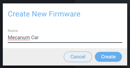
Navigate to the Firmware Builder and create a new Firmware file. We named ours “Mecanum Firmware”.

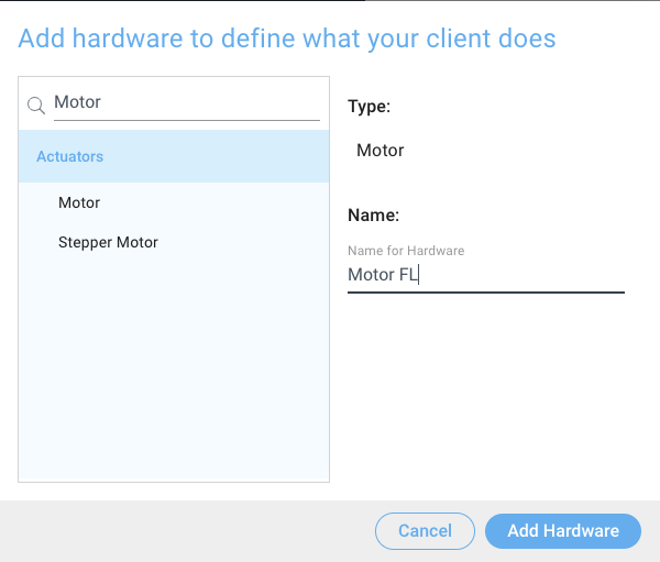
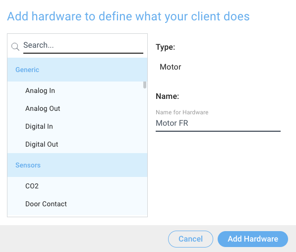
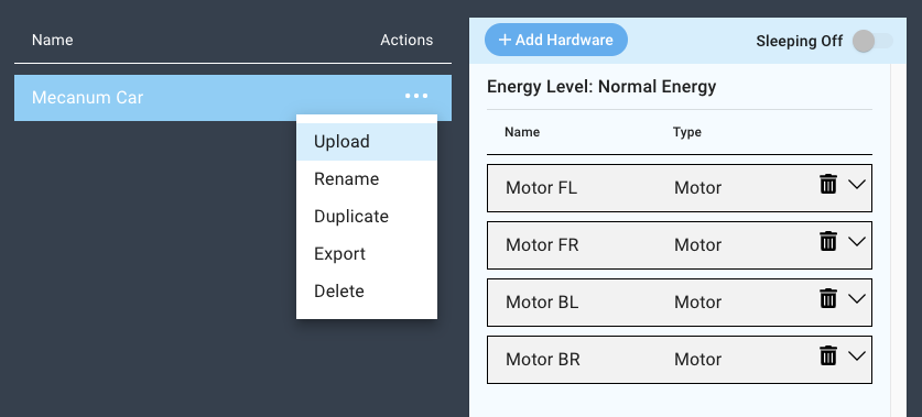
Next, click the “+ Add Hardware” button and find the Motor device via the search bar, select it, name it, and then click “Add Hardware”. We named ours “Motor FL” (Front Left).

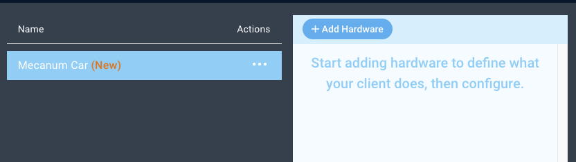

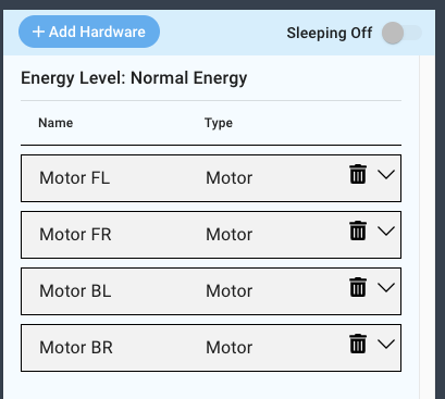
Now, repeat these steps three more times, naming the Motors “Motor FR”, “Motor BR”, and “Motor BL”.
You should now have four motor devices in your firmware file.

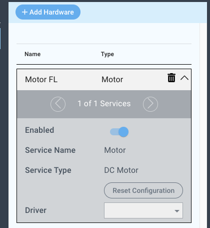
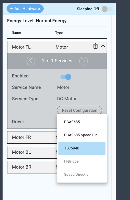
To configure the drivers for the Motor FL device, select the TLC5940 Driver from the driver dropdown menu.
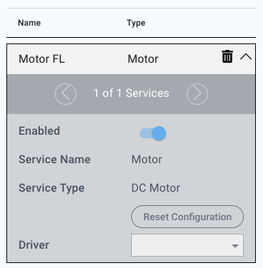

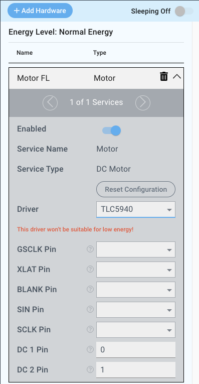
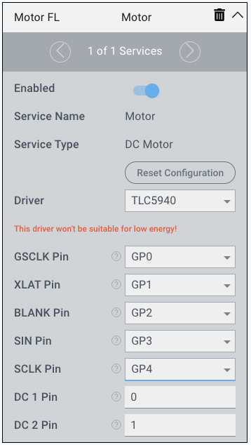
Now, set the pins accordingly:
GSCLK | XLAT | BLANK | SIN | SCLK | DC 1 | DC 2 | |
|---|---|---|---|---|---|---|---|
MFL | GP0 | GP1 | GP2 | GP3 | GP4 | 0 | 1 |

Repeat these steps for the three remaining motors. You can find the proper pin configurations in the table below.
GSCLK | XLAT | BLANK | SIN | SCLK | DC 1 | DC 2 | |
|---|---|---|---|---|---|---|---|
MFR | GP0 | GP1 | GP2 | GP3 | GP4 | 2 | 3 |
MBL | GP0 | GP1 | GP2 | GP3 | GP4 | 4 | 5 |
MBR | GP0 | GP1 | GP2 | GP3 | GP4 | 6 | 7 |
You have now finished configuring your firmware, so save your firmware by clicking the “Save button” at the bottom of the screen.


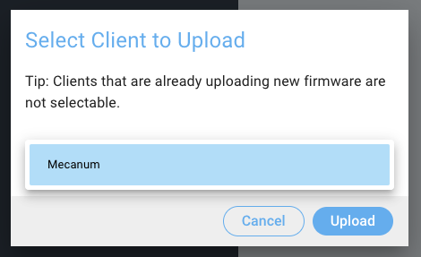
Now you can upload your firmware to the client you have attached to the 4-motor circuit.


Build the
ApplicationApp
| Tip |
|---|
Remember: All Apps and Firmware Files are available in the resources section at the bottom of the page! |
Navigate to the Applications page and click the “+ Create New Button”, name your application, and click create.
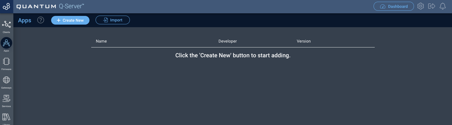


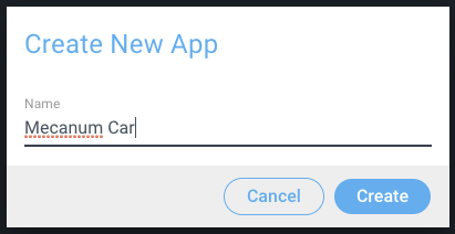
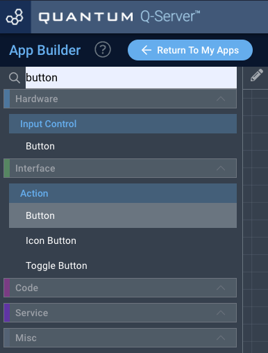
You will now be directed to the App Builder Canvas.
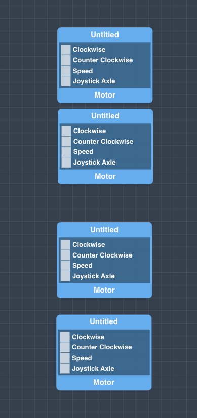
Using the search bar in the left hand tool-bar search for the Motor code object and drag four of them onto the canvas.
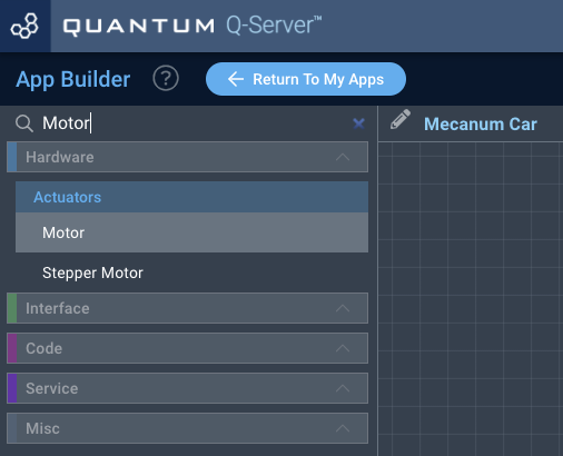


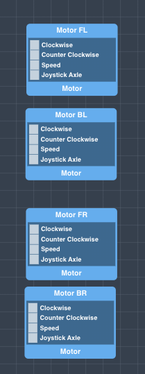
Name the Motor objects as we do, this will help you to identify the motors during the application mapping. To rename them, click on the motor object and change the name in the properties panel on the right.
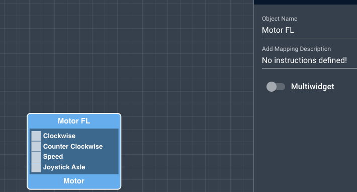


In order to save the names you must click the “save properties” button at the bottom of the properties tab.


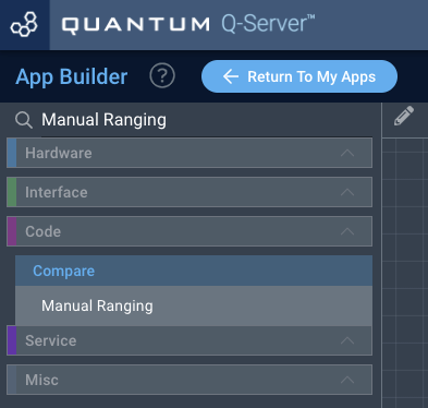
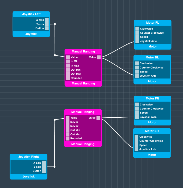
Next, search for the “Manual Ranging” code object using the search bar and drag two of them onto the canvas.

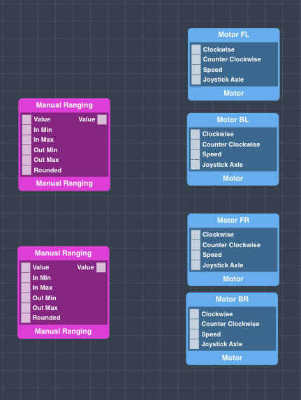

Configure each manual Ranging object as follows:
Value | In Min | In Max | Out Min | Out Max | Rounded |
|---|---|---|---|---|---|
Trigger: on | 0 | 4095 | 4095 | 0 | true |
| Info |
|---|
To configure each port on the object click on the port and change the properties in the properties panel on the right side of the screen, and hit save properties at the bottom of the screen. If you don’t your changes will not be saved! |
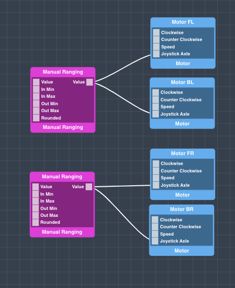
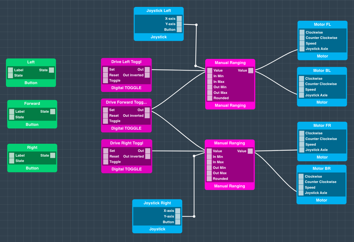
Next, connect each of the Value Out ports from the Manual ranging objects to the Motor objects as follows:

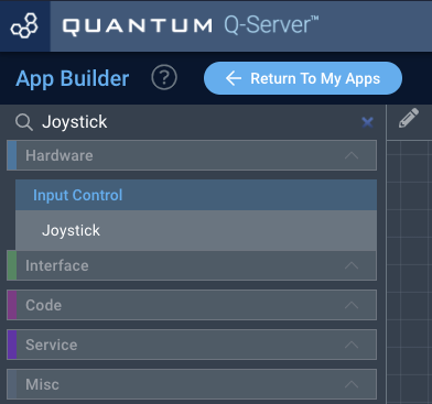
Now search for the “Joystick” object and drag two of them onto the canvas. Name one Joystick Left, and the other Joystick Right.

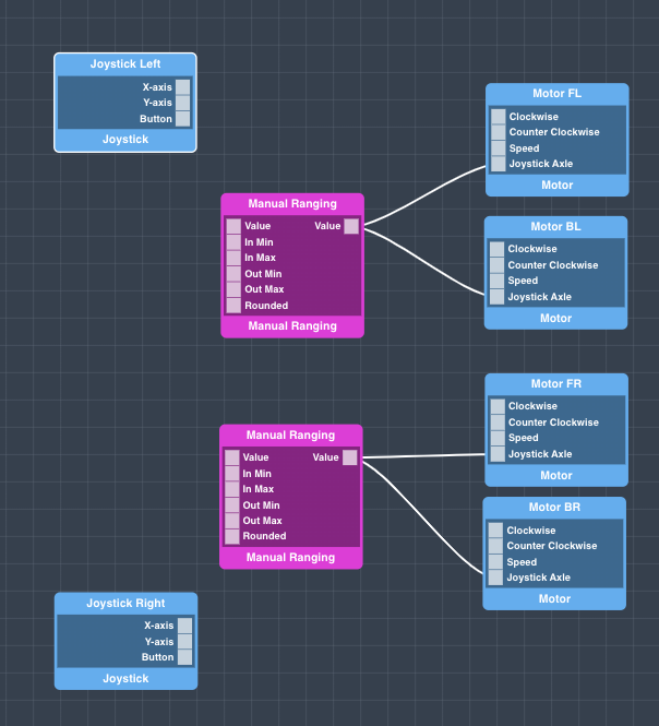

Now connect the Y-Axis ports from the Joystick objects to the Manual Ranging objects as follows:

Now, in this state your App will work with a joystick, but we are going to finish the App by also making it steerable using the dashboard interface.
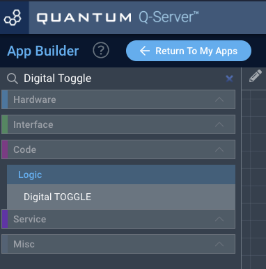
Find the Digital Toggle Code object, drag three of them onto the screen, and name them.


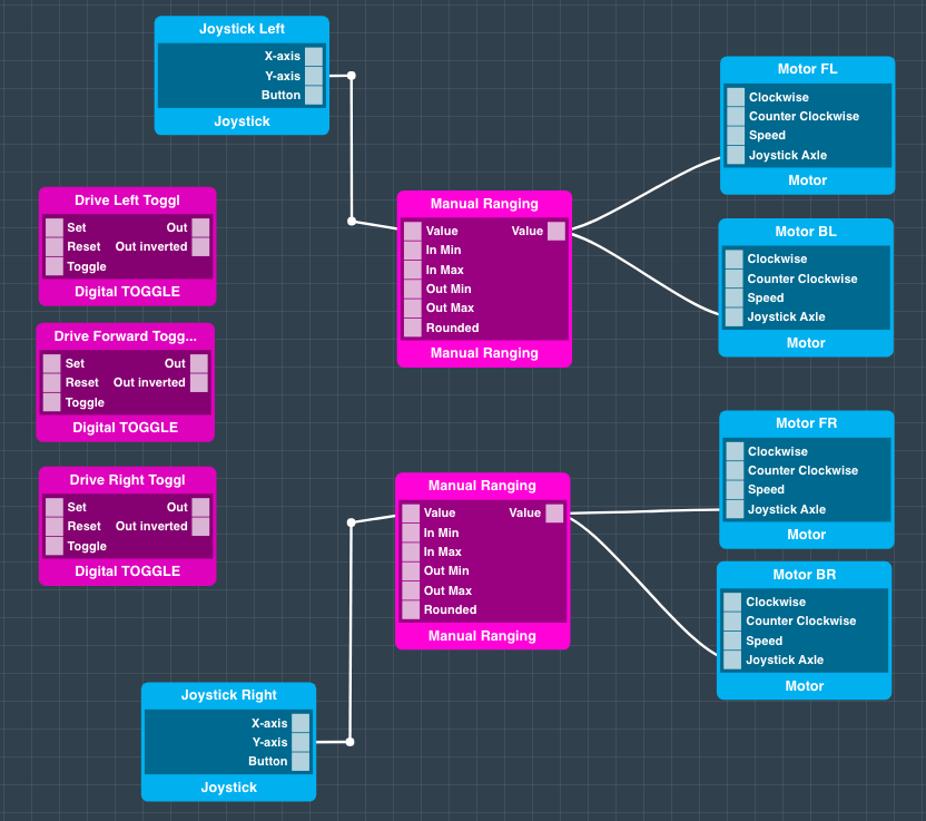
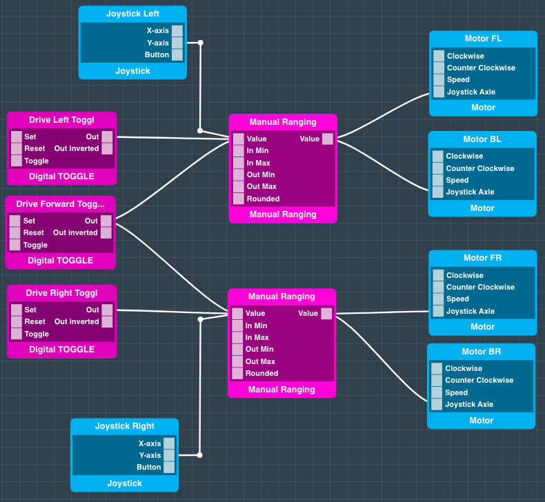
Connect the Digital Toggle objects to the manual ranging objects as follows:

Now, we just need to add buttons, so search for them and add three of them to your application.
| Info |
|---|
Be sure to add the green “interface” button objects and not the “hardware” version of the button object. |


| Info |
|---|
Name and label them, Left, Forward, and Right by use of the properties panel. If you don’t name/label them it will be confusing to determine which button does what when controlling the car via the dashboard. |
Connect the Button objects to the Digital Toggle objects as follows:

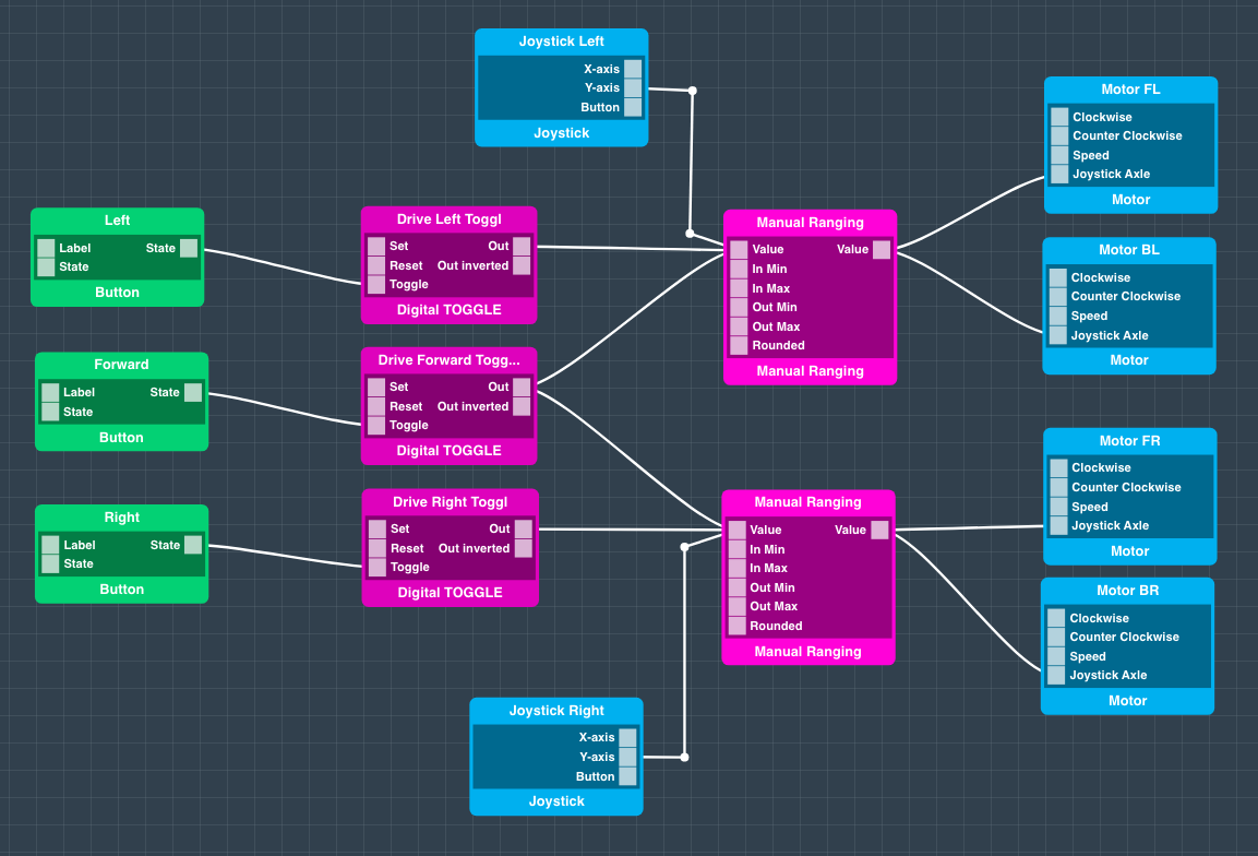
Congrats! Your app is now complete.
Hit “Save App” and go back to your applications page.
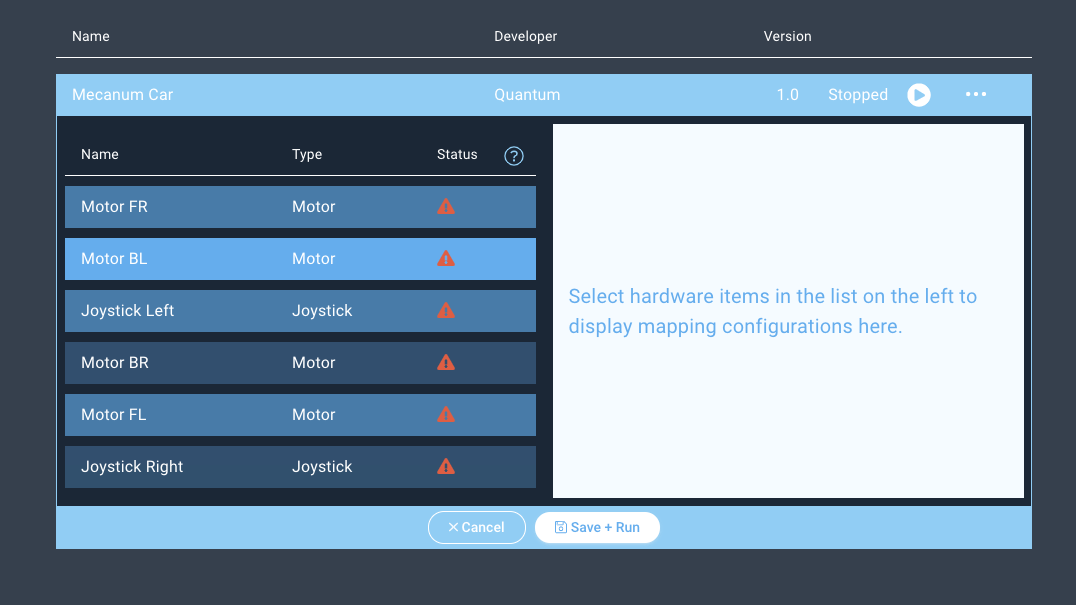
Step 4: Map Your ApplicationMap the Hardware
You should now be back on the Apps page.
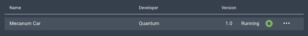
Find your “Mecanum Car” app and hit the play button.

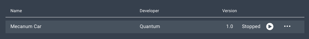
A list containing all of the devices in your application will expand.
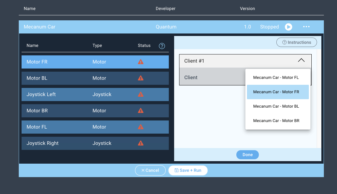
Next click on the “Motor FR” device and the client dropdown menu will appear on the right.

Select the Motor FR driver from the dropdown menu and hit “Done”.

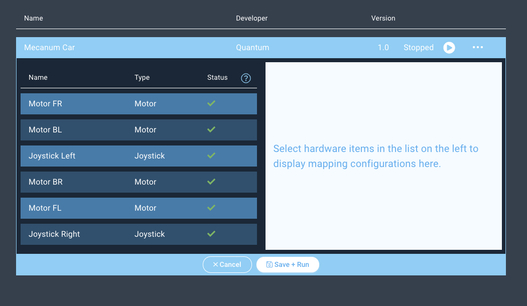
Repeat the same steps for the Motor FL, BR, and BL devices, ensuring that you match the device name to the object name.
Now you can map the Joystick Devices in the same way, but make sure that you match the Left and Right Joystick drivers with the Left and Right Joystick devices.
If you have yet to build a Joystick project you can find out how to build one here:
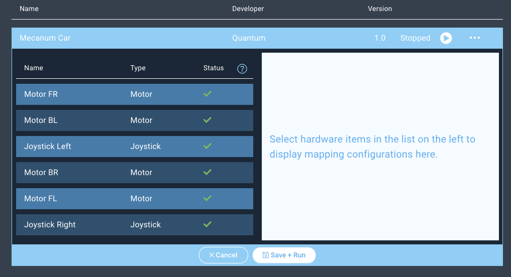
Notice how the status symbols have changed to green checkmarks.

| Info |
|---|
When mapping firmware devices to objects in your Apps it is important to note that only devices and objects of the same type can be mapped together. Using this app for example, we are only given the option to map the client with the button firmware to the button object. |
Run the
ApplicationApp!
Next, hit “Save + Run”.

Congratulations! Your project is now complete. Have fun!


Resources
CodeApplication |
|---|
App

Resources
App
| View file | ||
|---|---|---|
|
| ||||
Firmware |
|
|---|
Use the DIY Kit
You can also build this project with one of our DIY kits!
Check out the following project section of the Four Motor DIY Kit page to find out how.
Gallery
|
Schematic |
|---|
|
Diagram | |
|---|