Introduction
The 4-Phase stepper motor driver is used to control unipolar stepper motors in conjunction with a darlington transistor driver or any circuitry that amplifies the current of the output pins. The signals from the Builder Base are what the motor requires but transistor driver is needed to provide enough current to the coils in the stepper motor. We need four channels of the driver, a typical one would be the ULN2003.
Driver Parameters
The 4-Phase Stepper Motor driver has six parameters that need to be configured:
Pin 1
This pin is connected to the first coil
Pin 2
This pin is connected to the second coil
Pin 3
This pin is connected to the third coil
Pin 4
This pin is connected to the fourth coil
RPM
This is the revolutions the motor performs per minute. We can handle revolutions per minute between 5 and 60 with the default being 10.
Steps/Rev
The steps per revolutions tells the driver how often the coils have to be energized to determine a full rotation. This value can be found very prominently in the datasheet of the motor.
Wiring
A widely used driver is the ULN2003. The pinout can be found below:
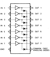
We connect the common of the free wheeling diodes to the same signal as our common wire from the motor coils. In our case to the input voltage for the motor we use.
Example
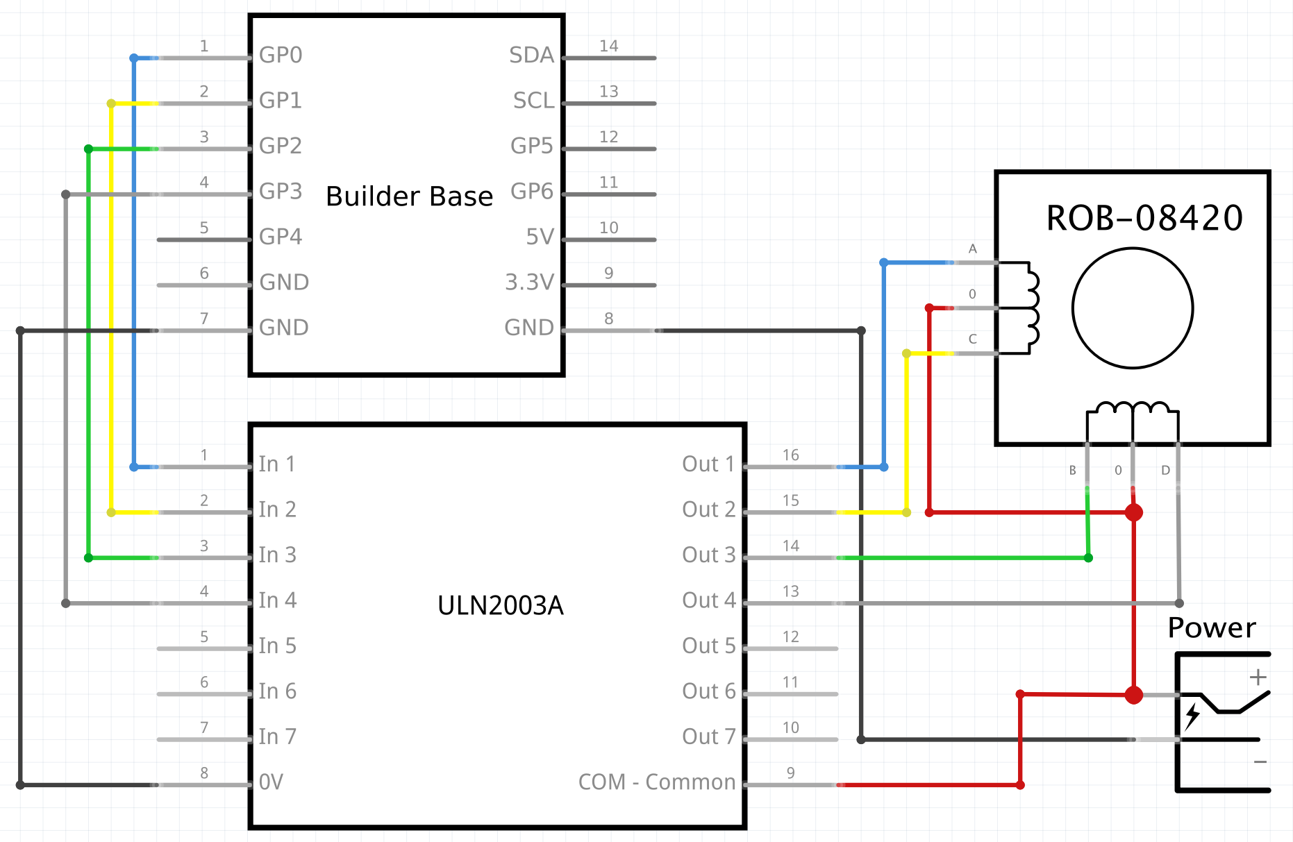
In this example, the 4-Phase Stepper motor is connected to an ULN2003 driver IC. From the Builder Base, the GND pins are connected to the GND pin on the power supply and the GND pin on the ULN2003. GPO is connected to Input 1, GP1 to input 2, GP2 to Input 3, and GP3 to Input 4. From the chip, output one is connected to A, output 2 is connected to C, output 3 is connected to B, and output 4 is connected to D. Lastly, the positive voltage from our power supply is connected to the COM (common) pin on the chip, and the 0 pins on each of the coils. We use an external power supply for the motor voltage here because most stepper motors run on 12V.
**Note: Depending on the manufacturer of the stepper motor used, the pins on each of the coils may be labeled differently. In the case of our schematic it is A, B, C and D. It might be 1, 2, 3 and 4 as well in other cases. However, as long as you are using a 4-Phase stepper motor the functionality and pin layout will remain the same. All that matters is that the pins are connected in order.
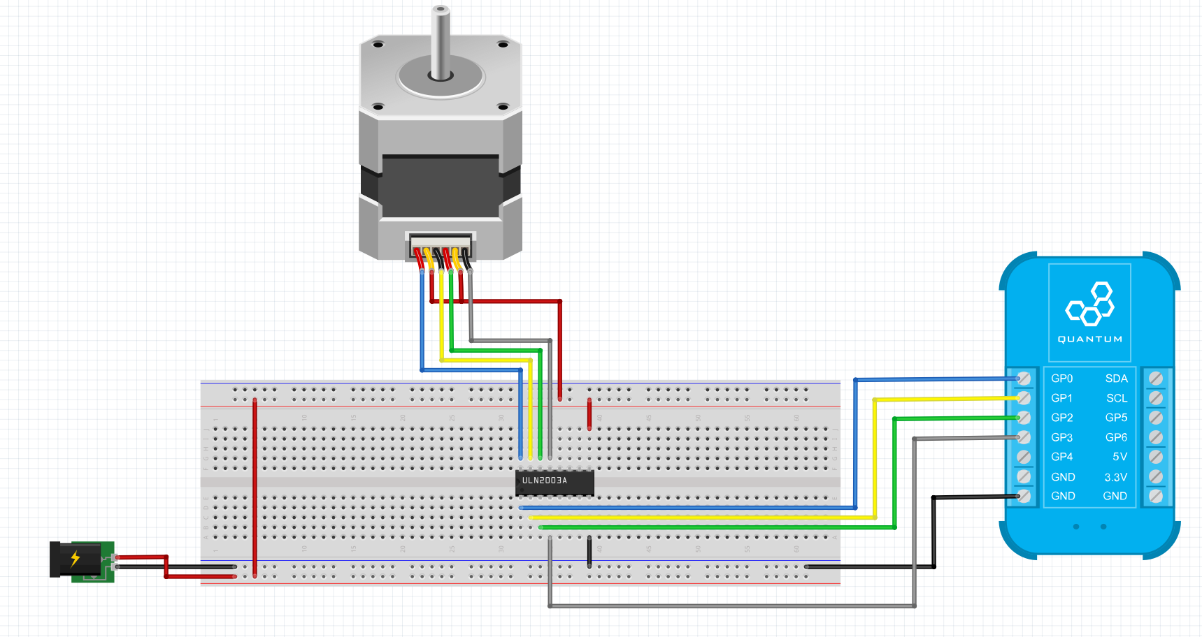
Breadboard
Schematic
Used Pins
Used Pins | Description |
|---|---|
GP0: (Can be any GP pin) | Used to control pole A; Connected to Input 1 |
GP1: (Can be any GP pin) | Used to control pole C; Connected to Input 2 |
GP2: (Can be any GP pin) | Used to control pole B; Connected to Input 3 |
GP3: (Can be any GP pin) | Used to control pole D; Connected to Input 4 |
+ voltage (from power supply) | Provides power to COM pin on the IC to the free wheeling diodes and the common coil taps on the stepper |
GND: | Provides grounding for the circuit: Connected to GND on IC, and the power supply. |
How to write an App
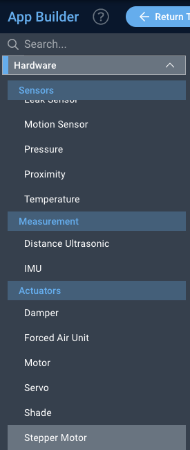
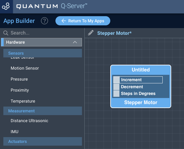
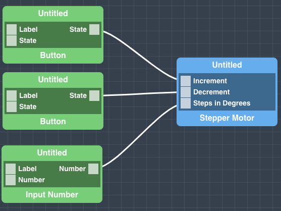
Navigate to the App Builder and create a new application. You can find the “Stepper Motor” code object under the “Hardware” Tab in the object drop down menu on the left, or you can also use the search bar.
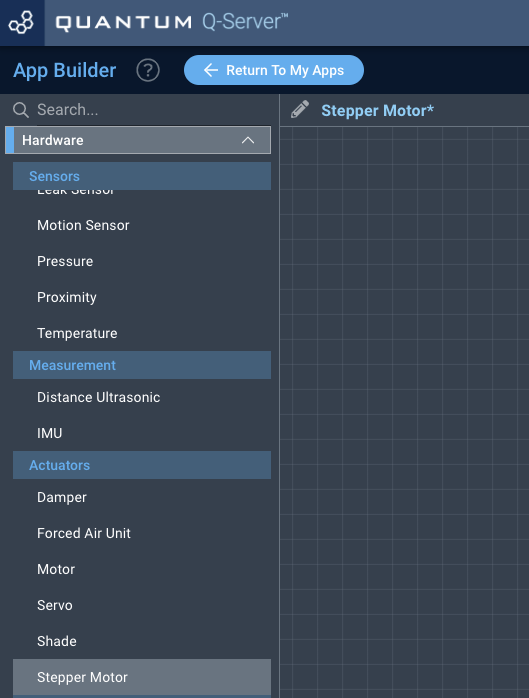
Drag the “Stepper Motor” Object onto the canvas.
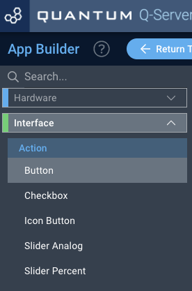
Next, locate the “Button” and “Input Number” Objects under the interface tab and drag two instances of the “Button” Object and one instance of the “Input Number” Object onto the canvas.
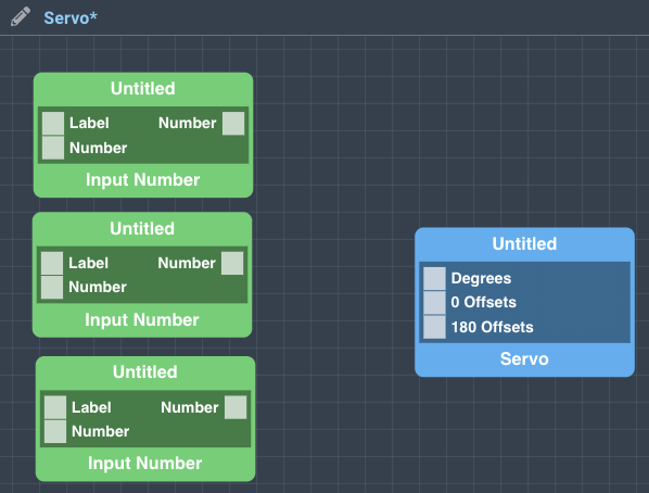
Finally, from the “Button” Objects connect one state port to the Increment port and one state port to the Decrement port on the “Stepper Motor” Object. From the “Input Number” Object connect the Number port to the Steps in Degrees port. If you wish, label your code objects for easier identification on the dashboard, and save your application.
How to create a firmware
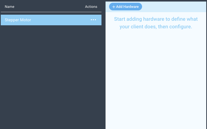
Navigate to the Firmware Builder and create a new firmware file.
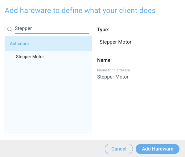
Click the “+ Add Hardware” button which will open a modal window. Scroll down in the list to find the “Generic” section and select the “Stepper Motor” hardware option.
Give your device a name, and click “Add Device”
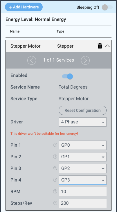
Next, select the “4-Phase ” driver under the driver dropdown menu.
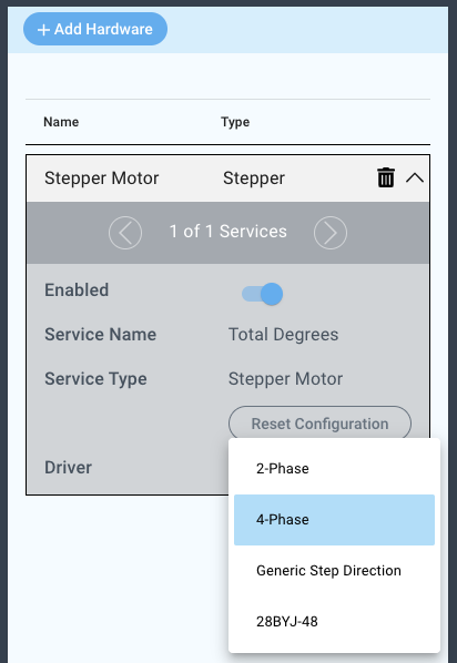
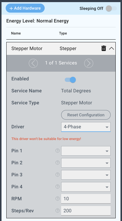
For this example we select:
Pin 1: GP0
Pin 2: GP1
Pin 3: GP2
Pin 4: GP3
RPM: 10
Steps/Rev: 200
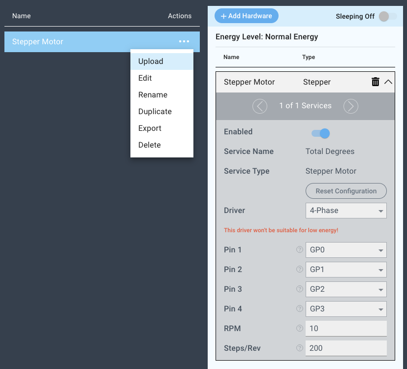
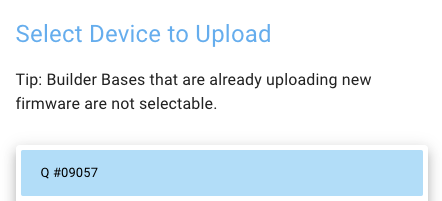
You may now save your firmware file and upload it to one of your clients.
Supported Hardware
Uni-polar Stepper Motor
Downloads
Apps
Firmware
Assets